| John Broskie's Guide to Tube Circuit Analysis & Design |
17 February 2021 Post Number 529
Subwoofer Ideas
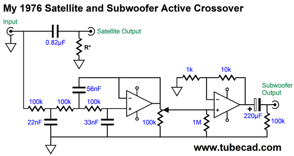
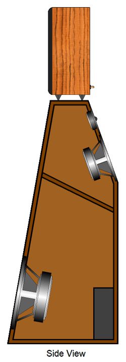
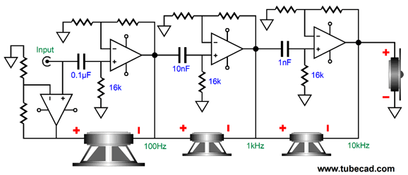
We owned a table saw and radial-arm saw, so cutting up sheets of both plywood and press-board was easy. Most of the subwoofer cabinets were either acoustic-suspension or transmission-line types, as I disdained bass reflex, finding the low bass far too thumpy, bumpy, lumpy. At that time, I was lucky enough to acquire a single Klipsch Korner Horn without its horn midrange and tweeter. It didn't go as deep as my other subwoofers, but it did go much louder. All of which helps to explain why I had to design and build an active crossover for the satellite speakers and subwoofer. OpAmps were becoming readily available; and what had once seemed an impossibly complicated circuit, now could be made with a few LM741 or LM301 OpAmps and a handful of resistors and capacitors. While in college, I built my monster subwoofer, which required at least three strong men to lift. It was a no compromise two-woofer, dual transmission-line cabinet with 2.5-inch walls. (I had discovered a source for super-dense press-board [MDF] 1.25-inch workbench tabletops.) Since this was a no compromise subwoofer, it had to be paired with a no compromise active crossover. The previous active high-pass filters I had built worked well to limit the low frequencies, but added an unacceptable veil to the rest of the satellite speaker's sound. (High-quality OpAmps were still a few decades away.) My workaround was to use a passive 1st-order 100Hz high-pass filter for the satellite speakers and an active 3rd-order 100Hz low-pass filter for the subwoofer's amplifier.
In high school, I had on my own discovered that capacitors sounded different, which at the time was a crazy notion, as no one else was making the claim. I was convinced the sonic differences must be due to poor capacitor tolerances, so I used a capacitance meter to match capacitance values; nonetheless, the sonic differences persisted. Growing up in Silicon Valley gave me access to a dozen electronic surplus stores and another dozen retail electronic part stores. I gathered up as many different capacitor types and brands but of the same value as I could and held sonic shootouts. One conclusion I reached was that long, thin capacitors sounded better than short, fat capacitors. One capacitor was the clear winner, an aerospace-grade film capacitor in a metal sheath, which I now assume was a Teflon capacitor, although a friend supposed that it might have been a wet-slug tantalum capacitor instead. I returned to the surplus store and bought all that they had. Sadly, it held an awkward value, such as 0.82µF. I let others who owned subwoofers borrow my passive/active crossover and, invariably, they wanted one; bad news. The problem was that I made my own PCBs by hand, laying out adhesive donuts and stripes to bare copper PCB boards, etching, and drilling the boards. In other words, I didn't want to make another, so I insisted on what I deemed an insanely high price, which I was sure would dissuade any potential buyer: $200. My apartment's rent was $180 at the time, so $200 was a near astronomical price. They gladly paid it, alas. For about a year, I was living high, as each tax-free $200 sale upped my standard of living substantially. It ended when I used up my last pair of 0.82µF capacitors. I understand that PS Audio started when Paul and Stan built OpAmp-based phono stages for themselves, then friends, and then the world. If I had 100 of the magic-sounding capacitors, I would have had the PCBs professionally fabricated and JB Audio might have been born.
(About 25 years ago, when I lived in Scotts Valley, California, my neighbor who was a graphics designer received a phone call from a huge and famous company in Silicon Valley, such as HP or AMD. They had heard that he was the best at creating a certain type of animation and they needed one in two days. He explained that he could certainly make what they wanted, but that doing so in just two days was impossible. They countered that given enough money, nothing was impossible, so how much money would it take to make it possible? He pulled a number out of the air and said $8,000—he estimated that it would take him about 8 hours to make the animation, so we would be charging $1,000 per hour. He was told that in less than two hours a courier on a motorcycle would arrive at his door with a check for $8,000 and that the animation had to be ready by 9am Thursday. He went to work. Had he stated $10,000, he would have gotten $10,000.) One friend wanted one of my subwoofer crossovers, even though he didn't own a subwoofer, but he planned on buying two. In post 404, I told the following story.
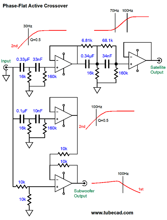
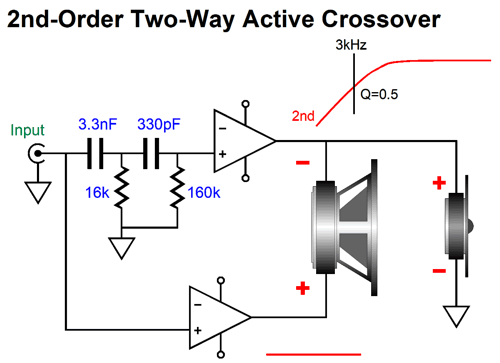
Why did his setup sound so good? Raising the top loudspeaker off the floor no doubt helped the midrange and high frequency clarity, but without sacrificing the lows, as the bottom loudspeaker's woofer remained close to the floor. In addition, the top speaker didn't have to contend with deep bass frequencies, preserving its midrange purity. All of this helped, but it does not go far enough to explain the improved performance. Think about it: his identical Advent loudspeakers all shared the same frequency and phase response, so the active crossover worked beautifully. This is not the usual case. Few subwoofers offer bandwidth that extends beyond 1kHz. In addition, the subwoofer's own intrinsic low-frequency cutoff defines a high-pass filter of either a 2nd-order or 4th-order slopes; so, too, the satellite loudspeaker's own intrinsic low-frequency cutoff defines another high-pass filter. In other words, the results with dissimilar loudspeakers are not likely to match those of my friend's four identical Advent loudspeakers. Here is an example: imagine a small two-way loudspeaker with a 6-inch woofer and dome tweeter. The cabinet is an acoustic-suspension (sealed with no port), with a resonant frequency (Fc) of 70Hz and Q of 0.5, which means critically damped and down -6dB at 70Hz. The subwoofer situated below is also an acoustic-suspension type, with a resonance frequency of 30Hz and Q of 0.5 as well.
If we use a crossover frequency of 100hz between the two loudspeakers, we won't get our desired results, as the two speakers are too dissimilar to blend into a cohesive unity. What to do? Let's start with the active crossover that works beautifully in SPICE simulations, but will falter with real loudspeakers.
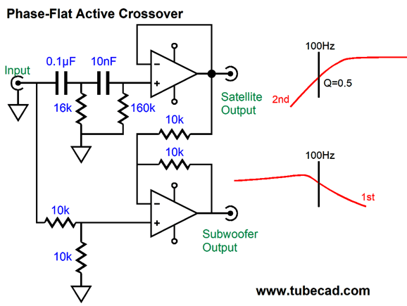
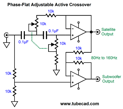
We can even easily make an adjustable phase-flat active crossover.
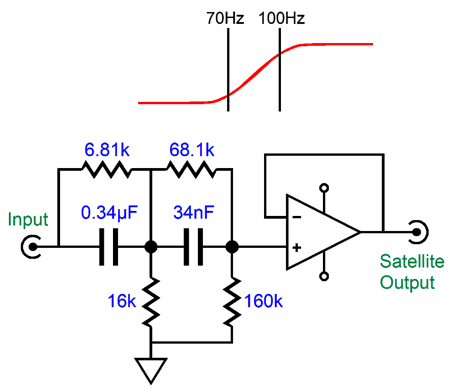
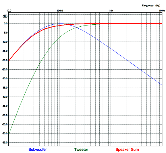
The satellite speaker's power amplifier sees a 2nd-order Linkwitz-Riley high-pass filter; the subwoofer's amplifier, a bumpy 1st-order low-pass filter. The result is a frequency-flat and phase-flat summing. A square wave goes in and a square wave comes out. Wonderful, but the loudspeakers let us down. The first step is to undo the satellite's 70Hz intrinsic 2nd-order high-pass filter. The following shelving network effectively raises the turnover frequency to 100Hz, as if the speaker's Fc was 100Hz.
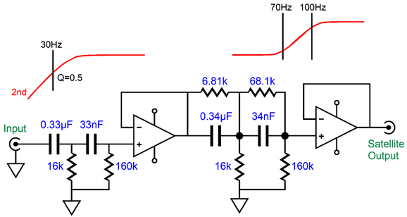
The two cascaded 1st-order shelving networks act as a 100Hz 2nd-order high-pass filter that runs out of steam at 70Hz. In other words, the satellite speaker's output will act as if its resonant frequency was 100Hz, rather than 70Hz. Note that this shelving network does not come close to providing the deep attenuation of low-frequencies that a true 100Hz 2nd-order filter would. The next step is to bring the subwoofer and satellite speaker into alignment with the subwoofer's resonant frequency of 30Hz. We do this by placing a 2nd-order 30Hz high-pass filter in series with the shelving network.
Now, both the subwoofer and satellite speaker see the same 30Hz high-pass filter. Note the satellite speaker now sees both the 30Hz high-pass filter and the shelving network, which unburdens its woofer, as the 30Hz filter's low-Q delivers a shallow turn over. All that is needed now is to create the subwoofer's amplifier's input signal.
The differential amplifier sees the flat input signal and the output from the 100Hz 2nd-order high-pass filter. Its output presents the same small bump at 100Hz and the same 1st-order low-pass filter.
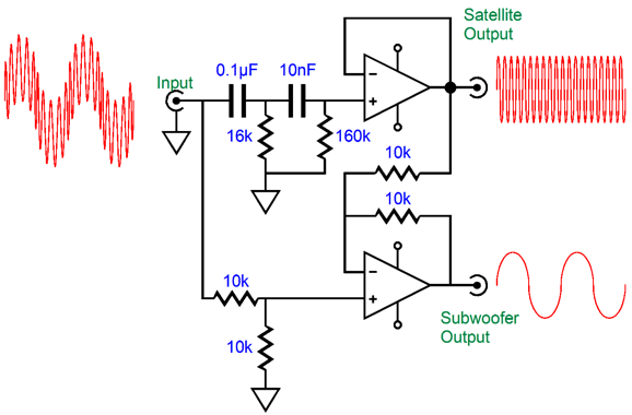
Will this arrangement pass a square wave? It can, if the frequency is enough higher than 30Hz, say, 3kHz. Effectively what we have done is impose a phase-flat 100Hz crossover and a not-phase-flat 2nd-order high-pass filter at 30Hz on the satellite speakers. The math behind the shelving network is easy enough. First we specify the two transition frequencies of the satellite speaker's resonant frequency, Fc, and the desired crossover frequency between subwoofer and satellite, Fcrv. We must cascade to shelving networks, with the second holding resistor values ten times larger and capacitor value ten time smaller. We specify a value for resistor R1. Then we use the following formula to find the capacitor's value. C = 159155/R1/Fc where the result is in µF. Next, we find resistor R2's value with this formula. R2 = R1Fc/(Fcrv – Fc) Of course, we could turn things around and start by specifying the capacitor value and finding resistor R1's value. R1 = 159155/C/Fc For example, let's say we had 0.1µF capacitor that we wished to use. Using the same 70Hz and 100Hz transition frequencies yields a value of 22,736 ohms for R1. Thus, R2 would equal 53,051 ohms. The second shelving network would then hold a 0.01µF capacitor and a 227,360 and 530,510 ohm resistors. (The closest 1% resistor value is good enough.)
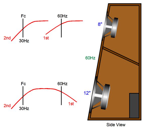
Single Subwoofers with Two Amplifiers The crossover could be a simple 1st-order type. This may seem inadequate, but the smaller woofer would still be down 6dB at 30Hz. The wavelength at 60Hz is about 19 feet, so the relatively close spacing of the two drivers would easily blend together their outputs. If a passive subwoofer were built along the two-way design, the inductor and capacitor would be huge in value. For example, to cross over passively a 4-ohm woofer at 60Hz requires a 663µF capacitor. In contrast, with an active crossover, we would use a 0.1µF capacitor. Since the larger woofer is closer to the floor, its SPL will be boosted, so its signal level would have to be reduced to bring it in line with the smaller woofer.
Another possible use for two power amplifiers is to build a subwoofer qua (i.e. serving as) speaker stand, with a back-firing internal fullrange speaker system, albeit a small speaker system. One power amplifier would drive the large subwoofer driver, while the second amplifier would drive the back-firing speaker. Ideally, we could control the amount of rear radiation power with a remote control, as no doubt some music benefits from plenty of reflected sound reinforcement, while other music doesn't. By the way, the back-firing speaker system would see the same active crossover frequency that the satellite loudspeaker atop does.
Decades ago, I experimented with back-firing additional loudspeakers and rear ambiance loudspeakers. What I found was that, at first, they didn't seem to add much. But with an extended listening period, shutting down the added speakers left the original two-speaker sounding rather pathetic and wimpy. I also noted that I didn't need to crank up the sound to get the desired sense of big sound, something my neighbors surely appreciated. My rule was to increase the indirect sound level until it was obvious, and then I backed off a bit. This is similar to my approach to setting up subwoofer volume: increase the subwoofer output until the system sounds balanced, and then reduce the subwoofer's volume, as invariably it was too high. If it sounds like there's a subwoofer, the subwoofer is playing too loudly.
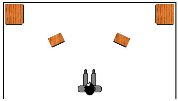
Subwoofers in the Corners
Okay, let's say we accept the premise. Nonetheless, we still face the problem that the sound leaving the satellite speakers will hit our ears before the subwoofer's sound. What to do? What we need is a way to time delay the signal for the satellite speakers. With an open-reel tape playback, we could possibly add a second pickup head behind the primary head, so the satellite speakers would get its time delay. With digital playback, the easy solution is to digitally impose the time delay. This means that the ideal setup would contain the active crossover and DAC in one unit.
Differential Amplifiers and Crossovers
The amazing result is that all four outputs sum to unity and phase flat. Well, this arrangement got me thinking about tube-based differential amplifiers and possible alternatives. One such possibility is to use 1:1 signal transformers in place of the differential amplifiers, as a transformer is an intrinsically differential device.
If the same signal appears at both ends of the transformer's primary, that signal does not appear at the secondary. Another intrinsically differential device is a loudspeaker driver. If we attach both speaker terminals to 40Vdc or 40Vac, nothing happens. Since there was no voltage difference across the voice coil, there is no sound, no diaphragm movement, no smoke. Well, what if we replace a differential amplifier with a speaker driver?
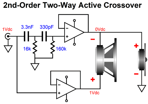
What we see here is an active two-way crossover and bi-amp amplifiers combined. The top amplifier's input signal passes through a 2nd-order 3kHz high-pass filter, while the bottom amplifier's input signal is full bandwidth. Yet the woofer effectively sees a phase-flat crossover at 3kHz, with a trailing 1st-order slope. Let's use 1Vdc as an input signal.
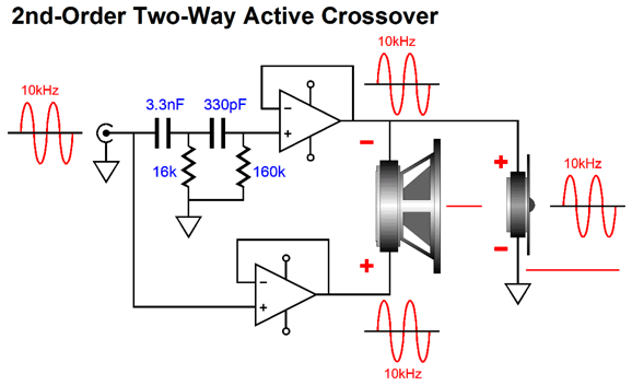
The top amplifier cannot pass the DC signal, as the two capacitors block DC voltages. The bottom amplifier (actually a power buffer in the schematic) does pass the 1Vdc to its output. The woofer's diaphragm pushes out, but the tweeter is blind to the DC voltage, as its voice coil sees 0V at both ends. Now, let's inject a 10KHz input signal.
The top amplifier readily passes the AC signal, as does the bottom amplifier! Yet, the woofer does not respond, as it sees no differential signal. No voltage difference between speaker terminals, no sound. With an input signal of 3kHz, both woofer and tweeter will deliver output. Although this setup definitely saves on parts, is this a good idea? It is, if saving parts is our goal. One disadvantage to this setup compared the usual bi-amp setup—wherein a complementary low-pass and high-pass active crossover is used to feed two power amplifiers and each speaker driver terminates into ground—is that we do not get the potential higher sound level that the traditional bi-amp setup offers. For example, if the input signal consists of two tones, one at 100Hz and the other at 10kHz, the traditional bi-amp setup can deliver the maximum output voltage swing from each amplifier.
In contrast, this simpler arrangement limits the bottom power amplifier to effectively only half of the 100Hz output voltage swing, as the bottom amplifier must also deliver the 10kHz signal along with the 100Hz signal, with the two frequencies creating a peak equal to twice that of a single tone. In other words, the bottom amplifier is extra burdened. Its input signal holds two AC tones that add and subtract, and the peak addition causes a peak-output-voltage swing twice as large as a single tone. Assuming a maximum output voltage swing of 10Vpk from each amplifier, since the top amplifier does not have to produce the 100Hz tone, it can pass the 10Vpk 10kHz signal; the bottom amplifier must produce both tones and, thus, cannot pass a 20Vpk output signal, only a 10Vpk signal. Moreover, if one amplifier clips, the woofer will always experience it. Depending on the application, however, this loss of potential output may not outweigh the savings in parts; for example, a tabletop radio or two-way Bluetooth headphones. (If only I were a patent attorney.) In addition, this part-saving design requires that both drivers offer the same SPL, otherwise a padding network will be needed on the more efficient tweeter.
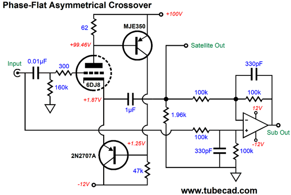
Shown above, this is the four-way implementation of the speaker as differential device arrangement. One thought that just crossed my mind was that this setup might make a lot more sense with a monopolar power supply. Imagine a powered loudspeaker that used an external 48Vdc switcher power supply. Normally, all the drivers would need to see a large-valued coupling capacitor, but not in this arrangement, as only the tweeter needs one to couple it to ground. In other words, the woofer, midrange-woofer, and midrange would all see the same 24Vdc at their terminals, so no coupling capacitors would be needed. John, all this is great, but where are the tubes? Well, here is a hybrid phase-flat crossover, with a crossover frequency of 100Hz.
The White cathode follower is the heart of the high-pass filter. It might look like a 1st-order filter, but the output coupling capacitor forms the second half of the 2nd-order high-pass output. An OpAmp handles the subwoofer output. The differential amplifier produces the needed low-pass output for the subwoofer—with an added 4,800 Hz low-pass filter via the two 330pF capacitors. Why? OpAmps are more stable if their bandwidth is limited and the tube portion of the circuit will produce high-frequency phase shifts that could trip up full-bandwidth operation of the OpAmp. We can take advantage of the -12Vdc power-supply rail, which will allow us to use one fewer triode.
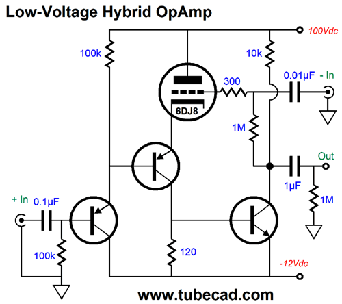
This is a Triadtron topology, which forces the 6DJ8 triode to draw a near constant current flow. Okay, now things become more interesting. Since we only used one 6DJ8 triode, so what should we do with the second triode? How about a tube-based differential amplifier—or at least a hybrid differential amplifier?
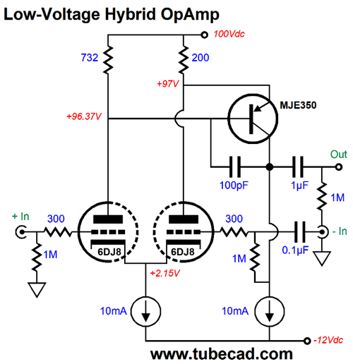
Or, we could be more generous and use two 6DJ8 triodes.
This differential amplifier runs off an equally low B+ voltage. Missing is a safety diode that bridges ground to the two tethered cathodes. We could get extra fancy by adding a cathode follower or an emitter follower, but as it stands the performance is excellent.
Music Recommendation: Dreamers
I plan on checking out her other albums at Amazon Music, two of which are in a high-res format, as I find her smoky voice quite compelling. //JRB
User Guides for GlassWare Software
For those of you who still have old computers running Windows XP (32-bit) or any other Windows 32-bit OS, I have setup the download availability of my old old standards: Tube CAD, SE Amp CAD, and Audio Gadgets. The downloads are at the GlassWare-Yahoo store and the price is only $9.95 for each program. http://glass-ware.stores.yahoo.net/adsoffromgla.html So many have asked that I had to do it. WARNING: THESE THREE PROGRAMS WILL NOT RUN UNDER VISTA 64-Bit or WINDOWS 7, 8, and 10 if the OS is not 32-bit or if it is a 64-bit OS. I do plan on remaking all of these programs into 64-bit versions, but it will be a huge ordeal, as programming requires vast chunks of noise-free time, something very rare with children running about. Ideally, I would love to come out with versions that run on iPads and Android-OS tablets.
|
I know that some readers wish to avoid Patreon, so here is a PayPal button instead. Thanks. John Broskie
John Gives
Special Thanks to the Special 87 To all my patrons, all 87 of them, thank you all again. I want to especially thank
I am truly stunned and appreciative of their support. In addition I want to thank the following patrons:
All of your support makes a big difference. I would love to arrive at the point where creating my posts was my top priority of the day, not something that I have to steal time from other obligations to do. The more support I get, the higher up these posts move up in deserving attention.
If you have been reading my posts, you know that my lifetime goal is reaching post number one thousand. I have 471 more to go. My second goal was to gather 1,000 patrons. Well, that no longer seems possible to me, so I will shoot for a mighty 100 instead. Thus, I have 13 patrons to go. Help me get there.
Support the Tube CAD Journal & get an extremely powerful push-pull tube-amplifier simulator for TCJ Push-Pull Calculator
TCJ PPC Version 2 Improvements Rebuilt simulation engine *User definable
Download or CD ROM For more information, please visit our Web site : To purchase, please visit our Yahoo Store: |
|||


| www.tubecad.com Copyright © 1999-2021 GlassWare All Rights Reserved |