| John Broskie's Guide to Tube Circuit Analysis & Design |
|
14 August 2020 Post 510
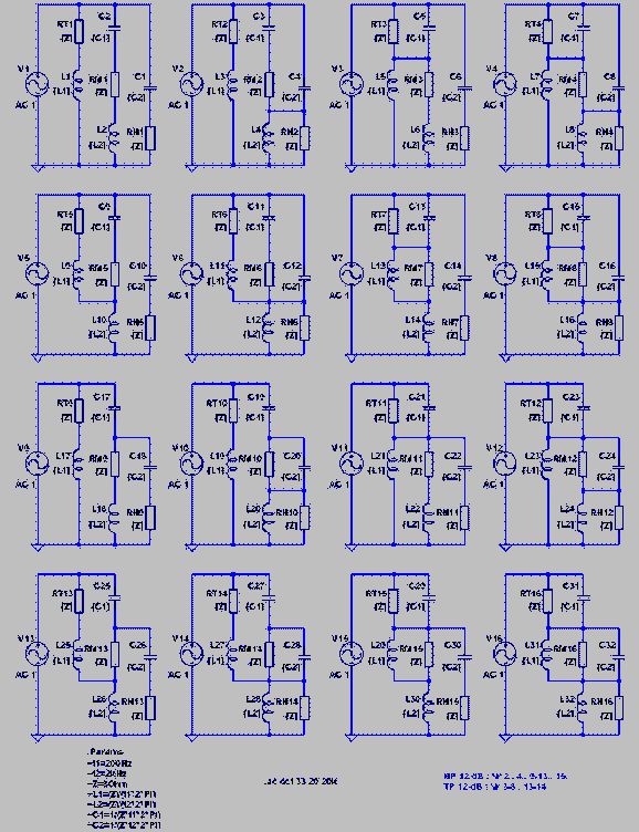
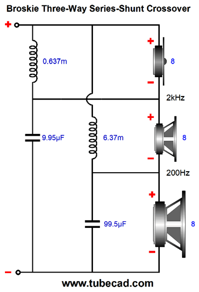
Prior Crossover Art
Don't see it? Look in the upper right corner, then flip the circuit, which would then look like the following.
By the way, I like Thomas's style, as it reminds me of my own. Basically, you start with a seed circuit, in this example a woofer and midrange and tweeter, then build upon it and then spawn a variation, then another variation, until you exhaust either all the possibilities or yourself.
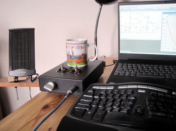
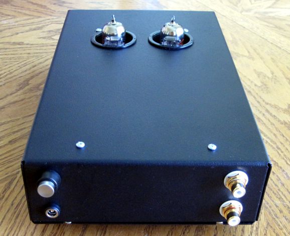
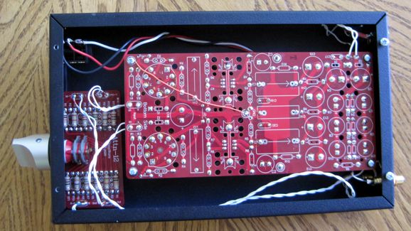
SRPP Coffee-Cup Warmer My goal was to keep the incoming 12V AC voltage tucked into a corner, with the power switch located in the corner, not on the front. Why? I have run into 60Hz hum issues with small enclosures and front-panel power switches that switch AC (DC is not a problem). My second goal was to keep the input signal wires far away from the 12Vac.
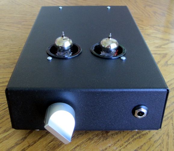
On the right, we see the two input RCA jacks; on the left, the push-button power switch on top and the AC power jack below it. It's essential that the power jack be fully isolated from the chassis. Below, we see the headphone amplifier's insides.
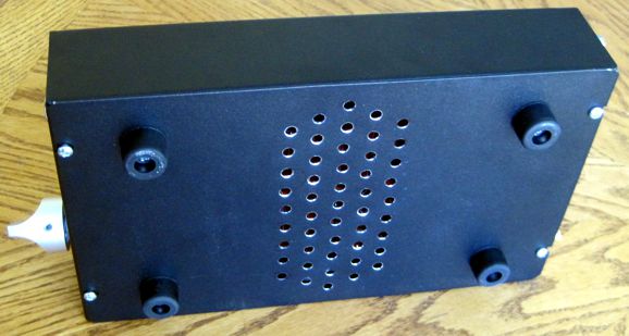
Note how the 12Vac is restricted to the top-right corner, while the incoming audio signal hugs the bottom of the chassis. Also note where the heatsinks reside on the PCB, then note where are the ventilation holes I drilled into the bottom panel.
Since the bottom panel, like the enclosure above it, is made of steel, I need to paint the exposed metal soon. (Clear nail polish works well.) The enclosure does get hot, but not too hot to touch. In other words, it's not much of a coffee-cup warmer.
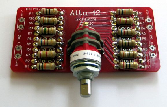
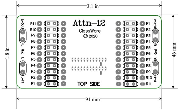
The volume control is not a potentiometer; instead, it is a stereo 12-position stepped attenuator that holds a two-deck Grayhill rotary switch with hard-gold switch contacts.
Attn-12 Stepped Attenuator
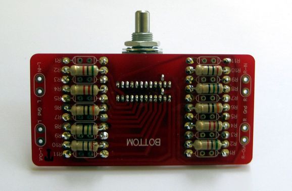
I used 1W carbon-film resistors which proved a tad too tight to place all of them on the topside of the PCB, so I soldered half of them on the bottom.
You might imagine that 12 decrements in sound level is far to coarse, but I find that it works well with the headphone amplifier, as all the sound sources I use contain their own digital volume controls. In fact, I have used—for exactly ten years now—my old version of this attenuator that held an 11-posistion, 2-pole Elma hard-gold-contact rotary switch in my octal Aikido headphone amplifier.
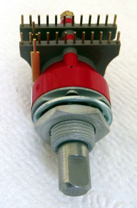
Unfortunately, the Swiss Elma switches cost a fortune and the company requires that you buy thousands of dollars worth of them at a time. See my blog post 181 for more details on the old attenuator. I was lucky enough to source the American Grayhill 12-position stereo switches with hard-gold contacts.
If you use a sealed switch with audio signals, it is essential that the contacts are hard gold. True, silver is a better electrical conductor than gold, but it makes a poor switch contact in a sealed switch when dealing with small audio signals. On the other hand, silver makes a better contact material when you are switching higher-voltage, high-current loads—something audio stepped attenuators never do, as the line-level audio signal cannot burn off silver oxide tarnish the way 1A at 120Vac switching can. Many ignore this advice and use silver-contact switches anyway and get great results—for a while, then poor results, and, finally, no results. The silver switch workaround is to employ a knife edged switching scraper that shaves a thin layer of contact material off with each pass. (A switch with knife contacts requires periodic vacuuming, as the shavings can short out portions of the switch or circuit. In other words, these switches are open structures, not sealed.) On the other hand, if the switch offers an open structure that lets you readily see the contacts, then silver or any other contact metal can be used, as you can apply contact cleaner when needed, which is impossible with a sealed switch. One quick way to tell if a sealed switch really is suitable for audio signals is its maximum current rating. If it's only 30mA, then it is good to go; if it's over 500mA, begin to worry.
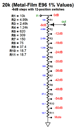
The closest analogy to the series attenuator is a normal audio-taper potentiometer used as a volume control in 99.99% of audio gear. It consists of a rotary switch that holds many differently-valued resistors placed in series, creating a long chain of resistors, with each resistor connection attached to a switch contact. The rotary switch’s moving contact then selects between resistor connections, thus providing a selectable amount of fixed signal attenuation. The chain of many fixed resistors wired in series defines the total input resistance of the attenuator.
Thus, we have swapped a little conductive paint for a lot of lead-tin. In addition, if one of the resistors is sonically poor sounding it will always make itself heard as all the resistors see all of the signal current, since they are all in series. In other words, the series attenuator works best when it doesn't’t hold too many steps. How many is too many? As with all things analog, there is no specific answer, yet we can absolutely know that each additional step will add some miniscule sonic degradation to the signal. So why bother with a stepped attenuator? The answer is simple: even the most expensive potentiometers sound much, much worse. The Atten-12 is available now at the GlassWare-Yahoo store.
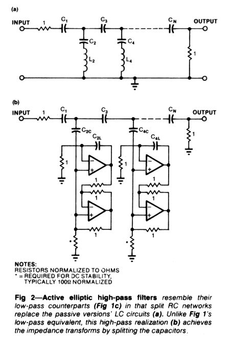
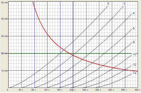
Tube-Based Equalizer For example, I once built a fuzz box for a friend that held a 12AX7 and 12AU7 tubes and ran an insanely low B+ voltage, say 48Vdc. The 12AX7s were configured in a grounded-cathode amplifier topology with FET constant-current source loading. The two grounded-cathode amplifiers cascaded, so the resulting gain was insanely high, which then cascaded into two parallel 12AU7 triodes in a cathode follower configuration, also constant-current source loaded at their tied cathodes. He loved the effect box, as it created an extremely enhanced sustain, as it acted as a soft compressor, which clipped the high amplitude portion of the output signal, but let the low-level signal pass through, so the dying signal became a far greater portion of the output signal. I gave him many back-up tubes, which were high-quality tubes that were military pulls. He told me that they all sounded radically different from each other. This troubled me, as they were all high-end brands, such as Mullard and Amperex, and I had tested all the tubes first, with all proving to be first-rate performers. I had him return the tubes to me, so I could test them again in my phono preamp. They all sounded the pretty much the same, excellent, with only the most trivial sonic straying perceivable. (By the way, he had labeled the tube cartons with the name of the bluesman he thought the tube had summoned his distinct guitar sound, such as Buddy Guy and Hubert Sumlin.) I brought the tubes back to his place and he played his guitar for me. I definitely heard what he was talking about, as each 12AX7 had a different sound. Okay, why the discrepancy? My best guess was that in my phono stage, whose B+ voltage was 430Vdc and the 12AX7 plate voltage was 250Vdc and its idle current was a relatively hot 2mA. In contrast, the effect box ran a 42Vdc B+ voltage and experienced a trivial idle current flow. Now, if we examine the 12AX7's plate curves, we see that at 250V and 2mA, the 12AX7 is quite linear, whereas at the bottom-left of the curves we see a gooey mess, which allowed each 12AX7 to depart from linearity in its own special way. Yes, this does echo the beginning sentence of Tolstoy's novel, Anna Karenina: "All happy families are alike; each unhappy family is unhappy in its own way." All linear 12AX7s are alike; each non-linear 12AX7 distorts in its own way. I mentioned this experience to a friend and he told me of his similar experience designing effects boxes, as musicians wanted nearly infinite distortion. His workaround was to use saturating inductive devices, such as inductors and transformers. This brings us back to equalizer circuits. Most old tube-based equalizers held a handful of inductors, which are both a huge pain to source and are hum magnets, if not arranged carefully or shielded. Well, is it possible to make an equalizer without inductors? Yes, usually gyrator circuits bases on OpAmps are used to mimic the inductors.
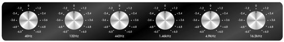
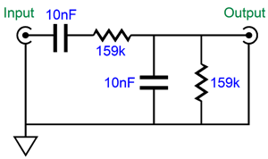
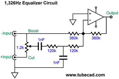
Another workaround is to rely solely on resistors and capacitors, which results in a softer, gentler equalization. About three decades ago, I did the fancy math and concluded that each equalizing band of frequencies' center frequency should be 0.3 of the next band's center frequency: for example 30, 100Hz, 333Hz, 1110Hz, 3700Hz…. Unfortunately, the reasoning is lost to me now. My guess is that this ratio resulted in the flattest phase response. Here is the core equalization network:
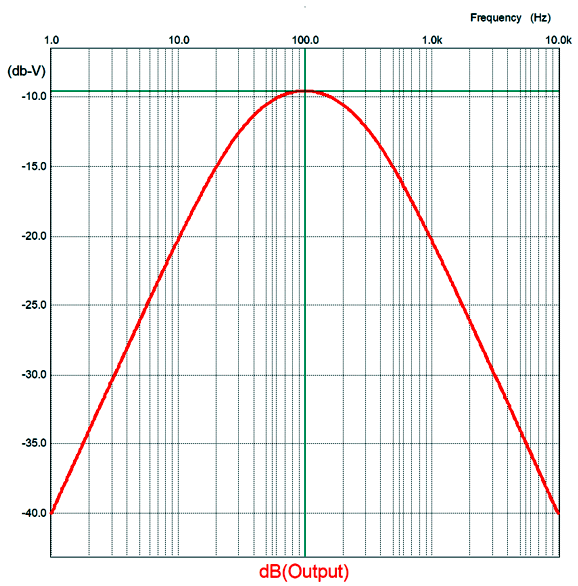
The two capacitors share the same value, as do the two resistors. We find the center frequency with this simple formula: Frequency = 159155/C/R where C is in µF. If we inject 1Vpk into the circuit's input, we get 0.33Vpk at the output.
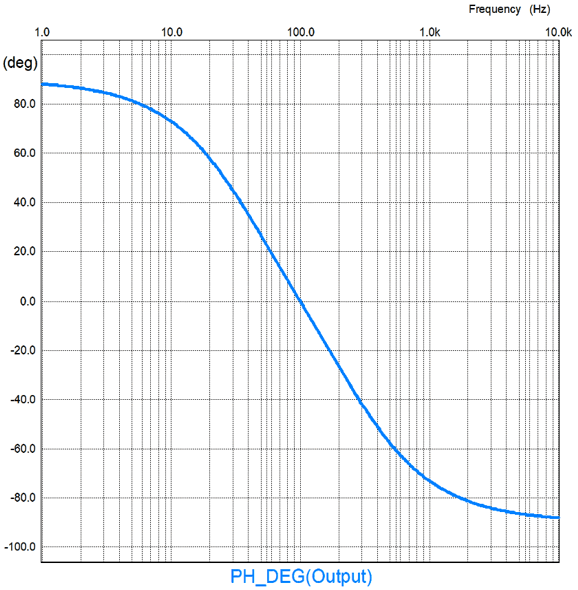
The center frequency is 1kHz and the output is -9.54dB down (i.e. 1/3 the input voltage). The Phase shift is gentle.
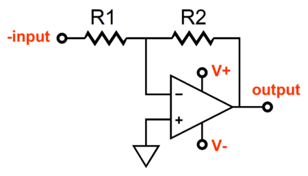
Note that the phase shift is zero at 1kHz; +45 at 300Hz and -45 at 3.3kHz. Much like the tube-based mixer circuits, the tube-based equalizer uses the inverting amplifier configuration.
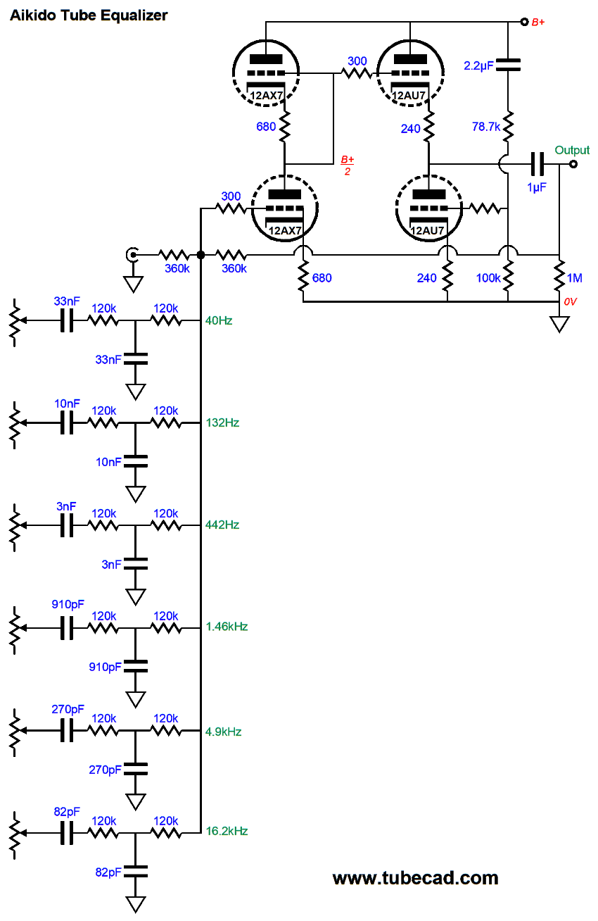
I actually planned on covering an equalizer circuit back in post 507, wherein I observed, "that most standalone DACs offer a set of balanced outputs, which are seldom used. I also note that many DACs offer digital volume controls and that many DACs put out a truly hot output signal. My mind puts these three observations together and wonders how all three could be utilized, i.e. exploited." Well, my equalizer circuit requires a balanced set of input signals; in addition, it needs to see a gain of 3 for the output of the equalization network, whose output is 1/3 of the input signal. Thus, we multiply 120k by 3 and get 360k.
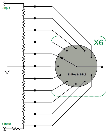
XLR jacks are usually intended to drive 600-ohm loads, so I placed a 1200-ohm potentiometer across both balanced outputs. With the potentiometer centered, no audio signal is had, so no equalization obtains and the input signal emerges at unity-gain and flat in frequency response. (Note that the inverted input signal gets inverted, so no net phase shift results.) Rotate the potentiometer and we get either a boost or a cut at the center frequency of 1326Hz. Somewhat paradoxically, when the equalization network sees a positive input signal, the result is dip at the network's center frequency. Now, let's replace the potentiometer with 11 resistors, whose combined resistance equals 1200 ohms. We then send the 11 connections out to as many an 11-position rotary switches as we need, say six.
In other words, we do not need 6 potentiometers or six 11-position stepped attenuators, only 6 rotary switches and no extra resistors.
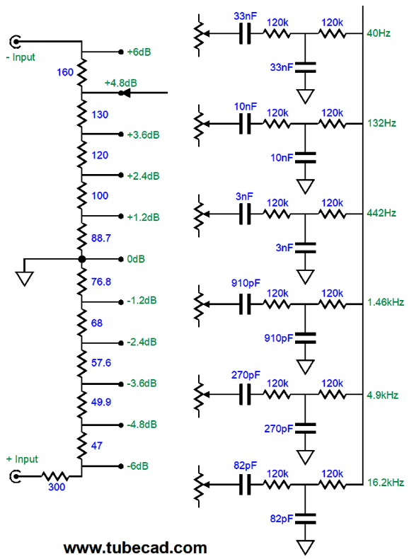
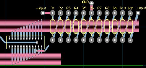
Each band gets its own 11-position rotary switch. If a stereo equalizer were built, then the switches would need to be 11-position, two pole types. What follows is a quick and dirty design example of a PCB layout.
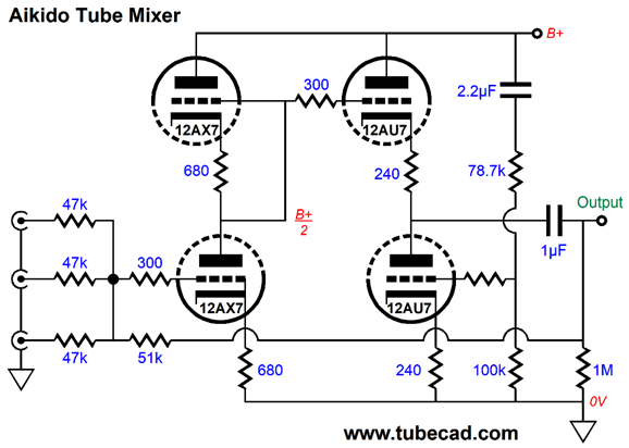
Only one 11-position switch is shown, but five more would run down the track formed by the 22 long horizontal traces, with each channel getting 11 signal traces. Of course, we could point-o-point wire the six switches, which wouldn't prove two difficult with ribbon cable. The next step is to replace the OpAMp with a tube-based inverting amplifier. Let's use the one shown in my last post for a tube-based audio mixer.
Of course, only one input is needed and stereo would require two of these circuits.
Let's call this part-one of a two part post on a tube-based equalizer.
Lowering Line-Stage Gain
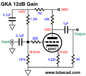
The formula for the gain of a grounded-cathode amplifier, with an unbypassed cathode resistor, is the following: Gain = mu ∙Ra/(Ra + rp +[mu + 1]Rk) If we solve for the cathode resistor (Rk), we can specify the desired gain. In other words, with the right valued cathode resistor, we can hit our target gain. Rk = (Ra[mu/Gain – 1] – rp) / (mu + 1) Let's use a 6SN7 with a plate resistor equal to 24k and with a target gain of 4 (12dB). The B+ voltage is 240Vdc and the desired idle current flow is 5mA, which implies a plate voltage around 120Vdc, as we will ignore the voltage drop across the cathode resistor right now. After inspecting the 6SN7's plate curves, we see that its mu is equal 21 and its rp equals 9200 ohms at the intersection of 120V with 5mA.
Next, we plug these numbers into the previous formula. Rk = (24000[21/4 - 1] – 9200)/(21 + 1) = 4218 We then check our result by plugging the values into the grounded-cathode amplifier gain formula: Gain = 21 ∙24000/(24000 + 9200 + [21 + 1]4218) = 4 Now we face the problem that a 4218-ohm cathode resistor with a 24k plate resistor and a B+ voltage of 240Vdc does not result in an idle current of 5mA; instead, we get a plate voltage of 196V and an idle current of 1.8mA. The workaround is to add fixed grid bias to the mix. In other words, we must make the 6SN7's grid more positive to get its plate current flow up to 5mA. Okay, great, but by how much? Starting with what we know for certain, such as the plate voltage will 120Vdc, as 5mA against 24k equals 120V of voltage drop across the plate resistor and the same 5mA against 4218 ohms equals about 21V, so the 6SN7's cathode-to-plate voltage will be equal to 120V – 21V or 99V. If we inspect the 6SN7's plate curves we see that at intersection of 99V and 5mA the grid voltage is about -2.1Vdc. Thus, the needed grid-bias voltage needs to equal the voltage drop across the cathode resistor (21V) minus 2.1V or 18.9Vdc.
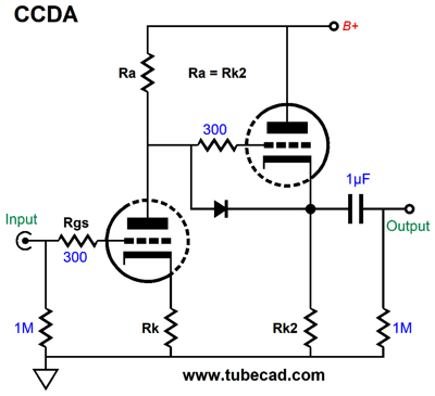
We can go for the constant-current-draw amplifier topology instead.
In fact, we can put in place a DC negative feedback loop.
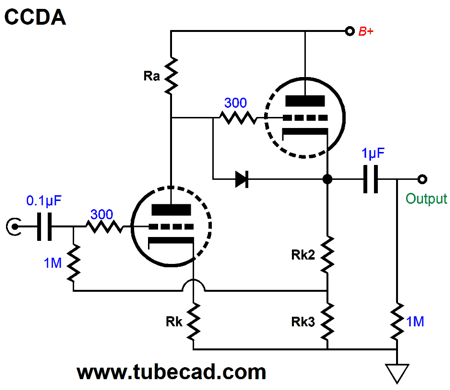
The input grounded-cathode amplifier DC couples to the cathode follower and the cathode follower DC couples back to the input triode's grid. The DC negative feedback keeps the two triodes in tight idle-current alignment. Note that we can add a selectable-gain feature to this circuit.
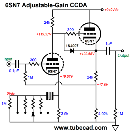
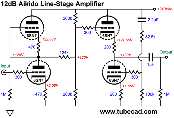
What we have here is a CCDA line-stage amplifier with selectable gain through a five-position rotary switch. Of course, more or fewer positions could be used just as easily. The 1M resistor is needed to be the non-polarized electrolytic capacitor constantly charged up, which will prevent output jumps as we rotate the gain-selector knob. Imagine each increment being 3dB in increased gain. Over the years, I have received emails complaining of too much gain from their Aikido line-stage amplifiers. Here is the workaround.
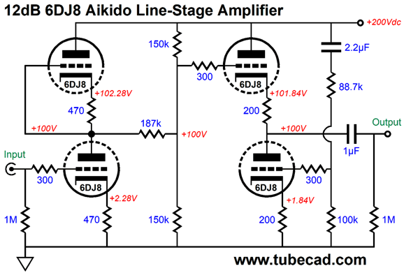
The two 200k resistors are effectively in parallel and equal 100k of resistance, which then forms a two-resistor voltage divider with the 124k resistor. The result is a gain 4 (+12dB) with 6SN7s. If we use a 6DJ8 instead, we will need to impose greater attenuation.
Note the blower B+ voltage, 200Vdc, and that the 200k resistors have been replaced by 150k resistors, while the 124k resistor is replaced by 187k.
Music Recommendation: Across The Universe
His exploration and expansion of the famous and not so famous songs is amazing, which I am sure that Paul and Ringo would agree.
//JRB
User Guides for GlassWare Software
For those of you who still have old computers running Windows XP (32-bit) or any other Windows 32-bit OS, I have setup the download availability of my old old standards: Tube CAD, SE Amp CAD, and Audio Gadgets. The downloads are at the GlassWare-Yahoo store and the price is only $9.95 for each program. http://glass-ware.stores.yahoo.net/adsoffromgla.html So many have asked that I had to do it. WARNING: THESE THREE PROGRAMS WILL NOT RUN UNDER VISTA 64-Bit or WINDOWS 7 & 8 or any other 64-bit OS. I do plan on remaking all of these programs into 64-bit versions, but it will be a huge ordeal, as programming requires vast chunks of noise-free time, something very rare with children running about. Ideally, I would love to come out with versions that run on iPads and Android-OS tablets.
//JRB
|
|
I know that some readers wish to avoid Patreon, so here is a PayPal button instead. Thanks. John Broskie
John Gives
Special Thanks to the Special 85
I am truly stunned and appreciative of their support. In addition I want to thank the following patrons:
All of your support makes a big difference. I would love to arrive at the point where creating my posts was my top priority of the day, not something that I have to steal time from other obligations to do. The more support I get, the higher up these posts move up in deserving attention. If you have been reading my posts, you know that my lifetime goal is reaching post number one thousand. I have 490 more to go. My second goal was to gather 1,000 patrons. Well, that no longer seems possible to me, so I will shoot for a mighty 100 instead. Thus, I have 15 patrons to go. Help me get there.
Only $12.95 TCJ My-Stock DB
Version 2 Improvements *User definable Download for www.glass-ware.com |
||


| www.tubecad.com Copyright © 1999-2020 GlassWare All Rights Reserved |