| John Broskie's Guide to Tube Circuit Analysis & Design |
|
06 November 2016
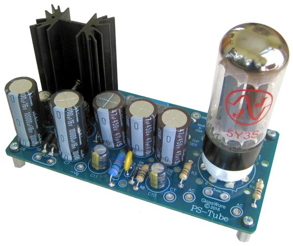
New Power Supply Kit: PS-Tube
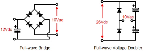
If you are like me, you own a good-sized stockpile of old tube-amplifier power transformers. You know the kind: the type that hold a center-tapped high-voltage secondary, a 6.3Vac heater winding and a 5Vac secondary for the tube rectifier. Such a transformer is perfect for a tube power amplifier. For tube-based line-stage amplifiers and tube phono stages, however, such a transformer is a poor fit. Why? The 6.3Vac heater winding cannot readily be used to power a regulated heater power supply, as 6.3Vac rectifies up to about 7.5Vdc, which does not allow any voltage headroom for a solid-state regulator, even an LDO type. The PS-Tube circuit overcomes this problem by using a voltage-doubler-rectifier circuit, which develops about 16Vdc from 6.3Vac. Here is a comparison between the full-wave bridge and full-wave voltage doubler rectifier circuits.
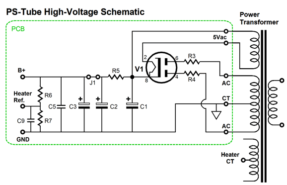
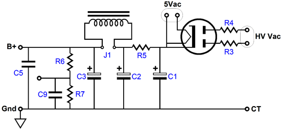
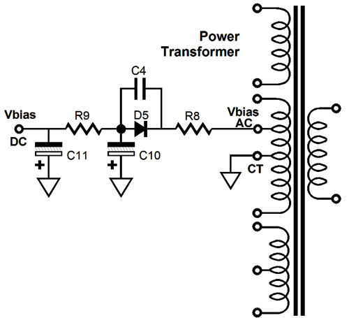
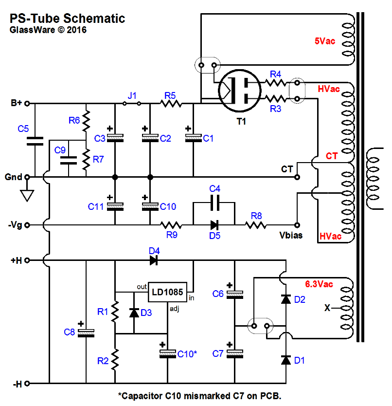
With the 16Vdc we can easily use an LDO voltage regulator to get a clean 12Vdc or 12.6Vdc to the heaters. (I strongly prefer the slightly cooler 12Vdc over 12.6Vdc, as it extends tube life and can result in slightly less distortion.) Of course, all electronic magic comes at a price, as we can never cheat the universe. In the above examples, assuming identical 10Vac transformers, the voltage-doubler circuit on the right will only put out half of the maximum current as the full-wave bridge circuit on the left. Wait a minute John, since we get a little bit more than double the DC voltage from the circuit on the right, we have cheated the universe. No, actually we have just better utilized our parts. If rectifiers didn't present voltage drops, the voltage ratio between the circuits would be 1:2. The formula for finding out how much DC current a 6.3Vac heater winding can yield in this circuit is: Imax = Iac/3.6 where Iac is the heater winding's AC current rating. For example, if the 6.3Vac winding is rated to put out 3A, we can get 833mA of regulated 12.6Vdc voltage. The high-voltage portion of the PS-Tube is the classic setup, with one embellishment. Here is the link to the entire schematic.
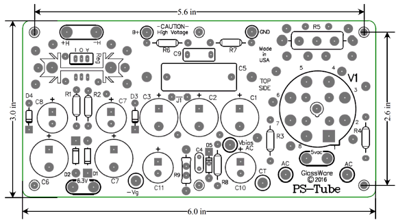
Capacitor C1 is a 47µF 450V capacitor. Why not use a much larger capacitor? In spite of how fashionable big power supply capacitors are these days, they are a bad idea when it comes to tube rectifiers. Why? The tube rectifier cathode cannot take the high current spikes that a large capacitors imposes on the rectifier. Most tube rectifier specifications state a maximum capacitor value of 50µF or 60µF, so the 47µF plays it a bit safe. In addition, capacitors C2 & C3 add a total of 94µF after the R5 RC resistor. Remember that, in a rectifier circuit, the larger the load capacitance, the shorter the charging time and the bigger the current spike. In other words, the average current draw from a power supply might be only 50mA, but the peak current spike through the reservoir capacitor might be 500mA, or much higher. Resistors R3 & R4 are 100-ohm 1W types that limit the inrush current into the tube rectifier. Resistor R5 and C2 form an RC filter. The embellishment is jumper J1, which can be replaced by an external choke (inductor). Capacitor C5 is a 0.68µF 550Vdc bypass capacitor.
Resistors R6 & R7 define a two-resistor voltage divider that allows referencing the heater power supply to some positive voltage. This is an important feature when the circuit holds one triode atop another, as in the Aikido and SRPP circuits. I like to split the difference; for example, if the bottom triode's cathode sits a few volts above ground potential and the top triode's cathode rests a few volts above 100V, I would reference the heater power supply to about 50Vdc. The PS-Tube holds a simple half-wave rectifier circuit for establishing a negative bias voltage. This portion is optional, but it may come in handy.
Many tube-amplifier transformers, however, do not hold a bias-voltage tap on their high-voltage secondary.
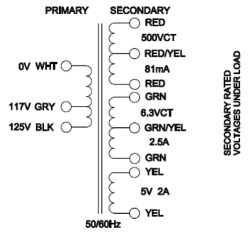
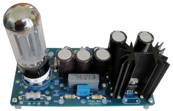
I used a Hammond 270CAX power transformer to test the PS-Tube PCB.
250Vac rectifies up to about 350Vdc, except it doesn't. As I had not loaded the PS-Tube's output with any load, the DC voltage was closer to 415Vdc. With an external load, we can expect the DC voltage to fall to about 320Vdc. Why the huge variance? High-voltage power transformers suffer from poor regulation due to the transformer's high secondary DCR, which in the case of the 270CAX is 232 ohms. In addition, tube rectifiers presents a relatively high plate/anode resistance, which results in a vastly larger voltage drop compared to solid-state rectifiers. Speaking of tube rectifiers, the PS-Tube can be used with the 5AR4, 5R4, 5U4, 5Y3, GZ34, WE 274 rectifiers. The RC filter also drops voltage, so under a heavy load, the 415Vdc can easily fall to 300Vdc. I was surprised by how quickly the B+ voltage developed. Of course, by solid-state standards, it is super sluggish. I was also surprised by how long it took the reservoir capacitors took to discharge. Electrolytic capacitors have steadily improved over the decades.
The new PS-Tube kit is now available at the GlassWare web store. The kit includes all the parts, including many alternate resistor values for the two RC filters, and six aluminum hex standoffs and user guide; an option to include the JJ 5Y3 rectifier is offered as well.
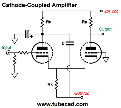
More of the Cathode-Coupled Amplifier
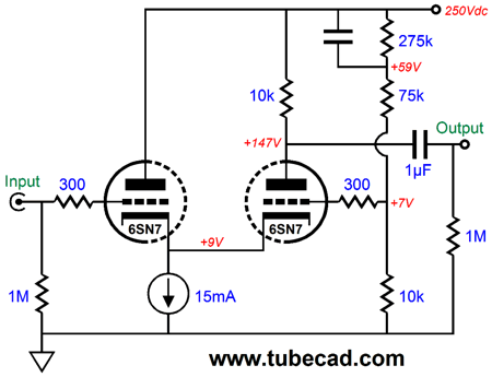
The left triode idles at 5mA, while the right triode idles at 10mA. The left triode sees a cathode-to-plate voltage of 241V, while the right triode sees a cathode-to-plate voltage of 136V. Both cathodes are tied together and sit at +9V. Thus, the left triode sees a cathode-to-grid voltage of -9V, while the right triode sees a cathode-to-grid voltage of -2V. The constant-current source draws 15mA. What happens if the B+ voltage falls to 200Vdc? The left triode will then idle at about 6mA, while the right triode will idle at about 9mA. Interestingly, the distortion goes down, as the two triodes get closer to the same idle current flow. Remember that the cathode-coupled-amplifier circuit offers two features: low input capacitance and lower distortion. The lower input capacitance results from the input triode's plate being fixed, so no Miller-effect capacitance results. The lower distortion results from the two triodes running in current anti-phase, so the output triode tends to unbend what the input triode bent.
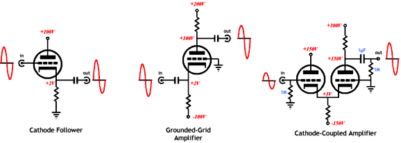
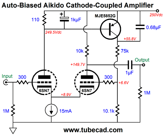
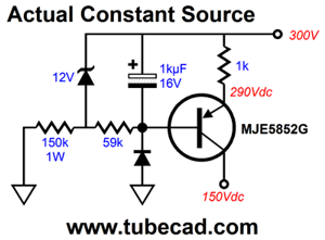
A triode more easily turns on than to turn off; thus, the cathode follower's positive output swing is easier to make than its negative swing. With the grounded-grid amplifier, the opposite is true: the negative output swings are easier to produce than the positive swings. When the two circuits cascade, to a large extent the two opposite bends undo each other. Returning to the circuit, what happens if the B+ voltage rises to 300Vdc? The left triode will see its idle current fall to about 3.5mA, while the right triode's idle will rise to about 11.5mA. Because the disparity between triodes has increased, so has the distortion. One workaround would be the following variation, which uses a PNP transistor to auto bias the grounded-grid triode so that it continues to conduct 10mA, in spite of changes in B+ voltage.
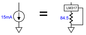
The 75k and the 10.1k resistors define a two-resistor voltage divider, which allows a portion of B+ ripple to appear at the grounded-grid triode's grid. Is that a good thing? Indeed, yes, as this creates a vastly improved PSRR. The way it works is easy enough to understand. As the power-supply noise pulls up in voltage, the grounded-grid triode increases it current conduction, so its output remains fixed at 149.7V; as the ripple drops in voltage, the triode eases up it current flow, so the plate voltage remains at 149.7V, which means that we have achieved a deep power-supply-noise null at the output. The MJE5852G, which is a 400V PNP transistor in a TO-220 package, whose base-to-emitter voltage monitors the current draw through the 54.9-ohm resistor. If triode draws too much current, the transistor conducts more, which increases the output triode's grid voltage, which in turn cause its conduction to increase, thereby forcing a decrease in the input triode's current flow, as both cathodes share the single current path to ground through the constant-current source. Speaking of which, the 15mA flow exceeds the ubiquitous LM334's current limit. The workaround is to use either two LM334s in parallel or to use another device. One possibility is the famous LM317.
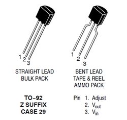
The LM317 makes a surprisingly good constant-current source, as Walt Jung pointed out in audioXpress.
Moreover they are neither large nor expensive, as you can buy two LM317L regulators in the TO-92 package for less than $1.
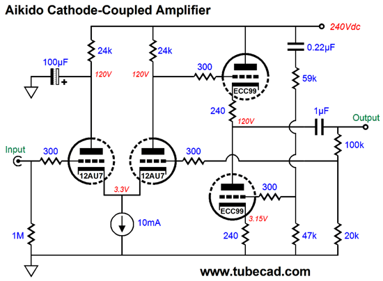
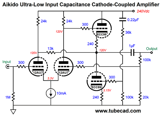
Ultra-Low Input Capacitance Cathode-Coupled Amplifier
Ideally, we want to see no power-supply noise on the plate of the input triode, which is why the large-valued electrolytic capacitor is there. But no matter how large we make this capacitor, some ripple must leak through. There are times when brute force isn't enough. Then it hit me: if we add an extra capacitor that terminated in the negative power-supply rail and whose impedance at 120Hz was the same as the plate resistor (ra) value, the two equal impedances would result in a tie, which would null the power-supply noise on the plate of the input triode. We still need the large-valued electrolytic capacitor, however, to shunt away the audio signal currents. How do we find the right value for this added capacitor? The formula is easy enough: C = 159155 / 120Hz / Ra where C is in µF. Why 120Hz? In countries with 60Hz wall-voltage frequency, the ripple will be greatest at 120Hz. (In countries that use 50Hz, we would use 100Hz.) For example, if Ra equals 15k, then a 0.0884µF capacitor is needed, with 0.091µF being close enough. This trick, of course, will only work with bipolar power supplies. In addition, the positive and negative power-supply rails must hold equal but out of phase ripple. What if no negative power-supply is available, as it isn't in the circuit below? Then we use the Aikido cathode follower to scrub away the power-supply noise.
Well, as I pondered this situation, I realized that I could lose the large-valued electrolytic capacitor by adding one resistor.
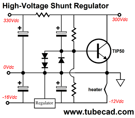
By selecting the right value for the added resistor, we archive an audio-signal null at the input triode's plate, as the output signal is out of phase with the signal the input triode would like to develop at its plate. The more I thought about, I came to the conclusion that I would like to see some audio signal at this plate; in fact, I would like to see the same amount that appears at the input triode's grid and in the same phase. Why? Since the two tied cathodes will partially follow the signal present on the grid, so why not have the plate do the same, which will result in lower input capacitance. The Aikido cathode follower can easily drive the 13k resistor and it provides a fine PSRR and low output impedance. In SPICE simulations, the results were exemplary. Of course, many different tubes could be used, with suitable changes in part values. One combination I would like to try would be a 6SU7 (a 6SL7 with matched triodes) as the cathode-coupled tube and a 6SN7 as the Aikido cathode follower tube. One problem with high-mu triodes, such as the 12AT7, 12AX7, 12AY7, 5751, 6072, is that the cathode voltage will prove too low to use most solid-state constant current sources, such as the LM334. The workaround would be to use a low-voltage negative power-supply rail, say 5Vdc or 6.3Vdc or 12Vdc, which would give the LM334 enough voltage headroom and could be used to power the cathode-coupled triode's heater element. If you are a bit more ambitious, the following high-voltage shunt regulator could be used to make use of the clean -12V provided by a linear regulator.
Reading from left to right, we see the raw DC high voltage enter the circuit. The TIP50 NPN transistor then measures the voltage at its base. If this voltage is too high, the transistor will increase its conduction until the voltage drops to the transistor's nominal base-to-emitter voltage, about 0.6 volts. The three diodes are essential, as they protect the TIP50 from seeing excessive base voltage.
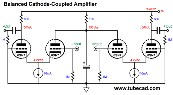
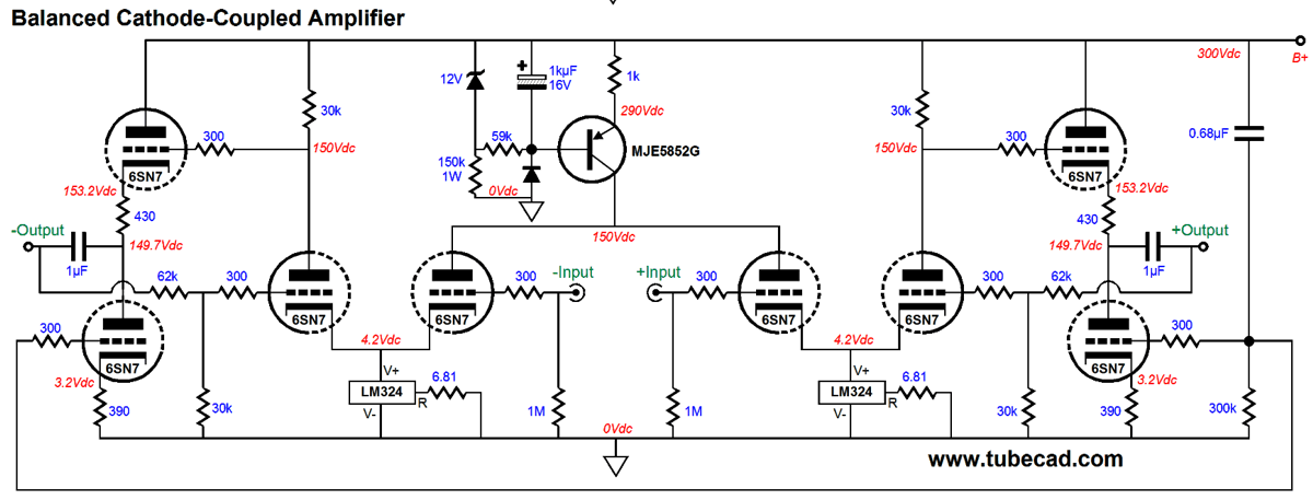
Balanced Cathode-Coupled Amplifier
Everything seems to look good, as the shared 15k plate resistor will see a constant current draw, as the two audio-signal currents flowing through are out of phase with each other. What is wrong is that the circuit offers no CMRR, as an in phase signal presented at both inputs will result in equally large output signal, which will be in phase with each other. Of course, the next balanced piece of equipment, such as a push-pull amplifier may offer a fine CMRR and clean up the mess that it received. But think how much better things would be if it had less of a mess to contend with. The workaround is to add a third constant-current source.
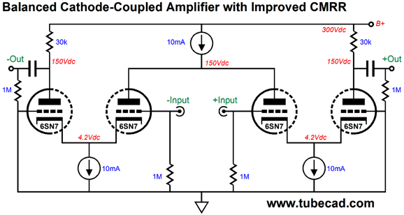
Now things get interesting. Imagine that we present both the inverting and non-inverting inputs with +1Vdc. What will happen? The output triode plates will not change in DC voltage and the input triodes will not alter their idle current! How is that possible? The coupled plates have only one path to the B+ voltage, which is through the added constant-current source. If both input see +1Vdc, the input triode plates will fall by mu times 1V, or 20V, so the plates will sit at 130Vdc, rather than 150Vdc. Conversely, if both input see -1Vdc, the input triode plates will rise by mu times 1V, or 20V, so the plates will sit at 170Vdc. Since the output triode plates will not change in DC voltage, we have achieved an excellent CMRR. By the way, this technique will not work with pentodes or FETs or transistors—only with triodes. Why? Plate resistance and, by extension, amplification factor. Triodes exhibit a relatively low plate resistance, which means that a change in plate voltage results in a surprisingly large change in current conduction. This is not true of FETs, as once their drains move beyond the FET's triode region, the FET is indifferent to changes in drain voltage, which is why they make such fine constant-current sources. The next problem we must overcome is poor PSRR. My solution is to use two Aikido cathode followers.
The added constant-current source must withstand high voltages, which means that an LM334 or LM317 won't cut it. Here is one possible circuit.
The MJE5852G PNP transistor can withstand a 400V collector-to-emitter voltage. Here is the complete circuit.
Note that each side gets a negative feedback loop. The gain is set to about +10dB, not much in other words. Why? Most balanced signal sources run hot from my experience, so little gain is needed. Four tubes are needed per channel. Yes, this is a lot of tubes, but it is also a lot of performance. In my last post, I mentioned that I needed to start using three icons, so that I could label schematics as being either textbook examples or modifications of the standard circuit or an altogether new circuit. Well, I could add a few more icons, for example, one for performance and another for expense. The above circuit, wrapped in luxurious metal work, powered by a regulated power supply, would garner rave reviews from the audio press and sport a $5,000 price tag.
For many newbies, all tube circuits are equal. They aren't. My issue with sonic ratings is that I hate all the hype in high-end audio and I do not want to throw any tube circuits away—even the SRPP. Thus, I rather not proclaim too much enthusiasm or too much scorn. Moreover, I know that many believe that they do not need to waste their time with anything less than the best. Really? In many applications, silver if often better than gold. In spite of the popular notion that you are only as exalted as is your consumption, the truth is that you must understand why the less-than-the-best is less, before you can understand why the best is the best. As Plato wisely pointed out:
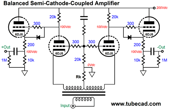
In other words, I won't be using the above icons. Well, at least not the sonic bells. Another approach to building a balanced cathode-coupled amplifier is the following.
The assumption here is that the signal source, say an external DAC, offers an XLR balanced output, which means that the signal source was designed to drive a 600 ohm load. The 1:1 signal transformer is a 600-ohm : 600-ohm type. The word "semi" appears in the circuit title because this circuit only half counts as a cathode-coupled amplifier. The two cathodes are sort of tied together as they share the same cathode resistor. On the other hand, the input impedance is very low, whereas a true cathode-coupled amplifier offers a hugely high input impedance. Resistor Rk's value wasn't specified, as it would depend on the DCR of the transformer's secondary winding. The tubes are 6DJ8 types, but other high-gm tubes, such as the 5687 and ECC99, could be used. The input impedance presented at each cathode is equal to Zin = (Ra + rp) / (mu + 1) where Ra is the plate resistor; rp, the triode's plate resistance; and mu, the triode's amplification factor. Aikido mojo is in play with the two-resistor voltage divider that terminates into the B+ connection. All in all, an interesting circuit. //JRB
If you enjoyed reading this post from me, then you might consider becoming one of my patrons at Patreon.com. So far, 16 patrons are helping out. Join the group today.
Next Time
User Guides for GlassWare Software
For those of you who still have old computers running Windows XP (32-bit) or any other Windows 32-bit OS, I have setup the download availability of my old old standards: Tube CAD, SE Amp CAD, and Audio Gadgets. The downloads are at the GlassWare-Yahoo store and the price is only $9.95 for each program. http://glass-ware.stores.yahoo.net/adsoffromgla.html So many have asked that I had to do it. WARNING: THESE THREE PROGRAMS WILL NOT RUN UNDER VISTA 64-Bit or WINDOWS 7 & 8 or any other 64-bit OS. I do plan on remaking all of these programs into 64-bit versions, but it will be a huge ordeal, as programming requires vast chunks of noise-free time, something very rare with children running about. Ideally, I would love to come out with versions that run on iPads and Android-OS tablets.
//JRB
|
|
Kit User Guide PDFs
Only $12.95 TCJ My-Stock DB
Version 2 Improvements *User definable Download for www.glass-ware.com |
||


| www.tubecad.com Copyright © 1999-2016 GlassWare All Rights Reserved |