| John Broskie's Guide to Tube Circuit Analysis & Design |
19 June 2016
Constant Power
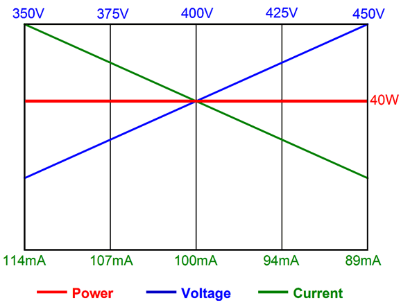
Effectively, the single-ended amplifier is much like a car whose idle speed is set to 5,000 RPM—fuel efficiency and excess clutch wear be damned. Now imagine that this car’s idle speed varied from day to day, depending on the weather, falling to a slow and safe 4,000 RPM on cold days and climbing to a fast and dangerous 6,000 RPM on hot days. Sad to say, but most single-ended power amplifiers are a lot like that car. For example, say the amplifier’s idle current was set to 100mA at the factory, where the wall voltage ran a cool 113Vac; but your wall voltage runs a hot 123Vac, so the idle current rises to 109ma, which might exceed the output tube’s specified steady current limit. Worse, due to the hot wall voltage, the amplifier’s factory expected B+ voltage of 400Vdc is now 435Vdc, so the output stage nominal 40W dissipation is now a hot and dangerous 47.4W. Not good. Of course, this problem may go in the opposite direction, wherein your wall voltage runs cool, so the expected 100mA drops to 91mA, which combined with the lower B+ results in less power to your speakers, although you could expect the output tubes to last longer. What we need is a constant-power single-ended output stage, one that maintains a fixed power tube dissipation. I created such an amplifier in the early 1990s and I revealed the circuit back in June of 2000 in an article titled, Design Idea: A Constant Power Output Stage. Here is an old-style schematic from that article.
It hurts my eyes to look at it now. Since it is fun, although shameless, to quote one's self, here is a quote from the article:
Hey, John, since you already covered this topic 16 years ago, why do it all over again? Are you running out of new ideas? My 2000 article only covered fixed bias single-ended constant-power amplifiers, not the cathode-biased version. As for running out of new ideas, a politician would sooner run out of lies than I would run out of ideas. Do not forget that I do plan on hitting post number 1,000 before I die. (Maybe, I will be like those old gents who live to see their 100th birthday and then die the next day. Mrs. Winchester, the wife of William Winchester, the maker of the famous repeating rifle, was told by her psychic medium that as long as her mansion remained unfinished, she would live on and on and not die by the preternatural hands of the ghosts slain by her late husband's guns. Her house remains unfinished; her remains rest in New Haven, Connecticut next to her husband's.) We all know what words “constant” and “power” mean, right? “Constant” has three meanings, but we are only concerned here with the dictionary’s second definition: Unchanging in nature, value, or extent; invariable. And “power,” as a noun, offers at least 16 definitions, but the only one we care about here is the following: The product of applied potential difference (i.e. voltage) and current in a direct-current (DC) circuit. (AC power is much more complicated.) In short, we desire a constant idle power dissipation by the output tube(s).
Thus, in order to maintain a constant power dissipation by the output tube, if the B+ voltage falls, the idle current rises; if the B+ voltage rises, the idle current falls; the heat dissipated at idle therefore remains constant. (While music is playing, the single-ended output stage actually cools, as power is diverted to the speaker.) This constant-power arrangement does not mean constant output power available for the loudspeaker. If the wall voltage falls, the output power to the speaker, paradoxically enough, may actually climb. If the wall voltage climbs, the output wattage will definitely fall. Interestingly enough, an output transformer's goal is a constant available output wattage, i.e. power, which is why they offer so many output taps, say 4-ohm, 8-ohm, and 16-ohm taps.
The above multiple taps allow the same amount of output power to be delivered into either 4-ohm or 8-ohm or 16-ohm load impedances.
The example above, the output transformer ensure that 4W is delivered into the three loud impedances, 4, 8, and 16 ohms. Most solid-state power amplifiers do not sport output transformers, alas. Without the output transformer, a 100W solid-state amplifier might deliver 200W into a 4-ohm loudspeaker (if its output stage can sustain the required increased current flow), but only 50W into a 16-ohm speaker, as its output swing becomes voltage-limited. It may appear as a bonus that the amplifier delivers more power into the 4-ohm speaker, but often we pay the price of excessive heat dissipation from the amplifier and, with it, potential damage to the output stage. Why don't solid-state amplifiers use output transformers? Cost—very high added cost due to the transformer itself and the required more robust chassis and the resulting added weight which incurs added shipping costs —explains about 99% of the story. If quality output transformers were cheaper than big heatsinks, most solid-state amplifiers would contain them. And if more solid-state amplifiers held output transformers, extremely-low-impedance loudspeakers would be more common, such as 1-ohm ribbon speakers. (Interestingly enough, it would be easier to design a good output transformer for a solid-state amplifier than it is to design one for a tube amplifier, as the winding ratio would be so much lower, only having to go from 16-ohm to 4-0hm, i.e. 2:1, rather than 5k to 4-ohm, i.e. 35:1. Moreover, inductive devices, such as chokes and transformers, and unlike capacitive ones, love low impedances.)
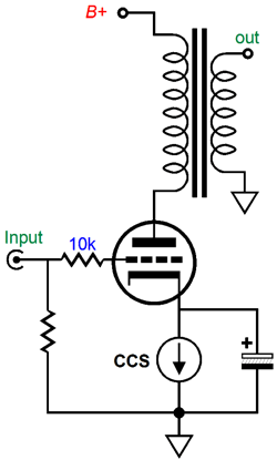
Note how as the impedances rise, so, too, rises the peak voltage swing, but the peak current swing falls. Note how multiplying the peak voltage swing by the peak current swing always equals 200W peak watts. Okay, now that we are clear about what constant power dissipation by the power tube means, how do we get there? Your first guess might be to use a constant-current source to auto-bias the output tube.
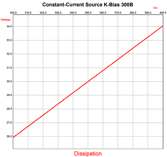
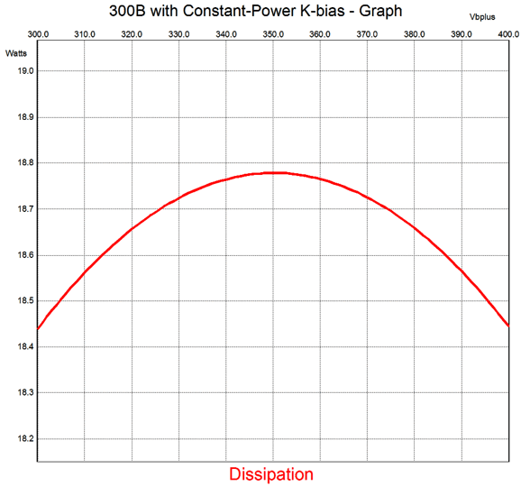
While this is not a bad idea, indeed it is a good idea, it will not get us to constant output tube dissipation. The SPICE-generated graph below shows the 300B's plate dissipation versus B+ voltage with its cathode loaded by a constant-current source to auto-bias the triode.
The problem is that the constant-current source is unaware of what the B+ voltage is, or whether it is running cold or hot, so it continues to conduct is fixed current, when what it needs to do is vary the current.
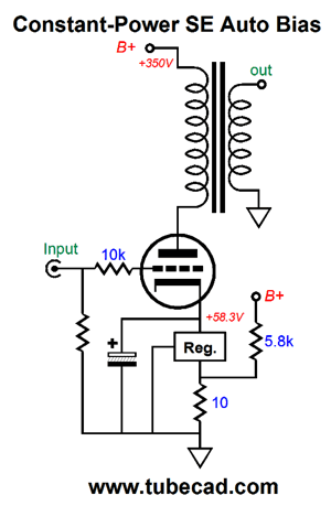
I really should have pasted an unhappy face on the above schematic. Why? It works, as it ensures a constant-power dissipation by the 300B tube, but it also wastes a huge gob of current through the 5.8k resistor, which will dissipate 21W at idle.
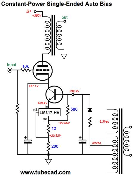
Of course, in the world of high-end audio, no idea is too silly or too extravagant not to be advertised as a feature. The intelligent workaround is not to attach the extra resistor into the B+ voltage; instead, we can use a lower voltage power-supply rail that is not regulated, say a DC heater supply. One possibility would be to make use of the negative-bias-voltage tap on the power transformer's secondary (if there is one), as the output tube will be cathode biased the tap would otherwise be unused.
Note how the schematic just got more complicated. Do not panic. The 30Vac negative-bias-voltage tap rectifies up to 39.9Vdc in this example. This DC voltage then biases up the NPN transistor (say a MJE15032) and provides a sampling of unregulated DC voltage, which the 580-ohm resistor feeds into the output of the LM317-HV. The result is that if the B+ voltage falls, the idle current rises; if the B+ voltage rises, the idle current falls; thus, the heat dissipated at idle remains fairly constant. How well does it work?
With +/-50V B+ shifts, the dissipation only deviates by 0.4W. This not bad, considering that the example that used only a simple constant-current source to cathode bias the output tube resulted in a 4W change in dissipation due to the same +/-50Vdc B+ shifts. But, John, what if my power transformer does not hold a negative-bias-voltage tap? In this case, we must try something different. Our old friend the Bastode can be put to good use.
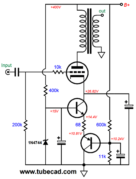
Once again, do not panic; it's not nearly as scary as it looks. The idea is simple: we use a 15V zener as a voltage reference for the NPN transistor and a two-resistor voltage divider to voltage reference the PNP transistor's base. The result is that if the wall voltage climbs up, the resulting higher B+ voltage will present a higher base voltage to the bottom transistor, which will result in a smaller voltage drop across the 68-ohm emitter resistor, so less current will flow through the output tube, which in this example is no longer a 300B, but a triode-connected EL34. In contrast, if the B+ falls in value, the voltage drop across the emitter resistor will increase, as will the current flow through the output tube. Magic. Note how two large-valued electrolytic capacitors are employed in this circuit. Could they be put to better use? Would I ask such a question if the answer was no?
Aikido Single-Ended Constant-Power
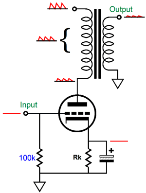
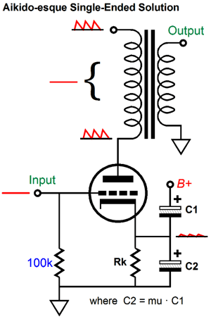
The triode's chief attribute, its low plate resistance, works against it in a single-ended output stage, as it creates a two-resistance voltage divider with the primary impedance bridging the power-supply noise to ground, which results in the noise being treated as signal and passed along to the output, as most of the noise appears across the primary. My workaround is the Aikido-esque single-ended solution, wherein a second capacitor is added atop the cathode resistor's bypass capacitor, so a small portion of the power-supply noise is purposely injected into the cathode, which results in the output transformer primary ignoring the power-supply noise, as the triode generates no variation in current flow due to the noise. No variation in current, no output signal from a transformer.
See Lowering the SE Amp's Output Noise, which first explained how to sidestep the poor PSRR; and my follow up in post number 308.
(As I now look at the above schematic, I see that we could retain a capacitor across the 11k resistor.) The top capacitor, C1, must be 1/mu as big as the bottom capacitor, C2. The punch-line here is that a triode can maintain a constant current flow in spite of an increase in plate voltage by two means: we can counter the increase in plate voltage by making the grid Vdelta/mu more negative or by making the cathode Vdelta/(mu + 1) more positive.
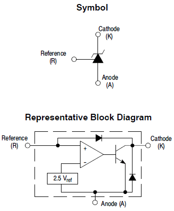
Thus, by making C2 mu times bigger than C1, the cathode will see a Vdelta/(mu + 1) variation in voltage, resulting in the power-supply noise being ignored, as the output tube will conduct a steady current in the face of the varying B+ voltage due to power-supply noise. What's not to like about the above circuit? Well, one thing is that the transistors exhibit a change in base-to-emitter voltage due to a change in temperature. Not good. Believe me, it gets plenty hot inside a single-ended power amplifier chassis. Of course, the larger the voltage drop across the shared emitter resistor, the less the contribution made by the changes in base-to-emitter voltage. Another approach would be to use a device that incorporates its own internal voltage reference, such as the shunt-voltage source the TL431.
This small three-pin IC is truly interesting as it can withstand a cathode voltage of 36V and it works from 1mA to 100mA. Moreover, its internal voltage reference is less temperature sensitive than the single transistors.
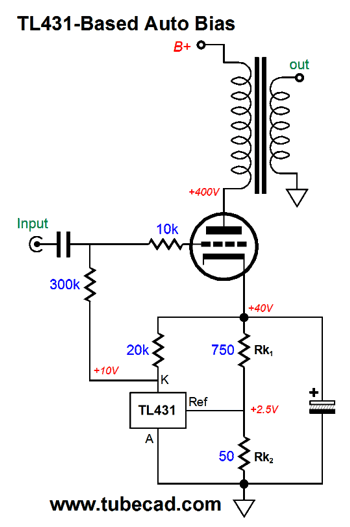
So, how do we use this little wonder? The TL431's reference pin strives to see 2.5V and it varies its cathode voltage to achieve this goal. So what we must do is to allow the TL431 to monitor the current flow through the output tube, and then allow it to adjust the grid-bias voltage so that the 2.5V voltage appears at the TL431 reference pin.
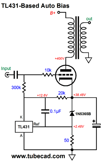
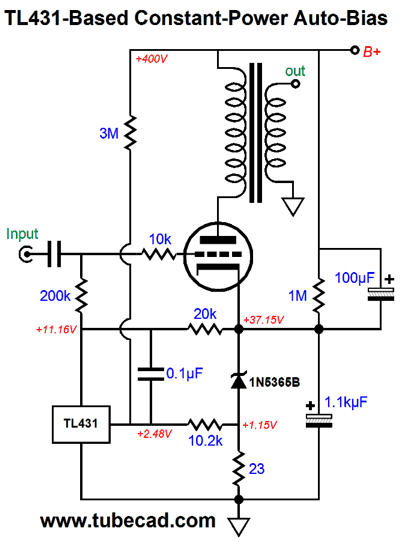
The triode sees a cathode-to-plate voltage of 360V and -10V of grid-to-cathode voltage. The bottom cathode resistor, Rk2, sees 2.5V of voltage drop, so the resistor experiences a current flow of 2.5V/50-ohms or 50mA. So does the triode idle at 50mA? No, not exactly, as the TL431 draws 30V/20k or 1.5mA; thus, the triode idles at 51.5mA of current flow. If the TL431's reference pin sees more than 2.5V, it will pull down its cathode voltage, which will decrease the triode's grid voltage, which in turn will decrease the output tube's conduction. Conversely, if the reference pin sees less than 2.5V, it will let go of its cathode voltage, which will increase the triode's grid voltage, causing an increase in the output tube's conduction. Auto-bias in a nutshell. We can replace the top cathode resistor, Rk1, with a zener, such as the 1N5365B, which is a 36V 5W device. In SPICE simulations, the following results obtained.
The 0.1µF capacitor was added to enhance stability. The large-valued electrolytic capacitor can be (and should be) bypassed by a quality film capacitor. Now, we can move on to constant-power operation.
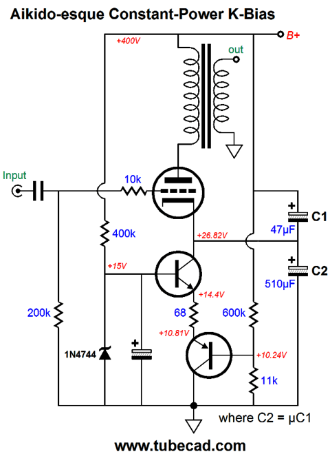
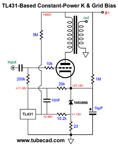
Note the added 3M and 10.2k resistors.(By the way, they do not make 1% 3M resistors, as far as I know; they do, however, make 1% 1.5M resistors, so two could be placed in series, which would prove safer, as few resistors are rated for more than 350V of voltage differential, no matter what the resistor's value.) The 1M resistor was added to give the TL431 circuit something to bite on while the triode is still cold and not conducting (I would actually use two 470k resistors in series). So, how well does this circuit work?
I missed the target plate voltage of 400V, as the plot centers at 405Vdc. More than good enough for government work.* Now is a good time to explain the logic behind the 3M and 10.2k resistor values. We begin with the 3M resistor. Take the B+ voltage, 400V in this example, then subtract the 2.5V reference voltage. Take the 397.5V of voltage and divide it by a large resistance, say 3M. The resulting current is 0.1325mA. This is the amount of current that must also flow through the second resistor. We want the voltage drop across both the second resistor and the cathode resistor to equal about half of the TL431's reference voltage of 2.5V, so about 1.25V. Divide 1.25 by 0.1325mA and we get about 9.43k; this is our target value for the second resistor. So, why did I use 10.2k instead? This is where engineering enters the game. The TL431's reference pin draws about 1.8µA of current, which throws the resistor values off. We must hold the 3M resistor constant, as we don't have any choice in high-ohmage values. Thus, we play around with the second resistor's value until we achieve our goal. In SPICE simulations, a 10.32k value was optimal, but the closest 1% resistor we can buy is a 10.2k resistor. Can you grasp how this circuit works? The TL431 wants to see 2.5V (2.48V in SPICE) at its reference pin. If the B+ voltage rises, then the voltage across the cathode resistor must fall, which is only possible if the idle current through the triode falls. Now that we have attained constant-power operation, how do we add some Aikido magic to improve the PSRR? The answer can be as simple as adding an extra capacitor.
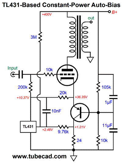
A triode-connected EL34 exhibits a mu of about 11, so the top capacitor must be 1/11th as large in value as the bottom capacitor. Or put differently, the bottom capacitor must be mu times bigger than the top capacitor. One problem we are likely to encounter is that the value marked on the capacitor is not likely to prove to be the capacitor's actual value. Most modern resistors are about 2% on the value, even when the resistor is marked as being a 5% type. In contrast, most electrolytic capacitors are accurately marked as 20%, as their values do scatter within that margin. Low-voltage electrolytic capacitors tend to run over their stated value, while high-voltage capacitors tend to run under. One workaround would be to forgo the capacitors altogether.
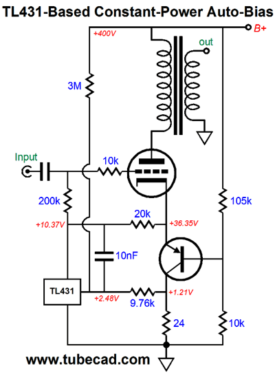
The zener has been replaced by a PNP transistor, say an MJE15033, which is a 50W, 250V, and 8A device in a TO-220 package. Using this transistor in place of the zener moved the resistor values closer to the expected values and yielded excellent results in SPICE simulations, as shown below. Once again, magic. Where is my MacArthur Fellows genius grant? (Oh, that's right: I am not delightfully diverse enough for such an award; or, perhaps, I am too diverse, but not in an orthodoxly delightful fashion.) John, John, John, do you not get it. These grants are intended for serious scientist types. Actually, dancers and poets receive the grants along with the less whimsical types.²
I should mention that we could use both resistors and capacitors to voltage divide the power-supply noise, much as we could wear both suspenders and a belt at the same time.
Note how the smaller-valued capacitor goes above the larger-valued capacitor, just the opposite of the resistors. So, are we done? No, of course not. We are never done, other than when we are dead, resting in our grave, having made our 1,000th post, as there are many more possibilities to be invented.
² MacArthur Fellows
Next Time
User Guides for GlassWare Software Since I am still getting e-mail asking how to buy these GlassWare software programs:
For those of you who still have old computers running Windows XP (32-bit) or any other Windows 32-bit OS, I have setup the download availability of my old old standards: Tube CAD, SE Amp CAD, and Audio Gadgets. The downloads are at the GlassWare-Yahoo store and the price is only $9.95 for each program. http://glass-ware.stores.yahoo.net/adsoffromgla.html So many have asked that I had to do it. WARNING: THESE THREE PROGRAMS WILL NOT RUN UNDER VISTA 64-Bit or WINDOWS 7 & 8 or any other 64-bit OS. One day, I do plan on remaking all of these programs into 64-bit versions, but it will be a huge ordeal, as programming requires vast chunks of noise-free time, something very rare with children running about. Ideally, I would love to come out with versions that run on iPads and Android-OS tablets.
//JRB |
Kit User Guide PDFs
And
High-quality, double-sided, extra thick, 2-oz traces, plated-through holes, dual sets of resistor pads and pads for two coupling capacitors. Stereo and mono, octal and 9-pin printed circuit boards available.
Designed by John Broskie & Made in USA Aikido PCBs for as little as $24 http://glass-ware.stores.yahoo.net/
The Tube CAD Journal's first companion program, TCJ Filter Design lets you design a filter or crossover (passive, OpAmp or tube) without having to check out thick textbooks from the library and without having to breakout the scientific calculator. This program's goal is to provide a quick and easy display not only of the frequency response, but also of the resistor and capacitor values for a passive and active filters and crossovers. TCJ Filter Design is easy to use, but not lightweight, holding over 60 different filter topologies and up to four filter alignments: While the program's main concern is active filters, solid-state and tube, it also does passive filters. In fact, it can be used to calculate passive crossovers for use with speakers by entering 8 ohms as the terminating resistance. Click on the image below to see the full screen capture.
Tube crossovers are a major part of this program; both buffered and un-buffered tube based filters along with mono-polar and bipolar power supply topologies are covered. Available on a CD-ROM and a downloadable version (4 Megabytes). |
||||||||||||||||||||


| www.tubecad.com Copyright © 1999-2016 GlassWare All Rights Reserved |