| John Broskie's Guide to Tube Circuit Analysis & Design |
04 July 2007 Hybrid Feedback/Feedforward Regulators The idea here is that we can wed two dissimilar technologies (solid-state and vacuum-state) and two different shunt techniques (feedback and feedforward) into one high-voltage regulator. In the schematic below, the vacuum tube does the shunting and it handles the high-voltages and high heat dissipation; the IC OpAmp provides the low-noise and high-gain amplification needed to drive the feedback loop; and the zener diode establishes the OpAmp’s power supply voltage and defines the internal voltage reference used by the regulator to maintain a fixed output voltage.
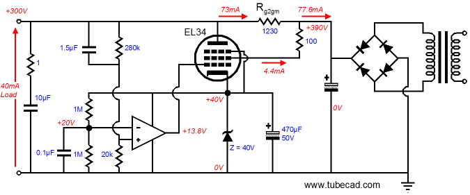
Note how the 280k and the 20k resistor set the output voltage and present the negative feedback to the OpAmp. Wait a minute, the connection is at the OpAmp’s positive input, not its negative input. True, which is as it should be, as the pentode inverts the signal it receives from the OpAmp, so viewed as a totality, the OpAmp’s positive input effectively becomes the regulator’s negative input. Wait a minute, there’s a 1-ohm resistor in series with 10µF capacitor at the regulator’s output. This resistor is essential in reality and even in SPICE, which is reassuring. I have designed and built many high-voltage regulator in my life and I have always been struck by how cheap parts often work so much better than the expensive alternative. For example, if a twenty-year old electrolytic capacitor is attached to the output, the regulator will probably prove stabile. On the other hand, if a new fancy high-frequency electrolytic capacitor or a film capacitor is placed across the output, watch out, as the regulator will oscillate wildly. Why? The regulator’s falling feedback ratio with frequency increase creates effectively an inductive element, which in parallel with a capacitance creates a resonant circuit. Adding the 1-ohm resistor gives the regulator something resistive to bite on and stabilizes the output. So have we arrived: is this the perfect high-voltage regulator? Well, it depends. If you live where the wall voltage remains fixed, never slipping or climbing, then this regulator will work handsomely. If, on the other hand, your wall voltage no more stable than a South American currency, then the regulator will run into trouble. You see this regulator strives to maintain a fixed output voltage, which means that when the raw B+ voltage falls, the pentode must lower is conduction to allow the output to remain constant; but when the B+ voltage climbs, the pentode must increase its conduction to pull the output voltage back in line, which greatly heats up the pentode, maybe dangerously so. There a few workarounds. The first is to use a super-powerful pentode, say a KT100. Second, we could place a pre-regulator in front of the shunt regulator, say a capacitance multiplier (an emitter-follower circuit). A third option is to forgo the DC regulation and be content with stellar AC regulation.
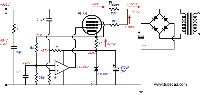
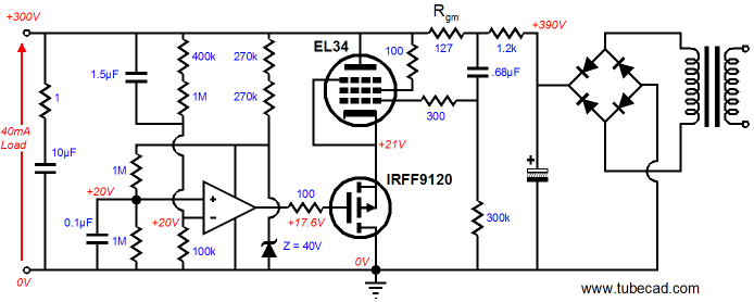
In the above schematic, we see a FBFF hybrid voltage regulator that ignores the output’s DC voltage; instead, it concerns itself with maintaining a fixed DC current through the shunting pentode and eliminating any noise from the output voltage. This circuit strives to establish a fixed 1V across the 27-ohm cathode resistor, which in turn defines a fixed Dc current through the resistor and the pentode. Any AC disturbance on the output is relayed to the OpAmp’s input, whereupon the OpAmp’s high gain will work to counter the noise at the regulator’s output by increasing and decreasing the pentode’s conduction. Note how the zener diode, which had established the voltage reference for the first FBFF regulator’s output voltage, in this regulator sets the voltage reference for the voltage drop across the 27-ohm cathode resistor. The following circuit works quite a bit differently from the first two circuits. Here the feedforward shunt regulation is fed to the pentode’s grid, not its screen. Here the feedback shunt regulation uses a P-channel MOSFET to drive the pentode’s cathode. Note that the OpAmp’s inverting input is used to receive the feedback signal, no its positive input. Also note that the DC output voltage is fixed in this regulator. Interesting. But why bother with it? By using the pentode’s grid as the feedforward shunt regulator’ input, a small-valued resistor can be used, which means we gain a good deal of flexibility, as the second series resistor (1.2k in the above schematic) can be made arbitrarily large or small, whereas the series resistor’s value was fixed in the first two FBFF regulators, as it had to equal the inverse of the pentode’s screen transconductance. So let’s say that we have a raw power supply that offers 560Vdc; now, the second series resistor can be made huge to absorb the extra voltage. Or this resistor can be left out altogether, if we limit the regulator’s scope to just AC regulation, not DC.
So have we arrived: is this the perfect high-voltage regulator? Well, it depends…. One thing that troubles me is that this circuit was the hardest to get SPICE to like and I am not confident that it would work off the schematic into reality without a lot of tweaking. Nonetheless, it is interesting, particularly the ground-grid amplifier aspect of the MOSFET’s source driving the pentode’s cathode. (This circuit is not a cascode!) In other words, I would build the second circuit first. Although I love DC regulation, its price might be too high for most to pay. As always, if you assemble any of these circuits, please do send me the results to share with everyone. //JRB
|
|


| www.tubecad.com Copyright © 1999-2007 GlassWare All Rights Reserved |