| John Broskie's Guide to Tube Circuit Analysis & Design |
|
07 December 2014
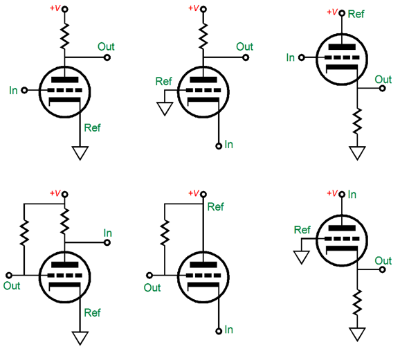
Basic Topologies
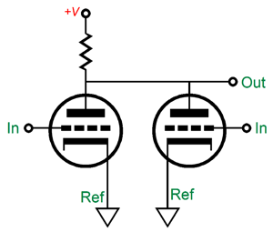
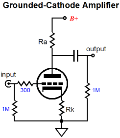
These six arrangements can then be combined to create more topologies. How many? More than you might imagine. For example, the first topology, the famous and ubiquitous grounded-cathode amplifier, can either cascade into another grounded-cathode amplifier, with the first grounded-cathode amplifier's output becoming the next grounded-cathode amplifier's input; or, the first's signal reference attaching to the second's output or its input; or, just be placed in parallel with another grounded-cathode amplifier, thereby creating a tube-based mixer.
Moreover, a grounded-cathode amplifier could connect to any of the other basic topologies in nine different ways for each topology. In other words, with just two triodes, we can come up with a bunch of novel circuits. With three or four triodes available to us, the number of possible arrangements becomes truly staggering. Throw in a pentode or FET and the mind reels from the vast number of possibilities. Of course, most tube fanciers only know two basic topologies: the grounded-cathode amplifier and the cathode follower. Indeed, many tube fanciers eschew any concern over alternate topologies. Apparently, if the grounded-cathode amplifier was good enough for their grandfather, it's good enough for them.
(I guess that the statute of limitations has run out on the following story, so I can tell it now. About a decade ago, I received an e-mail from a maker of high-end tube gear, asking for my help with their latest design, as the solid-state, floating, high-voltage regulator didn't regulate. As I scrutinized the schematic, I not only spotted the error in the power supply, but an error in the tube-based amplifier circuit as well. I wrote back, explaining not only how to fix the regulator but also how to side step the additional error. I pointed out that the circuit was internally at odds with its overall function, as two of the four stages within their design fought each other; and that by simply transposing the two stages, the entire amplifier would work much better. I also pointed out that since their product was point-to-point wired, my suggestion could be tested after five minutes of re-soldering. Well, I got back a huffy reply that stated that they did not "share my obsession, my near fetish, with topology," that they were concerned only with sonic performance, not trivial and academic topological minutia. I guess that they could not spare that extra five minutes. Mind you, they had contacted me, not the other way around; and that I gave my help freely, as in free of charge, but at the unspoken and unacknowledged expense of my time and effort, as just my drawing a corrected schematic took far longer than five minutes. If they had not contacted me, how long would it have taken them to find the solution? Perhaps, only five minutes, as someone else on the web might have helped them out; without the internet, I am inclined to think weeks or months. Interesting, but also depressing.)
Augmented Tube Unity-Gain Buffers
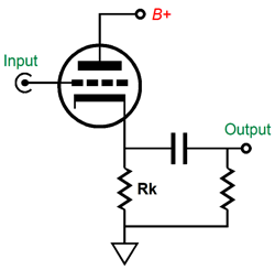
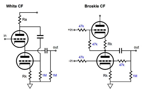
The cathode follower accepts its input signal at is grid and takes its output at its cathode. It offers a bit less than unity gain and a low output impedance. It is an intrinsically single-ended design, as it can only aggressively pull its output upward, and then release its hold, lessening its conduction, as its output swings negatively, allowing the cathode resistor to passively pull down. If we desire push-pull operation, we must add another active device, such as another triode or pentode or MOSFET... An example of such a push-pull buffer would be the White and Broskie cathode followers.
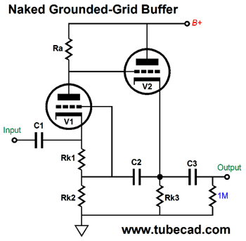
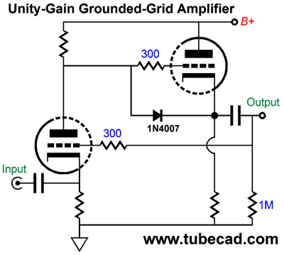
True class-A, push-pull buffering offers three advantages: lower distortion and half the output impedance (assuming that identical output devices are used) and up to twice the idle current into the external load; and more than twice the idle current, if you are willing to leave the confines of class-A. In contrast, a single-ended follower can only symmetrically offer up to its idle current into the load. But even if we stick to single-ended operation, we can still wring more performance from the simple cathode follower. For example, here is a compound circuit that uses both a grounded-grid amplifier and a cathode follower to create unity-gain buffer with increased performance, such as offering lower distortion and output impedance, yet remains entirely single-ended in operation.
Normally, the grounded-grid amplifier presents a low input impedance, but not this time, as capacitor C2 bootstraps the cathode resistor Rk1 by connecting in AC terms to the output, which raises the input impedance. How is that possible? Remember, the grounded-grid amplifier does not invert its input signal at its output. Thus, a positive input signal will cause the grounded-grid amplifier's plate voltage to climb, which in turn will cause the cathode follower's cathode to climb, which means that the signal present at the junction of resistors Rk1 and Rk2 will come close to equaling the signal present at the top of resistor Rk1. In other words, much higher input impedance than you might expect.
When presented with a new circuit, you should always ask yourself if the added complexity is worth it. For example, ask yourself if this buffer would offer better performance that just two triodes placed in parallel, which would halve the output impedance and lower the distortion a bit. For example, with V2 being a 6DJ8 or 5687 or ECC99, we would expect an output impedance of about 100 ohms, so two triodes would deliver an output impedance of about 50 ohms. Well, let's flesh out the circuit and use a 12AX7 and an ECC99. What is its output impedance? About 2 ohms is the answer. In other words, about 50 times better than a single ECC99-based cathode follower would deliver and 25 times better than two ECC99 in parallel could yield. Not bad. The gain come close to unity, with an output that follows the input by 99.2% (or -0.07dB, with true unity gain being 0dB). The 1N4007 diode protects the EC99 at turn on, as it prevents its grid from being 200V more positive than its cathode. True, the internal coupling capacitor is rather large in value, at 10µF. "If only we could lose this capacitor," is what I hear many readers thinking to themselves. Well, we can.
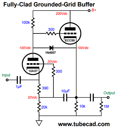
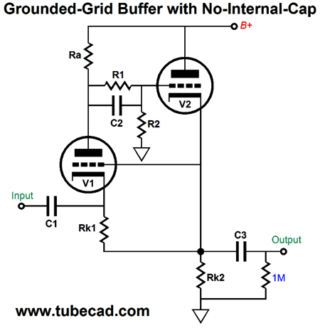
In the above schematic, we still see an internal coupling capacitor being used, but it can be 100 times smaller in value, as 10µF is 100 times bigger in value than 0.1µF. Okay, lets dress this circuit up a bit.
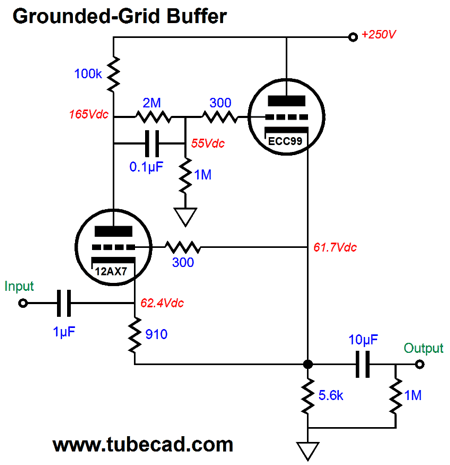
Once again, we use a 12AX7 and an ECC99. The 2M and 1M resistors define a two-resistor voltage divider that thirds the DC voltage present at the 12AX7's plate before passing it o to the ECC99's grid, which allows us to DC couple the 910-ohm cathode resistor to the ECC99's 5.6k cathode resistor. The 1µF input coupling capacitor is perhaps a tad bit too small in value, but I wanted to emphasize the relatively high input impedance.
For additional information on the grounded-grid topology and circuits like the one above see blog post number 312.
Augmented SRPP Buffers
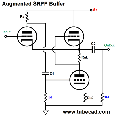
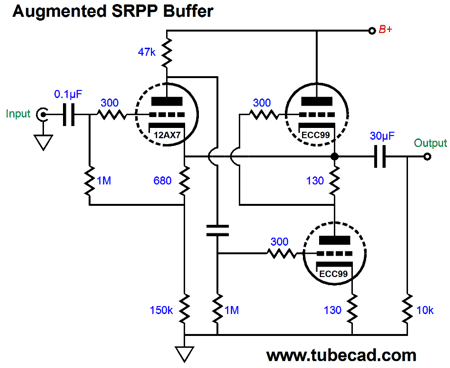
The input tube is configured as a grounded-cathode amplifier, but its cathode actually "grounds" into the SRPP's output. In other words, 100% negative feedback. For example, imagine a positive-going pulse applied to the output. The pulse would make the input triode's cathode even more positive than its grid, so a large positive pulse would appear at the input triode's plate, which in turn would be relayed to the bottom SRPP triode's grid, causing the bottom triode to greatly increase its conduction, pulling the SRPP's output downward, thereby countering the externally applied pulse. Another way of looking at it is to see that the input triode is constantly comparing the input signal present at its grid to the output signal present at its cathode. If there is difference, the input triode's plate moves in the opposite direction, which causes the SRPP output stage to move its output in line with what the input triode's grid sees. One problem we might encounter is that the input triode's current flows through the sense resistor, Rak, and the SRPP's bottom triode. One workaround is to give the input triode its own cathode resistor.
Now that we have fixed that problem, we still face another: biasing the input triode, which will not be easy with the DC connection of its cathode to the SRPP's output. For example, say the SRPP's output centers at 100Vdc at idle, but we applied a bias voltage of only 80Vdc to the input triode's grid, causing the input tube to cutoff. Not good. The workaround is to use an input coupling capacitor and an extra cathode resistor.
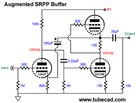
Or, we could go in the other direction and use a coupling capacitor to connect the input triode's cathode to the SRPP's output.
An added advantage to the above circuit is that the input is now at ground level. Moreover, the input triode gets a lot more plate voltage to work with, which with a high-mu triode, such as the 12AX7 or 5751, can only help. Since small-signal triode usually come two to the tube envelope, such as the 6H30, 6DJ8, 6SN7, 12AU7, 12AX7, 5687, ECC99… we can use the second triode in the input stage.
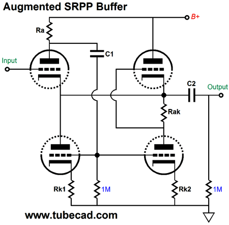
Well, to be more precise, in the output stage. Note how both bottom triodes work to drive the output. The left bottom triode functions in White cathode follower topology, while the right bottom triode functions in an SRPP topology. Yes, both topologies are in parallel with each other. Very interesting, no?
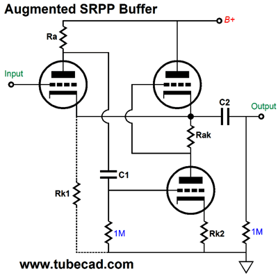
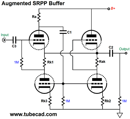
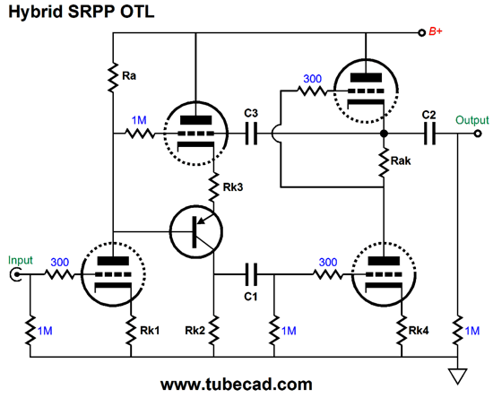
The above variation looks like two SRPP circuits in parallel, but it is not so, as the left bottom triode still functions in White cathode follower topology, as resistor Rk1 does not function as an AC current-sense resistor, but resistor Rak does. So why is resistor Rk1 there? It allows the input triode to bias correctly, as it functions as DC current-sense resistor. I will end this SRPP-filled section with a hybrid SRPP OTL amplifier.
The PNP transistor and the triode above it define a Bastode circuit, which some refer to as an inverted cascode. The transistor's base receives its input signal from the triode's plate, which it then relays to to the triode above it through resistor Rk3. Capacitor C3 AC couples the output signal to the triode above the transistor. If the output signal fails to match the signal the transistor's base sees, resistor Rk2 sees the amplified error signal, which is then passed on to the SRPP stage. In other words, we have a negative feedback loop, but one that does not extend to the input stage. If we wanted to, we could use the inverting-amplifier feedback configuration by adding one resistor, which would span from the input triode's grid to the output.
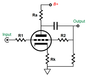
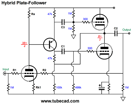
Plate Followers
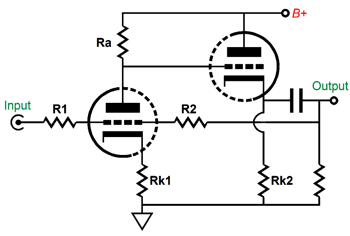
Making an augmented plate follower requires adding more active devices. The next circuit includes the easiest addition: an extra triode configured as a cathode follower. Since the negative feedback loop encompasses the cathode follower, the cathode follower's output is under the control of the input triode. The result is a much lower output impedance and lower distortion. An added benefit is that, if resistors Ra and RK2 equal each other, the circuit functions as a constant-current-draw buffer, which greatly unburdens the power supply, as the power supply does not "see" the signal; in turn, this means that the other channel does not "see" the other channel's signal either.
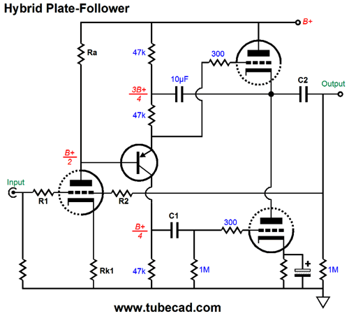
We could replace the cathode follower with a White cathode follower, but not an SRPP, as the SRPP inverts the signal phase. But instead let's do something bolder, such as using a transistor-based split-load phase splitter.
Note how the entire buffer circuit inverts the input signal at its output. Also note how the 10µF capacitor couples the output signal to the phase splitter, thereby ensuring equal drive for top and bottom output triodes. Because the 10µF capacitor must be large and expensive, I created the following variation.
Note how the output still attaches to the phase splitter. Also note how the output stage is centered by the two 1M resistors in series. Which version would work better? I am inclined to think that the latter one would. By the way, the first version employs a hidden Aikido-like technique to null the power-supply ripple at its output. So, I could be wrong about which would work best; or, put differently, it depends on how good the power supply is.
Next Time
User Guides for GlassWare Software
For those of you who still have old computers running Windows XP (32-bit) or any other Windows 32-bit OS, I have setup the download availability of my old old standards: Tube CAD, SE Amp CAD, and Audio Gadgets. The downloads are at the GlassWare-Yahoo store and the price is only $9.95 for each program. http://glass-ware.stores.yahoo.net/adsoffromgla.html So many have asked that I had to do it. WARNING: THESE THREE PROGRAMS WILL NOT RUN UNDER VISTA 64-Bit or WINDOWS 7 & 8 or any other 64-bit OS. I do plan on remaking all of these programs into 64-bit versions, but it will be a huge ordeal, as programming requires vast chunks of noise-free time, something very rare with children running about. Ideally, I would love to come out with versions that run on iPads and Android-OS tablets.
//JRB
|
|
I know that some readers wish to avoid Patreon, so here is a PayPal button instead. Thanks. John Broskie
Kit User Guide PDFs
Only $12.95 TCJ My-Stock DB
Version 2 Improvements *User definable Download or CD ROM www.glass-ware.com |
||


| www.tubecad.com Copyright © 1999-2011 GlassWare All Rights Reserved |