| John Broskie's Guide to Tube Circuit Analysis & Design |
15 March 2008
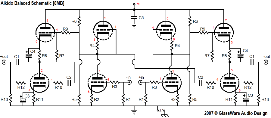
Balanced Aikido (It's ironic: I decided to save on the setup fees incurred with each new PCB layout by populating a huge PCB panel with 11 new boards. In other words, I would pay only about a $27 setup fee per new board design, as $300/11 roughly equals $27; which is quite a bit cheaper than $3,300 worth of setup fees for 11 panels, with one board per panel. Well, the only problem was that designing 11 new boards at the same time was overwhelming, as 5,000 traces were needed and my 52-year-old brain cannot keep up with 11 different R1s and C1s.… So, while I did save on setup fees, I have fallen way behind in actually releasing the boards for sale, which no doubt has cost more than the saved fees.)
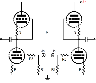
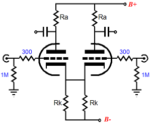
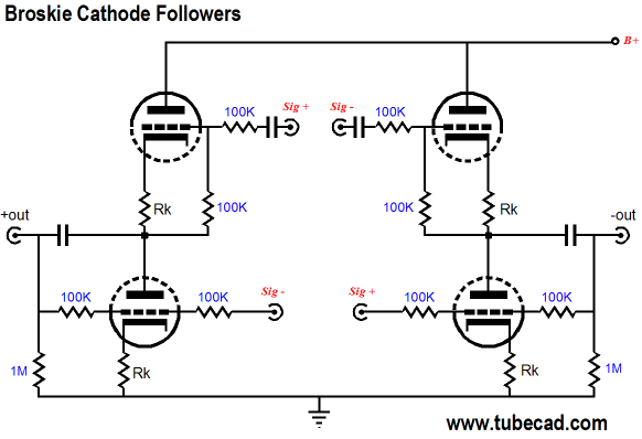
The above circuit is an interesting one, in that it does not use a differential amplifier at its input. Instead, this balanced line stage amplifier employs two grounded-cathode amplifiers, with symmetrical loading by the same triodes, as used in the first half of the Aikido amplifier. (The circuit uses pure single-end operation with not a speck of SRPP, all appearances to the contrary.)
And since there is no differential amplifier, with its long tail—its large valued common cathode resistor—there is no need for a negative power supply rail. I know that many tube fanciers will breathe a long sigh of relief upon reading this, as many tube-loving solder slingers just hate negative power supplies. But before we move on to the rest of the circuit, let’s examine why a differential amplifier is used as the input circuit in most balanced amplifiers.
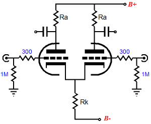
Differential Amplifiers
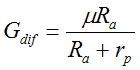
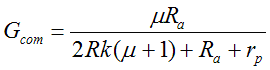
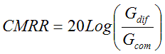
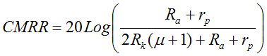
The differential amplifier is a simple circuit that holds two triodes (or pentodes, transistors, FETs, MOSFETs, heptodes…) and two plate resistors, but only one common cathode resistor. When a balanced signal is applied to the two grids, one triode conducts more, while the other conducts less, thereby creating balanced output signals at the triodes’ plates. The formula for this amplifier’s gain is a simple one: (This is also the formula for a grounded-cathode amplifier with a bypassed cathode resistor or with a grounded cathode and fixed bias.) But what happens when the input signal is not balanced, when both grids see the same signal in the same phase? Then the differential amplifier offers very little gain indeed, as the formula below—for gain with a common-mode input signal—reveals. (If you are troubled by the 2Rk in the denominator, imagine that the differential amplifier is made up of two grounded-cathode amplifiers being joined at the cathodes by connecting a wire from cathode to cathode, so that two cathode resistors have been placed in parallel, thereby halving their values.)
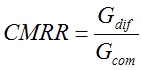
From inspecting the above formula, we readily see that the cathode resistor can make a huge difference in gain, as it is greatly magnified in value by the triode’s amplification factor. In fact, if an infinitely large-valued common cathode resistor is used, an infinitely small amount of gain results. Is this a good thing? Indeed it is. We want to amplify only the differences between the two input signals and reject and ignore all that is common between them, which—pretty much by definition—means noise. Thus, the bigger in value the common resistor is the better the common-mode-rejection ratio (CMRR). And thus, we see the popularity of replacing the common cathode resistor with a constant-current source. or in dBs: or as one easy formula:
Broskie Cathode Followers
Back to the Aikido Balanced Circuit Great. Wonderful. But how can I buy some of those shiny new PCBs or kits? Hang in there: I am still testing the the boards and I am also doing my taxes. In other words, until the taxes are done, nothing else can get done. This includes testing, writting user guides, adding products to the GlassWare Yahoo Store. But soon...or at least so I pray.
Next Time
//JRB
|
E-mail from GlassWare Customers And
High-quality, double-sided, extra thick, 2-oz traces, plated-through holes, dual sets of resistor pads and pads for two coupling capacitors. Stereo and mono, octal and 9-pin printed circuit boards available.
Designed by John Broskie & Made in USA Aikido PCBs for as little as $24 http://glass-ware.stores.yahoo.net/
The Tube CAD Journal's first companion program, TCJ Filter Design lets you design a filter or crossover (passive, OpAmp or tube) without having to check out thick textbooks from the library and without having to breakout the scientific calculator. This program's goal is to provide a quick and easy display not only of the frequency response, but also of the resistor and capacitor values for a passive and active filters and crossovers. TCJ Filter Design is easy to use, but not lightweight, holding over 60 different filter topologies and up to four filter alignments: While the program’s main concern is active filters, solid-state and tube, it also does passive filters. In fact, it can be used to calculate passive crossovers for use with speakers by entering 8 ohms as the terminating resistance. Click on the image below to see the full screen capture.
Tube crossovers are a major part of this program; both buffered and un-buffered tube based filters along with mono-polar and bipolar power supply topologies are covered. Available on a CD-ROM and a downloadable version (4 Megabytes). Download or CD ROM
|
|||


| www.tubecad.com Copyright © 1999-2008 GlassWare All Rights Reserved |