| John Broskie's Guide to Tube Circuit Analysis & Design |
| 14 May 2007 Cathode-Coupled Amplifier Developments
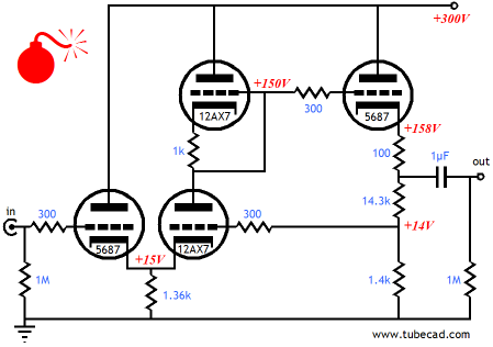
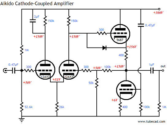
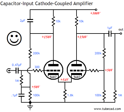
Wrong turn (Thus, I have placed a red bomb icon on the schematic shown at the top of the page...although, to be honest, the circuit would probably beat the pants of most high-end line stages, so the bomb icon was a bit too much. I will start labeling my schematics with an array of possible Wingding icons:
Wait minute, isn't the hand shape next to the unhappy face considered obscene in some cultures? This might require more thought on my part.) I assumed that circuit at the top of this page would prove a genuine winner. The circuit seemed to have so much going for it: only one coupling capacitor, no negative power supply, AC and DC feedback, a moderate final gain: a perfect wedding of low-mu/high-gm triodes with high-mu/low-gm triodes, with a 5687’s cathode passing the input signal to a 12AX7 at its cathode, while the 12AX7’s plate is loaded by 12AX7-based active load, the symmetrical loading working to lower distortion; as I put in blog 105, “symmetrical loading offers a countervailing twist to an already twisted active circuit element;” ending with a second 5687 triode, configured in a cathode-follower-based output stage, delivering a low-distortion and low-output-impedance. Well, everything is true, except the bit about the symmetrical loading offers a countervailing twist to an already twisted active circuit element. I ran some SPICE simulations to see how much improvement the active load delivered over a simple plate resistor. There was none; in fact, the resistor was quite a bit better. What went wrong? The symmetrical-loading trick has always worked quite well with grounded-cathode amplifiers—and with grounded-grid amplifiers. One possibility is that nothing went wrong, that the SPICE triode models are so far off, with their perfectly constant amplification factors, that the simulation’s results are not to be believed. It doubt that this is the answer. Yes, the SPICE models are weak and, at times, even silly, but usually the results are overly optimistic; besides they match reality when it comes to a symmetrically-loaded grounded-cathode amplifier, even if a tad over optimistically. No, when I stepped back and looked at the circuit, everything made sense—the simple plate resistor would have to be better. Understanding just why the resistor would be better is well worth our effort.
Cathode-Coupled amplifier & low distortion
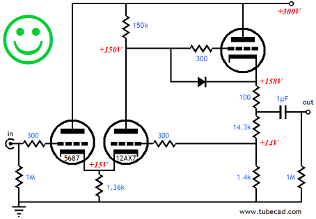
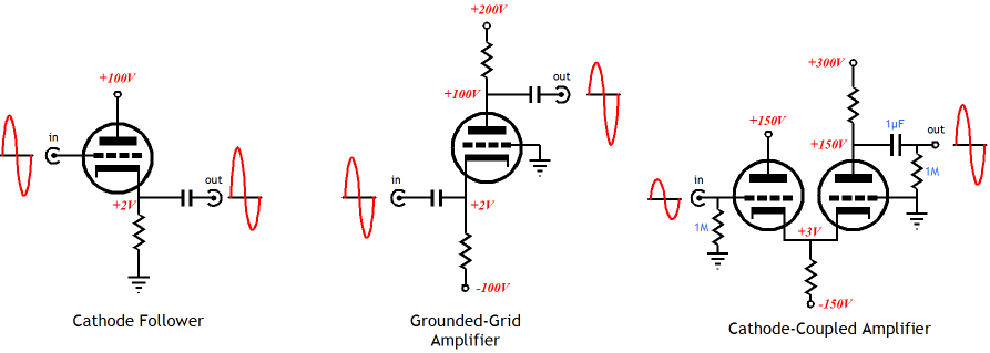
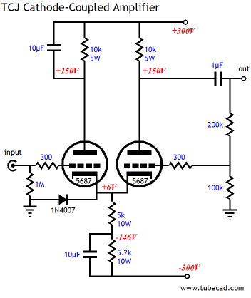
The cathode follower input stage distorts in the direction of bigger positive-going voltages than negative-going voltages. The grounded-grid amplifier output stage distorts in the opposite direction of bigger negative-going voltages than positive-going voltages. Why? Because both circuits rely on a triode that is easier to turn on than it is to turn off. Look at a set of plate curves and you will see the fairly straight grids that curve at the bottom of the graph. The curvature is the result of the triode not cutting off when it should, requiring more negative ground voltage than a perfectly linear device would to turn off. (In fact, sometimes the lines never touch the bottom axis. These triodes are abundant distortion makers, but they prove invaluable to misleading audiophiles about the nature of class-A operation. Imagine a keg of beer that continually leaked beer, no matter how hard you twisted the valve to its off position. What a pain, unless you are in marketing, as this “feature” can be exploited: "The new Super-Infinity-Keg keeps on pouring! It’s like owning your own brewery!" Imagine a blurry-eyed college kid saying, “Wow man! Infinite beer forever dude!” Well a low-current “class-A amplifier” based on dribbling output tubes is about as good as a beer keg with a leaky valve.) So, why don’t the cathode follower and the grounded-grid amplifier distort in the direction? Why opposite directions? They work in opposite current phase when presented with the same input signal. As the cathode follower conducts more, the grounded-grid amplifier conducts less, as its cathode is being made more positive than its grid, which yields the same result as making the grid more negative to the cathode. I know that some are thinking that what I have said so far is basically true, but not a lot true, as the cathode follower will distort much less than the grounded-grid amplifier, as it enjoys 100% degenerative feedback, which the grounded-grid amplifier doesn’t; besides, a cathode follower loaded with a constant-current source or a huge cathode resistor does not distort much at all—we have all seen the graphs in old electronic textbooks (Valley and Wallman's, Vacuum Tube Amplifiers, for example). There’s one problem with this rebuttal, but a vitally important problem: the cathode follower input stage of a cathode-coupled amplifier is not loaded just by a constant-current source or very large-valued cathode resistor, but also by the cathode that it drives; and this cathode presents a very low-impedance load indeed. The actual load presented by the grounded-grid amplifier’s cathode is Zk = (rp + Ra)/(mu + 1). Assuming a 6DJ8 with a 10K plate resistor, the impedance at the cathode is less than 400 ohms, quite less than the infinity that the constant-current source seemed to promise. Anyone who has ever tried to build a small OTL headphone amplifier using a single triode cathode-follower output stage will know just how much distortion a cathode follower makes into such a low load impedance. (Do not assume that the constant-current source is not a good idea, because it most certainly is.) So the cathode follower twists one way and the cathode input of the grounded-grid amplifier twist the other way, with the net result being fairly flat. Since we have already straightened out the two triodes’ combined output, there is no need to add an additional countervailing twist. In other words, the active load, made up of the same triode and a cathode resistor, is like putting on two pairs of eyeglasses and expecting to see twice as well. If the two triodes within the cathode-coupled amplifier work to cancel each other’s nonlinearity, shouldn’t we be using the same triode type in both positions? Good question. I know from experiments I performed decades ago that different triode types can still sum to linear, but finding the right pairs can be a daunting task, so using the same triodes is probably the safe bet. The problem of the dissimilar plate grid voltages returns. One solution is to use a coupling capacitor on the input and a DC reference voltage, as shown below.
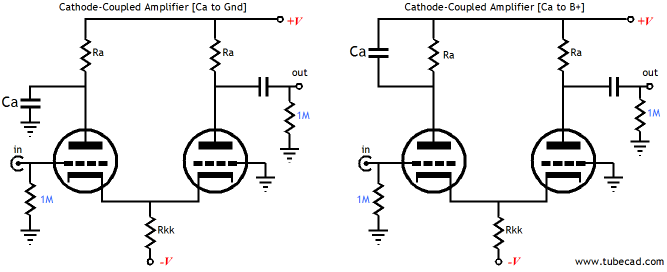
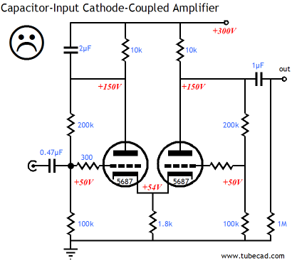
(A better choice than the 5687 might be the 12B4 or even a triode-connected power pentode, such as the EL86 or EL34 or 6V6.) While we are on the topic of figuring out how to get the most out of a cathode-coupled amplifier, we should look into small problem that almost no knows is a problem—namely, Should the shunting capacitor Ca terminate into ground or into the B+?
First of all, just using the capacitor and the extra plate resistor is rare enough, so this problem isn’t a problem for most solder slingers. The majority of schematics show the circuit on the left, with the capacitor attaching to ground. It seems the right thing to do, as this configuration will buffer the input cathode follower’s plate from the B+ noise (which, by the way, it then appears at the cathode-coupled amplifier’s output, although attenuated greatly). Good as that sounds, I prefer the circuit on the right, as it eliminates the output signal’s footprints from appearing on the B+ voltage. What? Ideally, we want the two current swings within the cathode-coupled amplifier to meet and null at the B+ connection. Terminating the shunting capacitor to ground shunts the cathode follower’s current swings into ground, not the B+ connection, leaving only the grounded-grid amplifier’s current swings to appear superimposed on the B+ voltage. (Because of the common-cathode resistor, the negative power supply rail sees a near constant current draw from the amplifier.) Any unbalanced current flowing through the positive power supply rail will superimpose a small signal on the rail voltage, making more work for the decoupling capacitors or voltage regulators in use. Admittedly, this is a small issue, but getting as many of the small issues right is what makes a masterpiece possible.
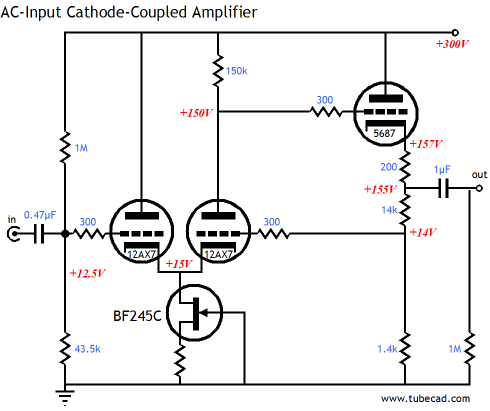
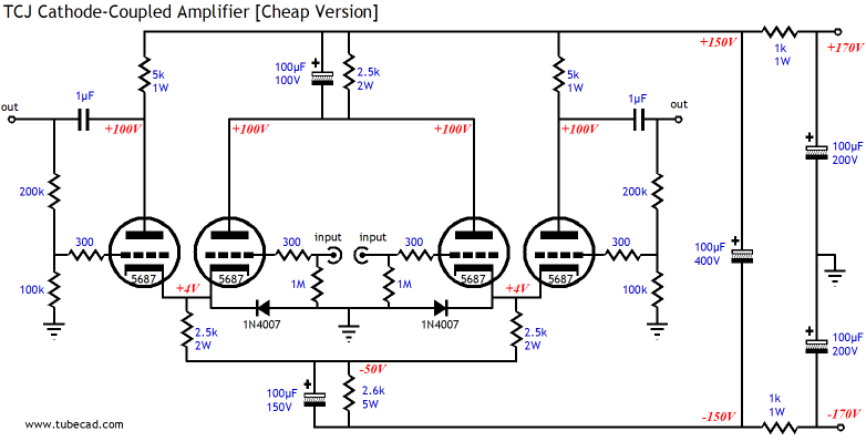
In the schematic shown above, we see several small tricks: the equalized plate voltage and idle currents, the shunting capacitor terminated into the B+ connection, the protective diode, the two-cathode resistors with one bypassed resistor that improves the PSRR, the feedback loop that sets a moderate amount of gain and a fairly low output impedance. The two-cathode resistors with one bypassed resistor is an Aikido-like technique that forces the triodes to undergo noise-induced current variations twice as large as normal, which then impose an anti-phase noise signal on the output signal, thereby nulling the power supply noise that would otherwise leak out. The only real hassle this line stage amplifier presents is the relatively high cost required to build the amplifier, as 5W and 10W resistors are not cheap (nor are high-voltage parts in general). Still, this amplifier could easily be point-to-point wired in an hour or two and would—undoubtedly—sound fantastic. Still a cheaper and easier version would be appreciated by many.
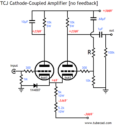
Two channels and more of the power supply are shown, which is why it may look more complex than it realy is. The rail voltages have been reduced by half. (±170Vdc can be derived from an isolation transformer’s 120Vac windings or a center-tapped 240Vac winding.) The idle current per triode has been reduced from 15mA to 10mA and all the corresponding resistor values and wattages have been updated. All in all, not a bad design for a stereo line stage amplifier; as a single-channel balanced line stage amplifier, however, it is much better, as all the currents null in the shared 2.5k and 2.6k resistors. (I would terminate the top shunting 100µF capacitor to ground, not the B+, if I were running a balanced input signal.) More than a few will be annoyed to see the global feedback loop. For these individuals, the following circuit offers a feedback-free operation, but without the added power-supply noise.
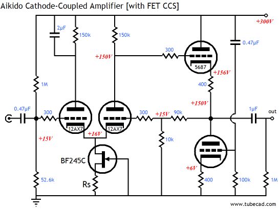
The critical resistor is R, as it sets the amount of power supply noise to inject into the output triode’s grid. Since a cathode-coupled amplifier (without a feedback loop) offers a very poor PSRR, any improvement will be welcome. With just a bit of tweaking, deep -60dB nulls are possible. The shortcut formula is to take the amplifier’s gain and then add 1 to the number, then multiply the sum against 10k. For example, with a gain of 8, use a 90k resistor. Very Aikido-like indeed. Speaking of Aikido-like techniques, here is an Aikido cathode-coupled amplifier.
Aikido cathode-coupled amplifier
The obvious upgrade is to use a constant-current source in place of the shared cathode resistor. Resistor Rs must be selected to yield an idle current of 2mA. If the input cathode follower is loaded by other cathode’s output impedance and the constant-current source impedance in parallel, is the constant-current source worth the extra effort? Yes. The constant-current source ensures that the maximum gain and lowest distortion obtain. I should mention that with the bipolar power supply circuits, the assumption made is that the two power supply rails share an equal magnitude of noise, but in anti-phase with each other. This assumption can prove wrong. In order for both power supply rails to perfectly track each other, the two rails must see the load impedances and current flows. This is where subtle minds are needed (or failing that a good SPICE program). For example, in the two circuits below, which topology offers a lower load impedance to the B+ rail? Which presents a lower impedance to the negative power supply rail? The answer to the first question is that the circuit on the left presents a load impedance equal to Ra. The answer to the second is that both circuits present the same load impedance (something of a trick question that last one).
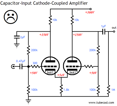
While we at the job of painting with finer strokes, I should mention that the shunting capacitor termination at the B+ as shown in the right circuit is not always best. For example in the two circuits below, it adds power supply noise to the input, as the two-resistor voltage divider presents one third of the power supply noise to the input grid. Depending on the volume control’s position and output impedance, the noise will mix with the input signal, which will be amplified in phase and appear riding on the output signal. Not a good plan.
Nor does terminating the shunting capacitor to ground work perfectly, as unbalanced signal currents will flow through the B+ connection. This unbalanced signal current will then develop a signal voltage on the B+, which will then leak into the other channel, making a once clean signal dirty and worsening the stereo perspective.
The solution is to keep the B+ connection for the capacitor and decouple the power supply noise from the amplifier’s input.
I also like this circuit quite a bit and am also tempted to make a PCB for it.
Next time
*Systematics is the science of systematic* classification. *Systematic means of, characterized by, based on, or constituting a system.
High-quality, double-sided, extra thick, 2-oz traces, plated-through holes, dual sets of resistor pads and pads for two coupling capacitors. Stereo and mono, octal and 9-pin printed circuit boards available. Designed by John Broskie & Made in USA http://glass-ware.stores.yahoo.net/ Now accepting
//JRB
|


| www.tubecad.com Copyright © 1999-2007 GlassWare All Rights Reserved |