| John Broskie's Guide to Tube Circuit Analysis & Design |
27 April 2008
New Hybrid SE OTL Design
AJ van Doorn's article, "Build a Hybrid SE OTL Amp," describes a novel circuit that directly couples a vacuum tube to the loudspeaker, while a solid-state power amplifier also directly couples to the output. The tube, in his example a pentode, receives the input signal and the solid-state amplifier slavishly follows the tube's lead. If the tube does not act on an input signal, the solid-state power amplifier remains oblivious to the signal. If the tube's output clips, the solid-state amplifier will trace horizontal lines. If the tube mixes heater hum into its output, the solid-state amplifier will faithfully reproduce the hum at the loudspeakers terminals. Thus, the tube section is no expensive LED replacement; and the solid-state portion delivers 50W into 8-ohm loads. To add to the this list of desirable features we must include a few laudatory adjectives to describe how stunningly attractive his amplifier is, as we can see from the cover picture above. Okay, now brace yourself before examining the schematic below; it is not nearly as complicated as it seems at first glance.
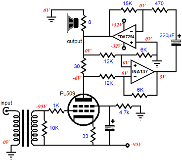
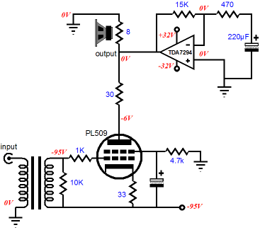
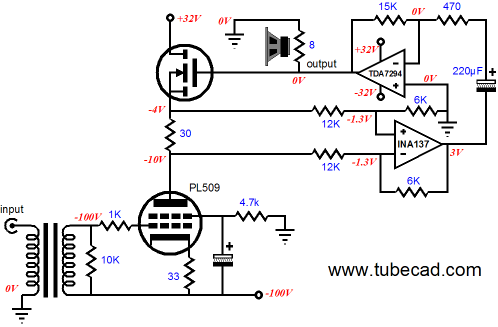
Let's begin at the top-left corner. Here we see an 8-ohm loudspeaker terminated into ground and connecting to the OTL's output. A TDA7294 power amplifier—which is much like the famous gain-clone power OpAmp, the LM3886—supplies all the needed heavy current swings into the loudspeaker and also feeds the tube, whose plate resistor attaches to the output and whose cathode resistor attaches to a 95V negative power supply rail. The output tube is a beefy PL509, and its screen finds a 4.7k resistor to ground (effectively, the tube's B+) and a large shunting electrolytic capacitor that terminates to the negative rail. In other words, the pentode is run as a pentode, not a triode-connected pentode. The tube's input grid is transformer coupled, to avoid coupling the negative rail's power-supply noise to the OTL's output. Any variation in current conduction through the tube is superimposed on its plate resistor, which in turn will create a variation in voltage drop across the plate resistor, which will be captured by the INA137 differential line receiver. This differential amplifier allows the plate resistor to tag along with the output voltage swing and not be tied to ground or a B+ voltage; it also allows only the variation in voltage across the plate resistor's leads to be measured and offered to the TDA7294 as its input signal. The TDA7294 is configured as an inverting amplifier and its input resistor is capacitor coupled to the INA137 differential line receiver's output, which allows the solid-state power amplifier to ignore the large DC offset from the INA137, while maintaining a low DC offset at the OTL's output, as the TDA7294's positive input is grounded and the power OpAmp will use all of its considerable DC gain to drive its negative loop, bringing the output DC offset inline with ground potential. That was quite a mouthful and I expect that it will be the differential line receiver that makes many scratch their heads but, trust me, it's not that complicated. Let's read what the good folks at Bur-Brown have to say about their INA137 differential line receiver:
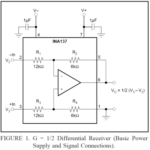
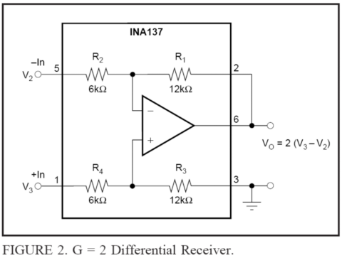
Impressive, indeed. The differential line receiver uses precisely matched resistors to measure voltage differences across its two inputs. The greater the internal OpAmp's gain and the tighter the tolerance of the resistor sampling and feedback resistors, the higher the CMRR. The INA137 holds two sets of 12k and 6k precision resistors and these resistors can be wired up in two ways: one with a gain of 2 (+6dB) and one with a gain of 0.5 (-6dB).
Mr. van Doorn has opted for the gain-of-one-half configuration shown in figure 1, as it allows the INA137 to see much larger voltage swings at its two inputs, twice what you might guess from its +/-15 power supply rail voltages.
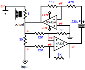
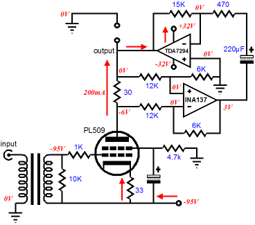
To see better how the differential line receiver reads the difference across the plate resistor, let's remove the tube and its supporting power supply and input transformer. Now the un-terminated end of the plate resistor will be used as the amplifier's input. Do not panic: the 30-ohm resistor does not define the input impedance of the amplifier. Rather, the TDA7294 power amplifier bestows a gain of 32, of which half remains (16) because of the -6dB (0.5) loss through the INA137, so the effective input impedance is closer to 500 ohms. Although this is low, it is not impossible to drive—besides, we are performing an audio-autopsy, not describing a practical DIY project. Note how the differential line receiver inverts an input signal applied to this new input and how the power amplifier also inverts the signal, so the phase is maintained at the power amplifier's output. This means that as we tug negatively at the input, the amplifier output goes negative; and as we tug positively at the input, the amplifier output goes positive. Now let us add the tube input stage back into the OTL amplifier (there is not much point to having an OTL amplifier without tubes) and let us look at where the tube's current flows. With the loudspeaker removed for clarity, we see that the tube's 200mA of current travels up from the -95V power supply rail into the TDA7294's output stage and then up out the +32V power supply rail. This current flow will create a crossover notch displacement similar to attaching a constant-current source an amplifier's output—what Cambridge Audio calls Amplifier Class-XD™.
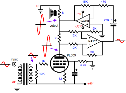
Mr. van Doorn claims that this current flow from the tube to the solid-state output stage forces the output stage to run in class A—and single-ended class-A operation no less. And he is right, as long as no loudspeaker with an impedance of less than 100 ohms is driven. Remember, when specifying class-A operation, one must also specify the load impedance and the peak voltage swings. With an 8-ohm load, a negative output voltage swing of only 2V (0.25W) is enough to turn off the top output device in the TDA7294 output stage, thereafter the amplifier runs in class-AB. Still, this seems a petty quibble when we are offered a high-wattage, affordable, hybrid, OTL power amplifier. Before we get to the severe part of the audio-autopsy, below is an illustration of the AC relationships within the amplifier.
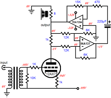
High-Level Audio-Autopsy We have already seen that 200mA does not a 50W single-ended amplifier make. Against 8-ohms, 200mA only equals 160mW; yes, milliwatts. In order to get 50W into an 8-ohm load, 3.5A of peak current and 28V of peak voltage are needed; 200mA is not much of a down payment. Now, if the tube's idle current is somehow exempt from the standard rules of amplifier classification, then why bother with a big heat-producing tube such as the PL509? Why not use a smaller tube and less idle current? In other words, if we are allowed to break rules, why no do so with wild abandon? Why not use a 2A3 or a 12B4 or a 6SN7 or a12AX7?
Sure, the 12AX7 only draws 1mA, but that 1mA must find a path through the TDA7294 output stage, no less than a PL509 does, so what is fundamentally different about this setup other than mere tube choice? (By the way, a 12AX7-based-hybrid-OTL amplifier just might sound much better than the pentode-based original, as triodes are much more linear than pentodes.) Wait a minute! Have I forgotten that vacuum tube does not just drive the solid-state power amplifier? Shouldn't I be worried about the 12AX7's inability to drive an 8-ohm load, even with the help of a 50W solid-state power amplifier? So, we finally arrive. I do not believe that Mr. van Doorn's OTL is an OTL. Yes, an output transformer is not used, but just about every solid-state works without an output transformer and yet no one feels compelled to bestow upon these power amplifiers the highly desired—by marketing departments if no one else—badge of “OTL.” The OTL insignia is usually reserved for power amplifier that use power tubes to drive loudspeakers without using a coupling transformer at the output. And while the PL509 does dissipate 20W at idle, the real question is How many of those 20 watts actually make into the loudspeaker? 20W? 10W? 5W? 1W? 1mW?
One test we could perform is to remove the INA137 differential line receiver and measure the voltage swing into the loudspeaker while the PL509 is driven to full output. What can we expect to see? The PL509 undergoes a current swing of 70mA at full output and I assume that the TDA7294 presents a low output impedance, say a damping factor of 100, which would imply an output impedance of 0.08 ohms. Now, 70mA against an output impedance of 0.08 ohms equals a peak voltage swing of 0.0056V, which in turn equals 2µW of power into 8 ohms. Yes, microwatts….If only they made a 200dB efficient loudspeaker. The big mistake we must avoid is to ascribe intentionality* to electrons. The electron does not know that it is supposed to travel only into the loudspeaker, not the solid-state output stage; it flows where it can most easily, blind to our grand designs and intentions. (No doubt that you have been told that in multi-gauge loudspeaker cable, the high frequencies travel through the thin wires and the lows travel through the fat wires, exclusively. Does this mean that if we hooked up the thin wires to the woofer and the fat wires to the tweeter that no sound would be forthcoming? And if the SPL should prove identical to the inverse, what the heck are cable guys talking about?) In other words, the solid-state power amplifier is doing all the hard work and the tube is only driving the solid-state amplifier, not the loudspeaker. Still not convinced? How about if we rearrange the topology so that the tube's current does not flow into the TDA7294's output stage, as shown below.
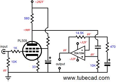
The power MOSFET's gate is quite isolated from its source, so all the current flowing through the tube will flow through the power MOSFET up to the 32V power supply rail, never seeing the loudspeaker along the way. Yet this variation will perform in an almost identical fashion to the original topology, as the same AC voltage relationships exist. (To make it closer still, a 470-ohm power resistor can be attached from the -95V power supply rail to the TDA7294's output, so the solid-state power amplifier will still experience the crossover-notch displacement. I left out this resistor from the schematic to make the topoology clearer.) So is the above amplifier an OTL? Or is it just a hybrid amplifier? Well, let us engage in some more topology alteration. The hybrid amplifier below uses the same two core components: the PL509 and the TDA7294, with the same operating points and voltage gains. Would this hybrid sound any different from the original? I doubt it. And if not, why bother with the original? There are much easier, simpler, cooler ways to build a good hybrid amplifier.
Thus, it seems that Mr. van Doorn has created a hybrid
audioXpress Editor Edward T. Dell deserves a big slap on the back, a free beer, and your subscription. Believe me, running a DIY audio magazine is about the least profitable way to expend your efforts and talents. Imagine going to the bank to ask for a new business loan and having to tell bank officer that you wish to create a DIY audio magazine… When the laughter dies away, so will have all your hope of creating the magazine. Why? DIY runs contrary to our modern consumerism-based culture, wherein we are supposed to buy, buy, buy, consume, consume, consume, discard, discard, discard… not create, not design, not build. Well, now that I am stirred up, I might as well go into full rant mode.
John Broskie 's Rant The consumer king paid too much, as he gave up more than just money: he gave up his sovereignty, as well. Now, the most the consumer king can aspire to is an exultant and impeccable consumption, a consumption as extravagant as his bank account allows and as correct as the experts, engineers and designers, vouchsafe. Not too long ago, 50 years ago let's say, the average audiophile reigned over his system, owning an understanding of the circuitry and the mechanics involved, building and designing much of it himself, selecting and choosing the fundamentals, triode or pentode, single-ended or push-pull, rather than just choosing the appearances: oak or walnut veneer, brown or black grill cloth. Today, solid-state audio equipment neither invites nor easily admits understanding. The brightest engineer cannot decipher the purpose of an unmarked IC. And it is unlikely that any one engineer fully understands a $100 CD player with its mechanical actions and its IC encapsulated digital-to-analog converters and digital filters. It took many engineers to design that CD player and it takes many engineers to understand it. In contrast, tube circuitry is fundamentally different. It is readily understandable; in years past, GIs and sailors learned in a few months how to understand and fix fairly complex tube equipment. In addition, tube circuitry is readily malleable: circuits can be altered, modified, and augmented, like the great American hotrod. Because it is understandable, because it admits modification, owner-built tube audio restores the lost sovereignty of the owner. Thus, the builder of tube gear is like the teenager who builds the hotrod he desires, believes in, and that expresses his vision. The poor rich kid, hobbled by too much money and by a fear of grease under his fingernails, can only hope to buy, but never really own such a hotrod. Continuing the car analogy, solid-state gear is like the near solid mass of wires, pipes, and sealed-metal parts under the hood of a new car. And just as no one can imagine modifying the aperture of the fuel injection jets in his Lexus, no one would want to de-solder the surface mount resistors and capacitors on the circuit boards to his CD player. Exit rant-mode.
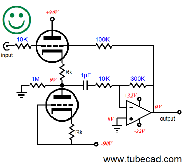
Putting the AI-kido into the gAInclone If you read the above rant, you will see how the power OpAmp fits in the same liberating box as tubes do, as the power OpAmp, because it is similarly simple, helps us regain our sovereignty over our stereos. Now, all we need to do is figure out how to best wed a gainclone to a tube-based frontend. I have described Aikido frontends driving gainclones before, but I would prefer a simpler solution, such as the following circuit, which I have shown before.
Such a hybrid amplifier offers some interesting features. First, the tube is calling the shots, as the feedback loop encompasses the solid-state power amplifier and the tube decides what needs fixing. Second, the two 90V rail voltages can easily be derived from a 44Vac, center-tapped secondary, which would also provide the two 32V power supply rails for the gainclone amplifier. Third, the tubes will add neither excessive distortion or noise, as the symmetrically-loaded cathode follower is linear and it nulls the opposing power-supply-rail noise at its output.
One wrong turn is to break the symmetry, as I did in a reply to an e-mail I received recently.
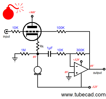
The reader had asked for my take on a tube-based gainclone amplifier and I thought that that less might be more. It wasn't.
The above schematic shows a misstep, as the constant-current source makes a poor substitute for the triode and cathode resistor, as I discovered after running a few SPICE simulations. The cathode-follower/constant-current-source version was much worse than the original version with two triodes. By the way, does anyone know of a power OpAmp that is unity-gain stable or low-gain stable?
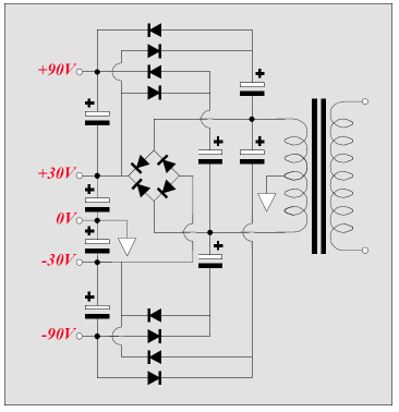
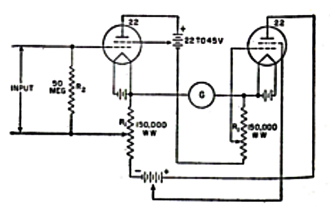
Circlotron Lie Detector
//JRB
|
Now accepting
E-mail from GlassWare Customers And
High-quality, double-sided, extra thick, 2-oz traces, plated-through holes, dual sets of resistor pads and pads for two coupling capacitors. Stereo and mono, octal and 9-pin printed circuit boards available.
Designed by John Broskie & Made in USA Aikido PCBs for as little as $24 http://glass-ware.stores.yahoo.net/
The Tube CAD Journal's first companion program, TCJ Filter Design lets you design a filter or crossover (passive, OpAmp or tube) without having to check out thick textbooks from the library and without having to breakout the scientific calculator. This program's goal is to provide a quick and easy display not only of the frequency response, but also of the resistor and capacitor values for a passive and active filters and crossovers. TCJ Filter Design is easy to use, but not lightweight, holding over 60 different filter topologies and up to four filter alignments: While the program's main concern is active filters, solid-state and tube, it also does passive filters. In fact, it can be used to calculate passive crossovers for use with speakers by entering 8 ohms as the terminating resistance. Click on the image below to see the full screen capture.
Tube crossovers are a major part of this program; both buffered and un-buffered tube based filters along with mono-polar and bipolar power supply topologies are covered. Available on a CD-ROM and a downloadable version (4 Megabytes). Download or CD ROM
|
|||


| www.tubecad.com Copyright © 1999-2008 GlassWare All Rights Reserved |