| John Broskie's Guide to Tube Circuit Analysis & Design |
|
1 January 2017 Post 367 Happy New Year
2017! Two years to go the Tube CAD Journal's twentieth anniversary. It's amazing how time flies—even when not having fun. Not having fun? We are having our basement finished, so my office is now in our dining room. Ouch! Soon enough, however, I be back downstairs and my library and tools will be restored unto me. I haven't come close to exhausting the topic of single-ended amplifiers; nonetheless, a brief interlude can only assist us on this long trip.
SRPP Redemption
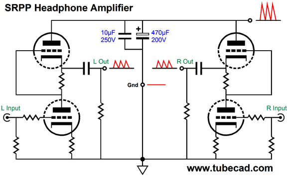
I encountered the SRPP, back in the 1970, while I was in college. An SRPP-based headphone amplifier became my first tube-audio project (I owned a Dynaco ST-70 in high school, but I left it stock). Here is a quote from post 171.
I had used a 6DJ8 and a polypropylene coupling capacitor, which was rare back then and I was in love, as the sound was lovely. The bass response, however, was lacking, if not altogether lacking; nonetheless, the clarity was breathtaking. (I ended up augmenting the bass with my huge, massive subwoofer.) My party trick back then was not to tell friends that I owned a subwoofer—not that more than one on ten knew what a subwoofer was. As the friend listened to headphones and subwoofer, his ears were tickled by sweet mids and his stomach was punched by deep, subsonic shocks. As soon as he motioned to remove the headphones, I muted the sound, so he remained convinced that all the sound he heard emanated from the feather-weight headphones.
All was not bliss and rainbows, as the HD414's high impedance made the SRPP's poor PSRR even more noticeable. Thus was born my lifelong interest in high-voltage power supplies and PSRR enhancements. Of course, if the power supply was truly noise-free, the SRPP's poor PSRR didn't matter. If I owned a time machine, however, I would go back to 1978 and, other than buy as many WE 300Bs as I could, I would show myself a simple technique for greatly improved headphone playback with the SRPP circuit. But first, let's backtrack and review what went wrong with a stock SRPP headphone amplifier.
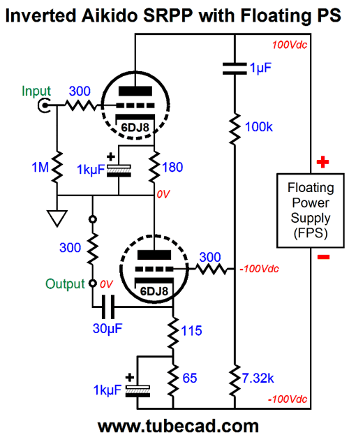
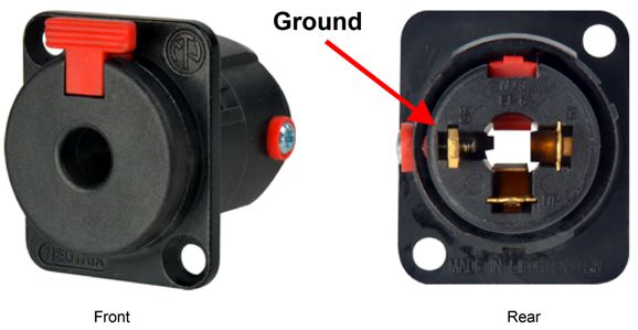
With a 1M external load impedance, the SRPP's PSRR comes in at about -6dB, which means that about 50% of the power-supply noise leaks through the output, as shown above. The lower the load impedance, the better the PSRR, but then the less power a tube-based SRPP can deliver. One solution is to use a well-regulated power supply. This is the brute-force solution. My solution can be used with a well-regulated power supply, but does not require it. Rather than try to fight the power-supply noise, we accept that some power-supply noise will, like the poor, always be with us. We realize that if the "ground" connection were equally contaminated with power-supply noise as the SRPP's output, the headphone driver would see no differential signal across its leads, so the driver would have to ignore the power-supply noise.
In other words, no direct connection to ground is made; instead, we give the headphone "ground" terminal a faux ground, one that holds just as much power-supply noise as the two outputs do. Mind you, regulators that seem noise free at dile, can produce signal induced weirdness, as they are required to pass a quickly varying amount of current. This Aikido faux ground technique even works with this latter regulator failing, as it will present the same portion of weirdness at the faux ground as is present at the output.
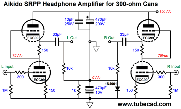
Here is a design example, which assumes that 300-ohm headphones, such as those made by Sennheiser are used.
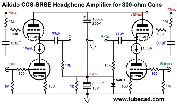
The top 470µF capacitor is a high-voltage electrolytic type, while the bottom 470µF capacitor is a low-voltage non-polarized capacitor, which is shunted by a 1k resistor and diode. The resistor ensures that no DC offset occurs at idle, while the diode prevents overcharging of the bottom capacitor at startup. If the B+ ripple peak voltage exceeds 1.2V, this diode will end up clipping the power-supply noise, which will worsen the potential PSRR enhancement. Mind you, 1200 mV of peak ripple is a lot of ripple. Note that the top 470µF capacitor is bypassed by a 10µF film capacitor, which brings the top capacitance up to 480µF. This slightly larger capacitance helps the virtual ground present the same amount of ripple as the outputs hold, as all SRPP circuits that hold matching cathode and current-sense resistor values, and which do not bypass the cathode resistor, leak a tad more than 50% of the power-supply noise out their outputs when unloaded. What if a different tube were used, say a 5687 or 6H30? Not much changes, other than the optimal current-sense resistor value. On the other hand, if we switch the topology to a mu follower (SRSE), then the top and bottom capacitor ratio will need changing. The ratio is easy to find: just make the bottom capacitor mu times bigger in value than the top capacitor. For example, an ECC99 offers a mu of 22, so the 100µF top capacitor must find a 2.2kµF partner below.
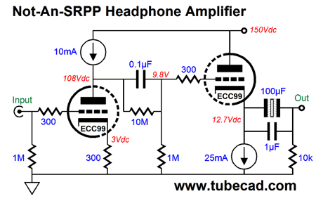
Since we have left push-pull operation behind, we only get the idle current as the peak output current into the load. One solution is to break the circuit into two horizontal stages.
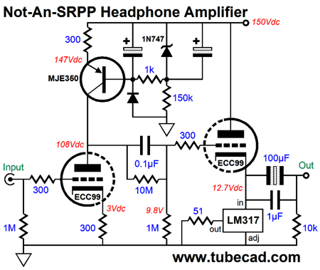
The same tube is used, the ECC99, but as we have effectively doubled the B+ voltage, we can run a much more heavy idle current for the output triode, 25mA in this example. The 10M resistor allows some of the first stage's plate voltage to bleed across the 0.1µF coupling capacitor. I get a few e-mails that complain that I too often use a constant-current source symbol, rather than the actual constant-current source schematic, which is needed to build the circuit. In deference to those who need to see a full schematic, here is one possibility.
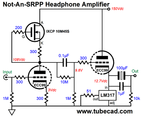
Too complicated? Well, the next possibility is simpler.
The LM317 is used in both designs and it works well as a constant-current source. Does this inclusion of two constant-current sources ensure a supremely high PSRR? No. We can, however, apply the same trick of creating a virtual ground for the headphones.
The same ratio of 1:22 is used, as the same ECC99 is used. What if we use an output transformer instead? The transformer primary's DCR can be used to bias the output triode and multiple taps on the secondary would allow us to drive both high and low impedance headphones.
But the same problem of some of the power-supply noise leaking out remains. The workaround would be to terminate the primary into a two-capacitor voltage divider.
Note the 30-ohm primary DCR, which combined with the 100-ohm resistor bias the output tube. Also note the same mu:1 ratio of the capacitors. If the transformer does not hold an air-gap, the following variation should be used.
The same mu:1 ratio of the capacitors is used, but the capacitors are much smaller in value. Why? We do not need to overwhelm a 100-ohm resistor's resistance, so we can use values appropriate to the secondary impedance, which in this example is assumed to be at least 600 ohms. The formula is easy enough: C = 159155/R/F where C is capacitance in µF; R, load resistance; and F, the -3dB low-frequency cutoff. For example, with an F of 20Hz and an R of 600 ohms, C should equal 13.3µF, making 22µF perfectly adequate.
Next Time: Vertical Versus Horizontal
//JRB
If you have been reading my posts, you know that my lifetime goal is reaching post number one thousand. I have 633 more to go. My second goal is to gather 1,000 patrons. I have 976 patrons to go. If you enjoyed reading this post from me, then you might consider becoming one of my patrons at Patreon.com.
Next Time
User Guides for GlassWare Software
For those of you who still have old computers running Windows XP (32-bit) or any other Windows 32-bit OS, I have setup the download availability of my old old standards: Tube CAD, SE Amp CAD, and Audio Gadgets. The downloads are at the GlassWare-Yahoo store and the price is only $9.95 for each program. http://glass-ware.stores.yahoo.net/adsoffromgla.html So many have asked that I had to do it. WARNING: THESE THREE PROGRAMS WILL NOT RUN UNDER VISTA 64-Bit or WINDOWS 7 & 8 or any other 64-bit OS. I do plan on remaking all of these programs into 64-bit versions, but it will be a huge ordeal, as programming requires vast chunks of noise-free time, something very rare with children running about. Ideally, I would love to come out with versions that run on iPads and Android-OS tablets.
//JRB
|
|
Kit User Guide PDFs
Only $12.95 TCJ My-Stock DB
Version 2 Improvements *User definable Download for www.glass-ware.com |
||


| www.tubecad.com Copyright © 1999-2017 GlassWare All Rights Reserved |