| John Broskie's Guide to Tube Circuit Analysis & Design |
23 July 2019 Post Number 472
Errata
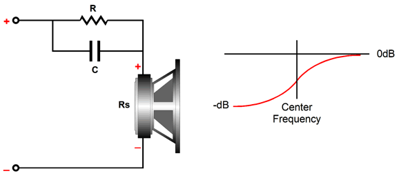
Now, we move on to those formulas for a highs-tilting control circuit.
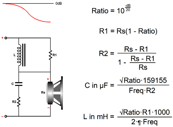
While on the topic of frequency tilting, I should mention that my circuits are more complicated than the standard circuits. For example, here is easy bass-tilt circuit.
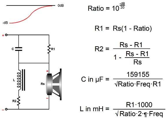
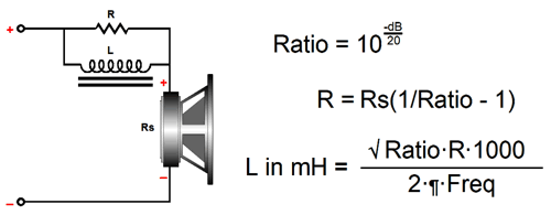
Only two components are needed, a resistor and an inductor. At low DC and low frequencies, the inductor shorts out the resistor, allowing the loudspeaker driver to see the full amplifier output voltage. At high frequencies, the inductor's impedance is so high that effectively only the resistor remains in the circuit and the driver sees an attenuated amplifier output voltage. In other words, we have imposed a bass boost by attenuating the high frequencies. Because this circuit is passive, we incur an insertion loss at high frequencies, so the driving amplifier must offer sufficient headroom to make up for the loss. Here is the highs-boosting version.
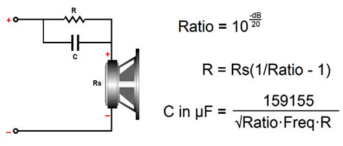
Okay, since the easy versions requires fewer parts, why did I come up with my more complicated versions? The first answer is found in impedance plots. My versions results in a flat impedance equal to the driver's impedance. The easy versions don't yield a flat impedance, as the impedance only equals the driver's when the series resistor is shunted by either the inductor or the capacitor, but then rises once either the inductor or capacitor impedance rises, creating a summing of driver's impedance and the series resistor value. Obviously, the greater the boost, the less flat the impedance plot will be. In other words, if the boost is modest, we can probably get away with the easy version. On the other hand, if the easy version is used with a single driver in a multi-way speaker, then the non-flat impedance will screw up the passive crossover, whereas my more complicated version won't, as the flat impedance is passive crossover friendly. By the way, I should point out that the standard formulas for the easy tilt circuits are not optimal, as they fail to place the transition frequency at the target center frequency. Here is the correct procedure for the easy bass boost.
Next, the high-boost version of the easy circuit.
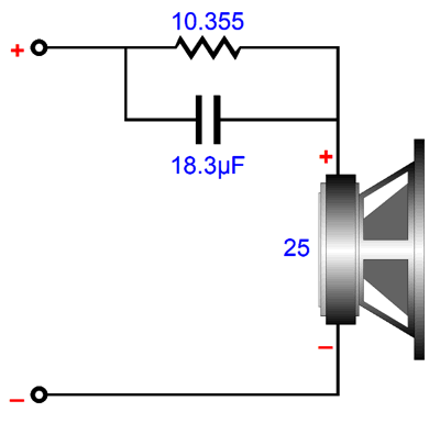
The key part in both circuits is the square root of the attenuation ratio. Here is an example with a target transition frequency of 1kHz and an 25-ohm driver impedance and a boost at high frequencies of +3dB.
The standard formula for the capacitor value, C = 1/(2piFrequencyR), results in too low a value, so the center frequency occurs at 1189Hz, not 1kHz. By the way, we might end up with an unintended bass boost with this simple circuit, as the series resistor will greatly increase the drivers Qes, which in turn will increase the Qts, undoing the bass damping. Of course, some will view this as just an added bonus.
The second reason that I came up with my more complicated tilt circuits was that the easy versions simply do not work with current-output amplifiers, whereas mine do. Think about it: when an amplifier puts out fixed current, rather than fixed voltage, the loudspeaker driver does not see the easy tilt circuits' capacitors, inductors, or resistors, so no boost obtains. Now consider this: most tube-based amplifiers straddle some position between voltage-output and current-output amplifiers, neither belonging completely to one group nor another due to their relatively high output impedance.
If you enjoyed reading this post from me, then you might consider joining my other patrons at Patreon.com (The patrons I have, the more time I can devote to creating these posts.)
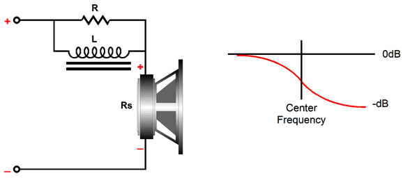
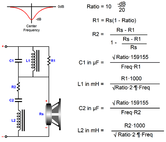
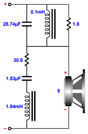
Bump and Dip Circuits To reduce a frequency peak, we need a frequency dip at the same frequency. Effectively, we do not incur a true insertion loss, as only the driver's over exuberance at some frequency experiences the loss. In other words, if the speaker's peak SPL with 100W of amplifier power was 100dB, then the same maximum of 100dB obtains with the frequency-dip circuit, but flatter.
My version requires twice as many parts over the easy version, but it does ensure a flat impedance plot and it works with current-output amplifiers. Once again, the key variable is the square root of the attenuation ratio. Here is an example with a target transition frequency of 3 kHz and an 8-ohm driver impedance and a -2dB notch.
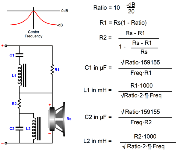
In contrast, since here are no free lunches, achieving a frequency bump will cost us an insertion loss.
Although the topology is different from the frequency dip version, the math remains the same, interestingly enough. My design example is a -4dB bump at 1kHz with a 25-ohm driver. I choose these values to work with my own Audioquest Blackhawk headphones, as they produce a complementary dip at 1kHz. (In fact, the dip might be even greater, but I used a digital equalizer and found that the +4dB sounded best to me.)
Note that many of the values are close to standard values. For example, 9.2 ohms for R1 could be replaced with a 9.1 ohms resistor (or a 14-ohm I parallel with a 27-ohm resistor); the 42.7-ohm resistor, with a 43-ohm resistor; the 2.958µF capacitor, with a 3µF; and the 13.7µF capacitor, with a 13µF and 0.68µF capacitor in parallel. The two inductors could be made from unwinding 2mH and 9mH coils, with the aid of an accurate LCR meter, until the exact values are hit. An important point to remember is that the inductor must be perpendicular to each other to avoid inductive coupling. All 12 parts (do not forget stereo) will require a fairly large enclosure. In other words, this would not prove suitable to use with a personal audio product (PAD) and headphones and walking the dog, unless you plan on pulling a wagon behind you. On the other hand, if you do not mind the wagon, you might as well add a tube-based headphone amplifier and a DC-to-AC converter and boat battery. By the way, I can imagine a new audio product—namely, either a passive tilt control or frequency bump or dip circuit for high-end headphones. Housed in a fancy enough box and filled with Duelund or Mundorf and inductors along with fancy wire and resistors, this accessory could easily cost several times as much as the headphones, say between $4,000 to $20,000, which would vouchsafe its high-end credentials. For example, a 2mH, Duelund Coherent Audio, PIO cast copper air core 12awg inductor can be bought for only a little over one thousand dollars, which may not include the armed-delivery service. Surely, you are using headphone cables that cost more than the headphones? Who knows: perhaps such an expensive box might actually sound better than the cheaper alternative filled with reasonably priced polypropylene capacitors and typical loudspeaker inductors. But even if it didn't or, worse, it sounded inferior, we would still retain the bragging rights, which only increase with the price.
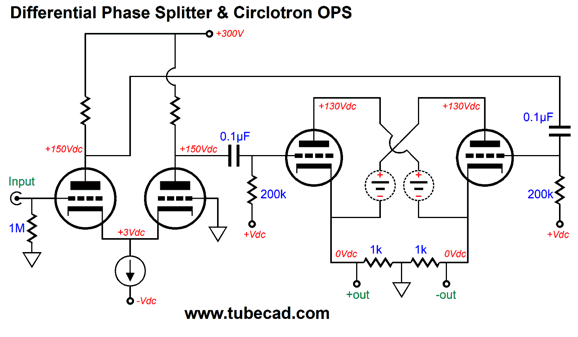
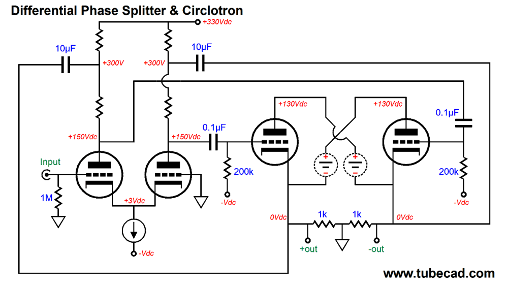
Differential Phase Splitter and Circlotron
On the other hand, if we wish to get fancy, we can return the OTL's output to the phase splitter, thereby creating two local negative feedback loops.
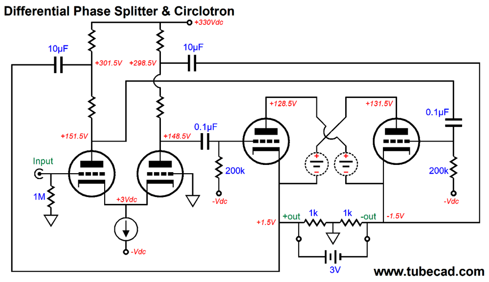
Note that the output stage uses two floating power supplies. The two extra capacitors relay the output to the phase splitter in an anti-phase fashion, which reduces both the resulting gain and output impedance. To see how the negative feedback works, imagine tapping the two outputs with a battery. The resulting pulses, both positive and negative, would end up cross-coupling with the output tubes' grids, causing the output tubes to buck the imposed voltage pulses.
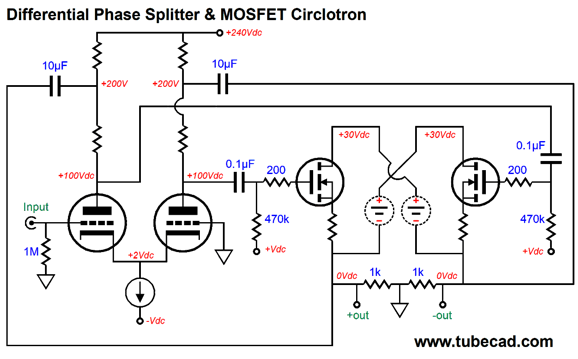
We could apply the same topology to a tube-MOSFET hybrid circlotron amplifier.
Since the MOSFET provide so much more transconductance than the output tubes, we can get away with far lower B+ voltage for both the differential phase splitter and the circlotron output stage. In fact, where the all-tube version would require an additional input stage to deliver need signal gain, the hybrid version might get away with just one tube per channel, especially if the signal source offered a pair of balanced output signals.
Music Recommendation: Stravinsky's Symphony of Psalms The story about its creation that I remember is far better than what Wikipedia delivers. I remember that in 1930 Stravinsky's publisher, Serge Koussevitzky, told Stravinsky something along the lines of, "Damn it, Igor, do you think you can write something a bit more old fashion, so we can sell more sheet music?" The three-movement symphony was commissioned by Koussevitzky to celebrate the Boston Symphony Orchestra's 50th anniversary. Although the work is often called neo-classical, it doesn't fit well within this label, as it is far too emotionally charged. It is well represented in recordings by many great conductors, but none can match the excitement produced at a live performance. (In fact, this seems to hold true for most pieces that hold large choirs, such as Mozart's Requiem Mass and Carl Orff's cantata Carmina Burana, either of which heard live pale the best recordings.) I decided to give Tidal a search and I discovered a new recording (well, 2007) that reawaken my love for the piece, with Karl-Friedrich Beringer conducting the Windsbacher Knabenchor choir and the Berlin Deutsches Symphonie-Orchester. What struck me immediately was—I am somewhat embarrassed to admit—the intense bass. Not that it was Sir Georg Solti and the Chicago Symphony Orchestra Beethoven's 9th bass-heavy, but you will hear the big bass notes instantly. Although Stravinsky's aim was to establish equality between orchestra and choir, it seems that we have to choose between the two in most recordings of this symphony. If you rather hear the choir more clearly, try Daniel Barenboim's effort with the Orchestra of Paris.
//JRB
User Guides for GlassWare Software
For those of you who still have old computers running Windows XP (32-bit) or any other Windows 32-bit OS, I have setup the download availability of my old old standards: Tube CAD, SE Amp CAD, and Audio Gadgets. The downloads are at the GlassWare-Yahoo store and the price is only $9.95 for each program. http://glass-ware.stores.yahoo.net/adsoffromgla.html So many have asked that I had to do it. WARNING: THESE THREE PROGRAMS WILL NOT RUN UNDER VISTA 64-Bit or WINDOWS 7 & 8 or any other 64-bit OS. I do plan on remaking all of these programs into 64-bit versions, but it will be a huge ordeal, as programming requires vast chunks of noise-free time, something very rare with children running about. Ideally, I would love to come out with versions that run on iPads and Android-OS tablets. //JRB |
John Gives
Special Thanks to the Special 86
I am truly stunned and appreciative of their support. In addition I want to thank the following patrons:
All of your support makes a big difference. I would love to arrive at the point where creating my posts was my top priority of the day, not something that I have to steal time from other obligations to do. The more support I get, the higher up these posts move up in deserving attention.
If you have been reading my posts, you know that my lifetime goal is reaching post number one thousand. I have 531 more to go. My second goal is to gather 1,000 patrons. I have 912 patrons to go. Help me get there.
Support the Tube CAD Journal & get an extremely powerful push-pull tube-amplifier simulator for TCJ Push-Pull Calculator
TCJ PPC Version 2 Improvements Rebuilt simulation engine *User definable
Download or CD ROM For more information, please visit our Web site : To purchase, please visit our Yahoo Store: |
|||


| www.tubecad.com Copyright © 1999-2019 GlassWare All Rights Reserved |