| John Broskie's Guide to Tube Circuit Analysis & Design |
09 December 2008
Power-Booster Amplifiers
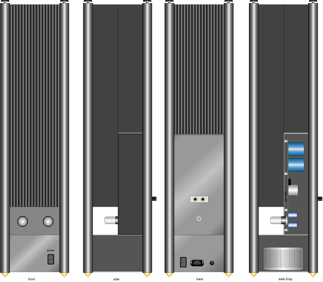
Or would it be? Yes, I know that the solid-state amplifier is in series with the small tube amplifier and that the tube amplifier will only drive the solid-state amplifier, not the loudspeakers. And I acknowledge that this scheme stinks of the notion that tubes make nice distortion, which I most wholeheartedly reject. So why bother with this approach to better sound? First, few will be surprised by my pronouncing my fundamental intellectual interest over any practical application; this is the Tube CAD Journal, not Practical-Tube-Hi-Fi.com, after all. I like tackling heavy ideas the same way a weight lifter enjoys lifting steel weights. For example, the question, How long could a man survive in a vacuum? I find quite intriguing, although I have no interest in discovering the answer firsthand. So too, I wonder what such a power-booster amplifier would look like and whether it would function radically differently from a standard solid-state power amplifier and if the beefy power-booster amplifier need be exclusively a solid-state affair or can tubes be used instead. One high-end audio power-booster amplifier already exists in the Musical Fidelity 550K power-booster:
Interesting. My favorite bit is the use of the word “doddle,” which as everyone knows is: Noun (Brit, Austral & NZ informal) something easily accomplished: the test turned out to be a doddle [Origin Unknown]. This handsome 550K power-booster amplifier reminds me of my long-held desire to build a power amplifier qua loudspeaker stand.
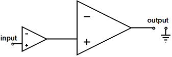
I know very little about the MF 550K’s circuitry and the best description of its functioning I found in the following PDF link. The 550K’s input impedance is a low 50 ohms (low for a power amplifier, but high for a loudspeaker replacement). It uses a differential output stage to maximize the output voltage swing. It offers a voltage step up of about 3.16 (the square root of 10). And its output impedance is extremely low. The 550K also offers a line-level, high-impedance input, for those who just need a powerful amplifier. The first question that comes to mind is, Why a 50-ohm load? I believe this is a nod to all us tube fanciers, as a transformer-coupled amplifier requires a somewhat low load impedance, as inductive coupling is the exact opposite of capacitive coupling. For example, the lower the load resistance, the less inductance needed; the higher the load impedance, the less the capacitance needed. In other words, if the 550K had presented only a 47K input impedance, tube power amplifiers (the transformer-coupled type) would experience gross bass attenuation. On the other hand, the 50-ohm load impedance is high enough to keep both solid-state and tube amplifier operating over a wider class-A range, because of the less steep loadline. A compromise, in other words. The next question is Why a gain of about 3.16? The 550k aims to increase the input amplifier’s output by tenfold, which means that the both the output voltage and current must be increased by the square root of 10, i.e. 3.1627. For example, 50W into 8 ohms requires 28.28Vpk and 500W into 8 ohms requires 89.44Vpk, which is 3.16 times greater than 28.28V. This amount of voltage gain also sets the required input voltage to realize the full 500W of output power, about 28V. In other words, if you use a tiny 2.5W single-ended amplifier, the 550K will only put out 25W of power, although it is capable of twenty times more output power. Returning to my original three questions: What would such a power-booster amplifier look like? Can it function in a radically different fashion from a standard solid-state power amplifier? And, must the beefy power-booster amplifier be exclusively a solid-state affair or can tubes be used instead? Let’s start with the first question. Almost all solid-state power amplifiers consist of three stages, an input stage, a driver (VAS) stage, and an output stage. Would a power-booster amplifier need an input stage, as the existing power amplifier will already provide a good bit of gain? And what about the driver stage? Cannot the existing small power amplifier drive the power-booster amplifier’s output stage directly?
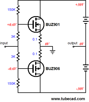
The above buffer circuit looks promising, but the problem lies in its offering no voltage gain, so our 2.5W power amplifier will still put out 2.5W after passing through the power-booster amplifier. This is the problem that Moskido power amplifier users are finding, as the Aikido gain stage can only offer a gain equal to about half of the mu of the input tube used, which in the case of the best-sounding 6SN7, is only 20, yielding a final voltage gain of only 10. In other words, it looks like at least two stages are needed. Or are they? Let’s do some heavy mental power lifting. The two power transistors, in the schematic shown above, use all their available transconductance to deliver current gain, not voltage gain. (By the way, the above circuit might work beautifully for someone who owns a 2.5W flea-power amplifier and 1-ohm ribbon loudspeakers, as the small power amplifier’s 6Vpk swing into a 1-ohm load creates 18W of dissipation. Cool. A 20W amplifier’s output voltage would develop 160W!) What if we use some of the output device’s transconductance to provide a bit of voltage gain at the expense of losing some of the low output impedance? A wonderful trick, but how do we pull it off? Long-time readers of the Tube CAD Journal will remember my early blog posts on simple power amplifiers.
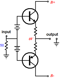
In the simple-PP-amplifier post, I outlined the following simple power amplifier topology with just two output devices and voltage gain.
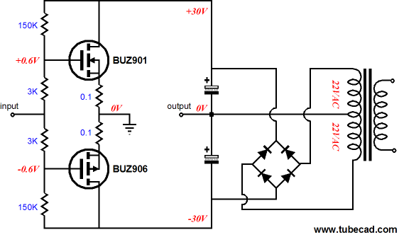
The batteries are no doubt confusing to many, but they serve to show how the power supply must be free to follow the output signal. In an actual amplifier, the following setup is more likely. In other words, each channel must have its own power transformer winding and rectifier circuit.
Sagaris Amplifier
The Sagaris Amplifier has arrived. Sagaris is an Ancient Greek word for the doubled-headed battle axe used by the Ancient Persians. (I wanted to the call this topology the Labrys Amplifier, but I did not want to get anymore sexually themed spam than I presently do, although I am sure that any such new spam would prove a welcome relief from the super-sizing-, super-stiffening-spam I now receive.)
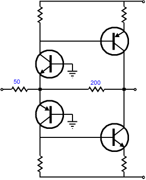
The Sagaris Amplifier uses two DC feedback loops to keep the output centered at 0V and an AC feedback loop to reduce the gain and lower the output impedance and distortion. Of course, different output devices could be used or several output devices could be placed in parallel. The two potentiometers help with amplifier housekeeping, such as setting the idle current and the output offset voltage. With the present devices and rail voltages, about 50W of output into 8 ohms is possible. Here is an alternative topology, which uses two stages.
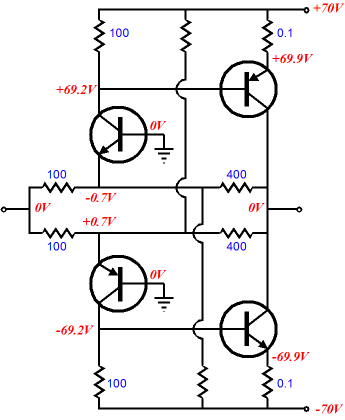
As configured, such an amplifier could not work in reality, as the input stage transistors are not correctly biased, but adding two resistors and separating the feedback loop into two parallel feedback loops does make something closer to usable.
Actually, the more I look at the schematic, the more I would prefer to use MOSFETs as output devices. The grounded-base amplifier will not provide any voltage gain at its collector with the present resistor values, but with a larger collector resistor, it could. I could go on with many other possible solid-state power-booster amplifier designs, but what I want to end with is an all-tube power-booster amplifier.
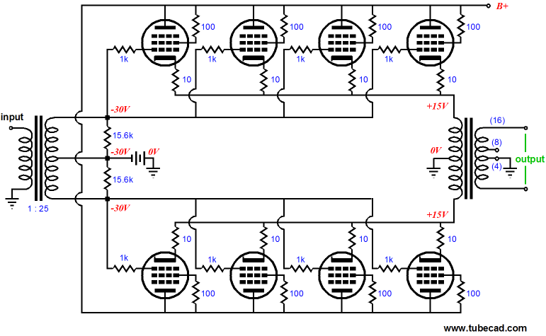
The above amplifier uses a 5k/10-20W output transformer to act as a phase splitter and to provide a huge voltage gain. We need all the voltage gain we can squeeze out, as the output stage is configured as a push-pull cathode follower. The eight output tubes use both cathode- and grid-bias to set the idle current. The two 15.6k resistors are reflected to the primary as 50-ohm load, as the transformer's winding ratio was 1:25, which implies an impedance ratio of 625 (625 x 8 = 5,000). If EL34s or KT88/6550s are used, a B+ of about 400V to 500V will be needed. On the other hand, if a low-voltage/high-current sweep tube, such as the EL509 or 6LF7, is used, the B+ voltage can be lowered to a mere +170V (6AS7s are another good choice). I am tempted to stop right here, as what follows could be lethally dangerous. Since this power-booster amplifier uses an input and output transformer, the active circuitry is nested in between, making no DC contact with either the input or output. In other words, this power-booster amplifier might be a perfect candidate for using the otherwise dangerous rectified wall voltage trick, wherein no power transformer is used; instead, the raw wall voltage is rectified and used as the B+ voltage. What makes using the wall voltage directly instead of a power transformer dangerous is the danger of the input or output transformers developing a short between windings. Fuses help, but I would still be nervous, particularly if a toroidal transformer were used, as the primary and secondary are in intimate contact. On the other hand, transformers that use separate wire bobbins, such as many C-core and R-core transformer do, would prove much safer. Even if we forgo a B+ power transformer, a power transformer will still be needed for the negative-bias voltage power supply and the heaters. (Unless, twenty 6.3V tubes were used, ten per channel, so that the 20 heaters elements could be placed in series like a Christmas tree light string. Of course, if you live in a 230Vac country, this trick will not work. In fact, I would be afraid of trying it myself, as I would prefer to give each bank of output tubes its own independent heater winding, as the cathodes will move up and down hundreds volts. By the way, if thirty tubes were used, the amplifier could be named a Triakontoros.) One last point to be made is that the output transformer uses the entire secondary to drive the loudspeaker; we need to use a low-winding-ratio output transformer, because of the low impedance presented by the many parallel output tubes. In addition, the output tubes could be wired as pentodes or triodes or even in an ultra-linear arrangement, as I described in blog 139.
Next Time
// JRB
|
Kit User Guide PDFs
E-mail from GlassWare Customers
And
High-quality, double-sided, extra thick, 2-oz traces, plated-through holes, dual sets of resistor pads and pads for two coupling capacitors. Stereo and mono, octal and 9-pin printed circuit boards available.  Aikido PCBs for as little as $24 http://glass-ware.stores.yahoo.net/
Support the Tube CAD Journal & get an extremely powerful push-pull tube-amplifier simulator for TCJ Push-Pull Calculator
TCJ PPC Version 2 Improvements Rebuilt simulation engine *User definable
Download or CD ROM For more information, please visit our Web site : To purchase, please visit our Yahoo Store:
|
|||


| www.tubecad.com Copyright © 1999-2008 GlassWare All Rights Reserved |