| John Broskie's Guide to Tube Circuit Analysis & Design |
|
03 June 2007
“Shunt regulators! Not again!” Or, “Cool, more shunt-regulator information! It’s been a long time coming.” My guess is that most TCJ readers divide into one of these two opinions. Or maybe I am way off here—maybe I am falling into the excluded-middle* fallacy. For example, Carl Jung commandeered the word “introvert” and he coined the word “extrovert.” We all love using these two terms and we love seeing ourselves as being one or the either, but we forget that Jung also coined the word “ambivert” to describe other 85% of the population, most of us being neither exceptionally extroverted nor introverted. So it might be that 85% of regular TCJ readers are neither smitten with shunt regulators nor bored to death with the topic. (Of course, just as ambiversion escapes our awareness, a neutral stance does not compel the writing of angry or laudatory letters to the editor, so the impression left is that the other predisposed 15% of readers indicate 100% of all the readers. And since I am prejudiced in favor of the shunt regulator, it is easy for me to not see the non-predisposed 85%.) Two events force me to take up the subject of shunt regulators again. The first is that audioXpress magazine has just discovered the shunt regulator; or rather, they have re-discovered it, as the title to the article by Ed Simon in the June 2007 issue is “Shunt Regulator: The Almost Forgotten Circuit.” The article is interesting, although not especially well written. Wait a minute, isn’t my describing his piece as not being well written an example of the zener calling the carbon-composition resistor noisy? Well, yes and no. Yes, as my blog entries are a bit rough, being only quick first drafts, not polished prose pieces; and no, most certainly no, as my blog entries are not articles published in a glossy magazine, which should hold to a higher standard of writing (if not my own wild inventiveness and good-natured surliness). For example, here is Mr. Simon’s first sentence:
Or is it "most sound systems," not most of you? I am surprised that Edward Dell, audioXpress’s editor, didn’t rewrite that sentence to read:
or Or, what might prove best is to fuse the first and second sentences together (the second sentence explains how a sound system’s power supply must convert AC to DC voltage),
echoing Rousseau’s famous quip, “Man is born free and everywhere he is in chains.” Of course, not every reader will catch the allusion, but the 20% that do will crack a small smile, something that the original first sentence could never induce. (Or you might be like my wife and prefer Mr. Simon's original sentence?!)
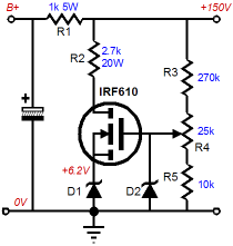
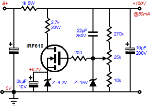
Circuit Number 1
In the schematic above, we see a high-voltage MOSFET doing the shunting and a zener providing the reference voltage (the second zener D2 is a safety device that only conducts when something has gone wrong). Resistors R3, R4, R5 define a voltage divider with an adjustable division point, which completes a feedback loop, bringing the error signal to the MOSFET’s gate. Resistor R2 serves to unload the MOSFET’s dissipation by displacing much of the high voltage on the MOSFET’s drain. Not a bad circuit. But it is more interesting for what is missing than for what has been added. For example, the 6.2V zener cries out for a large-valued bypass capacitor, say a 2kµF, 10V electrolytic.
This bypass capacitor would help shunt away zener noise and slow the high-voltage ramp-up at startup, as this capacitor slowly charges up to 6.2V, the B+ voltage must also slowly climb to 150V. A second missing capacitor is the output capacitor that bypasses the shunt regulator’s output.
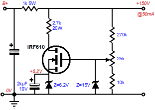
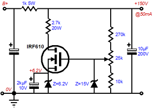
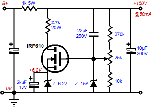
My experience with shunt regulators has been that without some capacitance on the output, expect some oscillation. The final missing capacitor is the feedback capacitor that overrides the voltage divider’s DC voltage division by relaying 100% of the AC errors on the output to the shunt regulator’s inverting input.
The last missing component is the gate-stopper resistor. MOSFETs, like triodes, present an extraordinarily-high input impedance, which can easily spell high-frequency oscillation grief. Adding a 200-ohm resistor can save a MOSFET from self-destruction, with virtually no liabilities.
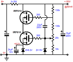
The above schematic fills in all the missing components. (The odd thing about Mr. Simon’s shunt regulator is that the missing gate-stopper resistor and shunting output capacitor are present in his second shunt regulator. In fact, I am not altogether sure that he was offering his first shunt regulator as final design or just as an illustration of some key features, before moving on to his secondary and, as he labels it, “Final Circuit.”) So, are we done modifying his shunt regulator? No, as I don’t much like the 2.7k, 20W power resistor, as it would be both hard to find, large, and expensive. Besides, is it really necessary, as the IRF610 is a 36W device? The worst-case dissipation (no load) is still under 10W for the 36W MOSFET (I know that solid-state devices are wimpy, but not that wimpy). Furthermore, shouldn’t we be more worried about the MOSFET’s low 200V drain-to-source breakdown voltage? IRF610s cost less than a dollar, which is certainly compelling (particularly compared to the price of a 300B), but for less than two dollars, we can buy the IRF710, a 400V, 36W device. I would gladly pay twice as much for twice the piece of mind. Or we could use two IRF610s in cascode, thereby doubling the 200V limit and halving the dissipation, as shown below.
Circuit Number 2
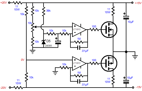
Well, is it going to be thumbs up or thumbs down? How about thumbs sideways? Once again, we have to avoid the dreaded excluded-middle fallacy trap. In addition, what about both up and down? (Strictly speaking, the word “ambivalence” does not mean indifferent or indecision or irresolution, but the paradoxical coexistence of opposing attitudes or feelings, such as love and hate, joy and sorrow, admiration and revulsion.) No, I am not tergiversating (waffling), I am just experiencing ambivalent emotions as I evaluate his circuit. First of all, anyone who comes up with an original circuit deserves a free beer and a pat on the back. Second, I am somewhat tickled to see a circuit so purposely inefficient, filled as it is with hot 10W resistors, holding two cascading stages of regulation, delivering only half of the initial DC power-supply voltage. Third, I wonder why better series regulators were not used, such as LM317LM337s or LT1085LT1185s. Fourth, I don’t see why a voltage reference is needed, considering that the series regulators already provide fixed output voltages, serving as two voltage references in themselves. Fifth, and lastly, I do get why each OpAmp holds two feedback loops, one from the regulator’s output and one from the OpAmp’s output, limiting the OpAmp’s closed-loop gain to 100. So how would I design a low-voltage, bipolar, series-shunt regulated power supply? I would start with quality series regulators and then I would greatly simplify the shunt regulators.
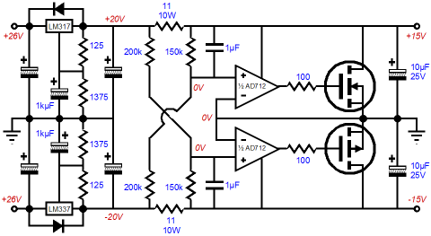
In the above schematic, the two fixed, series voltage regulators have been replaced by two adjustable series regulators. These regulators provide excellent noise rejection and a slow turn-on, as the 1kµF bypass capacitors must be charged through the 125-ohm resistors. (Since the 125-ohm resistor sees a constant 1.25V across its leads, a constant 10mA must flow through the resistor, which will charge a 1kµF capacitor up to 13.75V after 1.375 seconds, which may not seem that long, but in electronic terms, it is a long, long time compared with the 10 milliseconds or so that a fixed regulator can take to come up to its fixed voltage.) Now let’s look at the series regulators’ output voltages as voltage reference for the two shunt regulators. Each OpAmp and its corresponding MOSFET define a single-ended amplifier, an inverting amplifier, so the OpAmp’s inputs are effectively inverted, with the positive becoming the negative, the negative becoming the positive. If that is hard to see, look at the schematic below and imagine that the MOSFETs are inside the OpAmps.
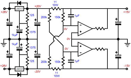
The 200k and 150k resistors set the output voltages. The 1µF feedback capacitors relay all the AC error signal on the power supply rails back to the OpAmps’ inverting inputs, whereupon the OpAmps work to eliminate the error signal, using all their open-loop gain in the effort. (By the way, the AD712s are specified only because I own a dozen of them and I know them to be fairly stable and quiet. I recommend starting with starting with relatively slow, low bandwidth OpAmps before trying exotic, high-speed, wide-bandwidth OpAmps.) Speaking of MOSFETs being internal to an OpAmp, the following circuit uses this topology.
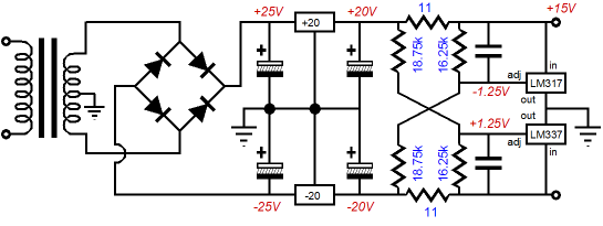
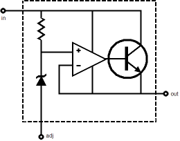
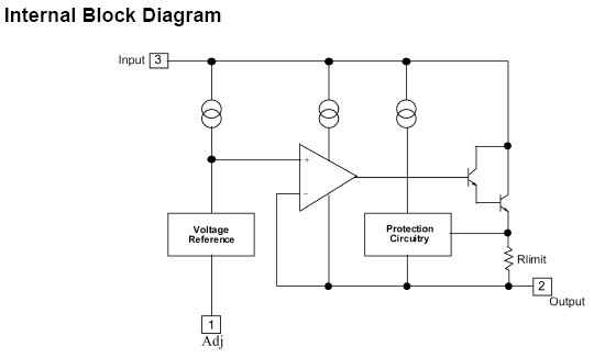
The LM317 and LM337 hold a pass device (a power transistor) and a voltage reference and OpAmp. Configuring these linear regulators in a shunting position—which I do not think anyone else has done before—saves us the hassle of using both OpAmps and power MOSFETs. Functionally, the LM317 looks like the following circuit:
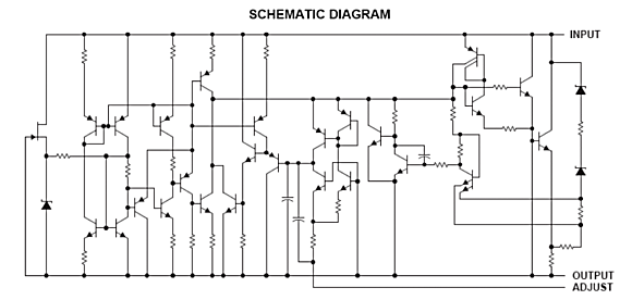
The actual internal circuit looks like this:
And in even greater deatail:
Still, I know that many readers are getting a bit nervous, as all this low-voltage circuitry is creepy enough, but OpAmps on top of it all is just too much. Well, we do not have to use OpAmps or low voltages.
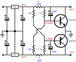
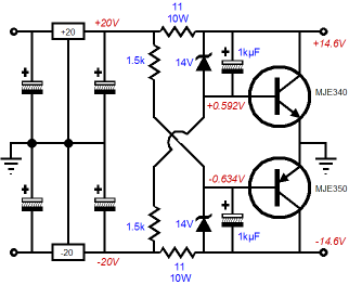
The above schematic displays how to use just two transistors instead. The performance isn’t too bad, but it could be improved by replacing the feedback resistor with zeners as shown below.
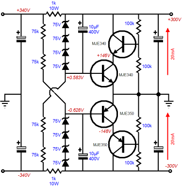
Okay, we lost the OpAmps, but the rail voltages are still far too low for tube-loving folk. You might have noticed that the transistors used were of the high-voltage flavor, so now all we have to do is bump up the voltage, say +/-300V.
The zener strings establish the DC output voltages and the cascoded transistors provide the shunting regulation. (If the rail voltages need to be higher, then more transistors can be placed atop each other; conversely, if the rail voltages need only be +/-150V, then just two resistors are needed, although the cascading feature is well worth retaining, as it eliminates the Miller-effect capacitance at the transistors’ bases.) Those readers with the best memories will remember that at the start of this blog entry, I mentioned two developments that were nudging me to write about shunt regulators again. Alas, I don’t have the time (or the words, as I am over my 1,000 limit by 600) to proceed to the second development today, but I will give a clue: Audio Note patent and feedforward shunt regulators. //JRB * AKA: the False Dichotomy or
Bifurcation or False Dilemma Fallacy. |
Only $12.95
Download or CD ROM www.glass-ware.com
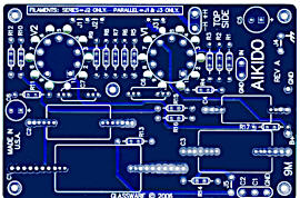
High-quality, double-sided, extra thick, 2-oz traces, plated-through holes, dual sets of resistor pads and pads for two coupling capacitors. Stereo and mono, octal and 9-pin printed circuit boards available.  Aikido PCBs for as little as $24 http://glass-ware.stores.yahoo.net/
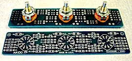
The TCJ Stepped Attenuator The center knob controls both channels, and offers six large decrements; the flanking knobs offer six fine decrements for each channel, creating a volume control and balance control in one easy-to-use stepped attenuator. This clever attenuator uses fewer resistors (only 32) than would be expected from a conventional 32-position stepped attenuator, as two series attenuators would need a total of 72 resistors; and two ladder attenuators would require 140 resistors. In addition, the PCB holds dual sets of resistor pads, one wide and one narrow, so that axial (composition, wire-wound, and film) and radial (thick-film and bulk-foil) resistors can be used without extra lead bending. Although designed to go with the Aikido amplifier, it can be used anywhere a high-quality attenuator is needed, whether passive or active. For example, it would make a first-rate foundation to an excellent passive line box. Visit our Yahoo Store for more details: http://glass-ware.stores.yahoo.net/
The Tube CAD Journal's first companion program, TCJ Filter Design lets you design a filter or crossover (passive, solid-state or tube) without having to check out thick textbooks from the library and without having to breakout the scientific calculator. This program's goal is to provide a quick and easy display not only of the frequency response, but also of the resistor and capacitor values for a passive and active filters and crossovers. TCJ Filter Design is easy to use, but not lightweight, holding over 60 different filter topologies and up to four filter alignments: While the program’s main concern is active filters, solid-state and tube, it also does passive filters. In fact, it can be used to calculate passive crossovers for use with speakers by entering 8 ohms as the terminating resistance. Click on the image below to see the full screen capture.
Tube crossovers are a major part of this program; both buffered and un-buffered tube based filters along with mono-polar and bipolar power supply topologies are covered. Available on a CD-ROM and a downloadable version (4 Megabytes). Download or CD ROM
|
|||


| www.tubecad.com Copyright © 1999-2007 GlassWare All Rights Reserved |