| John Broskie's Guide to Tube Circuit Analysis & Design |
12 February 2017 Post Number 372
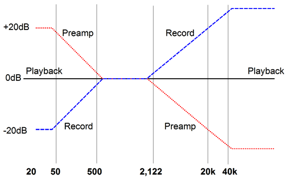
Phono Stages for a Digital World Still, we live in a digital age, wherein babies not yet weaned know how to swipe images across tablets and cell phones. So how do we bridge the world of vinyl to the world of ones and zeros? About a year ago, I dug out my old, long-out-of-pressing, spoken-word LPs and ripped them to my hard-drive, so, while I walked my dogs, I could (with my MP3 player) listen to C. Day Lewis and Marianne Moore read their own poems or hear John Barrymore read Shakespeare. Because these old LPs held only speech, I didn't get too fancy. I used my Tetra phono stage and ran a long length of cable (about 25 feet) from the room where the turntable resided to the room where my computer sat. I used the microphone input on the computer and let its own internal ADC do the analog-to-digital conversion. I then ran anti-tick-and-pop software on the digital files. I was happy to have these old recordings readily available to me, able to stream the data from room to room. I have to admit, however, that the LP sounded far better, more lively, less compressed sounding. The resulting MP3 files sounded inoffensive and bland as canned soup. What went wrong? I know that LPs can be successfully ripped to hard-drive, as I have heard John Atwood do so before. John's system, however, is fancy, very fancy indeed. For example, his sound card costs more than my entire computer setup; hell, so does his computer case. One possibility is that anti-tick-and-pop software scrubbed away, along with the ticks and pops, vitality. I have heard professional refurbishing of historical recordings sound fine, but these might have received the same meticulous attention that classic-movie celluloid receives, where one minute of playing time gets an hour of careful attention. Another possible culprit was the 25-foot length of cheap cable. In addition, few would deem the native ADC chip on the motherboard to be high-end. Then there is the problem of the house-ground connections differing between rooms. As I thought about this problem, a crazy notion came to mind: would it be possible to make phono preamp that produced digital rips that sounded as good as the normal LP playback—and possibly even better? As I said—Crazy—with a capital C. Nonetheless, the idea was intriguing. Working on the assumption that less is more, I wondered if a single tube-based gain stage would suffice. Normally, it wouldn't, as the RIAA equalization curve impressed upon the LP must be inverted by the phono stage, which means that 40dB phono stage must actually provide 60dB of gain at 50Hz and below. And 60dB of gain means an amplification of 1,000, which is more than any single triode can muster, even in a cascode circuit. 20dB = 1 : 10 In contrast, 40dB requires a signal gain of only 100, which doable by a single triode, such as a 12AX7 with a constant-current-source load or a 6DJ8 in a cascode circuit. Where would the extra 20dB of gain at low frequencies come from?
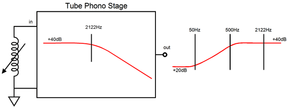
The answer is software. The 3,180µS and 318µS time constants (50Hz and 500Hz) could be achieved in the digital domain by software. The 75µS (2122Hz) low-pass filter would be done by the tube-based phono stage. A hybrid solution of sorts. Why not all software? The ADC could easily be overdriven by the boosted highs from un-equalized LP signals, as the ticks and pops would be un-attenuated. In addition, I trust software to implement the low-frequency boost, but not the high-frequency low-pass function.
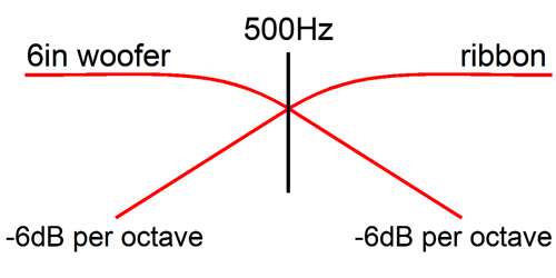
This crazy idea was not entirely new, as over 3o years ago, I had a similar idea. I had been designing and building a bi-ammped system based on the RIAA EQ curves found on LPs. My speakers held a 6in woofer and nearly full-range dipole ribbon, which I crossover at 500Hz.
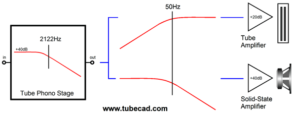
What troubled me was that I had to subtract the 500Hz transition frequency in the phono stage and then add it back in the electronic crossover. I wondered why couldn't I just leave the LP's own intrinsic 500H crossover frequency in place. Of course, the RIAA EQ curve is more complex than a simple 500Hz, 1st-order, high-pass filter. The woofer needed to see the lows below 500Hz boosted and the highs above 2122Hz diminished. The full-range ribbon needed the lows below 50Hz and the highs above 2122Hz diminished. The solution was simple: retain my simple RC filters, but lower the transition frequency from 500Hz down to 50Hz, then build a phono stage that only applied countervailing the top third of the RIAA EQ curve.
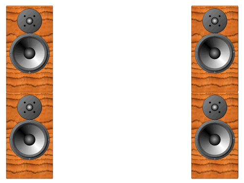
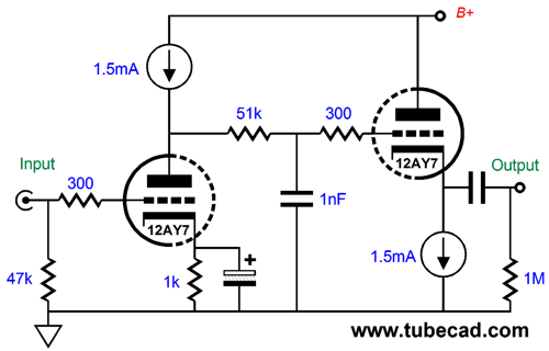
The above layout shows the woofer's amplifier offering 20dB more gain than the ribbon's amplifier. What I actually did, however, was place an OpAmp stage with a gain of 20dB (x 10) after the volume control, so the woofer's amplifier didn't have to supply the missing gain. How did it sound? Starting with the assumption that every mother's child is beautiful, it sounded beautiful. One problem was that the first-order crossover frequency was too shallow for both woofer and ribbon. Another problem was that the woofer resided in an sealed enclosure, while the ribbon operated as a dipole, so the two radiation patterns didn't line up. A better test setup would be to use four identical full-range loudspeakers, with each channel getting a pair of speakers, one atop the other. (See Active Crossovers and Filters.) The four speakers share the same frequency response and phase aberrations and radiation pattern, so as long as they are physically close to each other, their outputs should sum nicely. The phono stage that I built was simple enough:
The 12AY7's own plate resistance became part of the 2122Hz low-pass filter. The 1M resistor was actually a 100k Alps blue volume control. And the OpAmp stage for the woofer's amplifier is not shown, but I do remember the feedback resistor values, 2k & 18k.
So what killed this project? The advent of the CD in 1982. CD's do not come with preformatted crossover frequencies. I will stop here, which will give you time to digest the idea of partial-RIAA-EQ phono stage for ripping LPs to digital audio files. My next post will show some possible circuits.
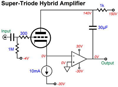
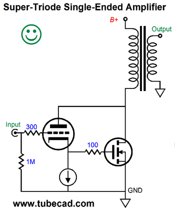
The Return of Super Triode Unlike a MOSFET or transistor, a triode exhibits a low plate resistance. Increase the plate voltage and the triode's current conduction rises; decrease the plate voltage and the conduction falls. This doesn't happen with a MOSFET, for example. A MOSFET's drain is supremely indifferent to the voltage, as long as it is sufficient to turn the device on. With a triode, in contrast, its plate has a say in controlling the current flow through the triode. How much say? The plate is 1/mu as effective as the grid in regulating current flow, where mu is the triode's amplification factor. A 6AS7 presents a mu of 2, so its plate is half as effective as its grid. (The cathode gets more of say, as it is mu + 1 times more effective than the grid in altering the current flow than the grid.) If the triode is going to maintain a fixed current flow and it sees a 1V increase in grid voltage, then either its plate voltage must fall by mu times or its cathode voltage must rise by 1/(mu + 1) volts. The Super-Triode concept exploits the triode's low plate resistance by running the triode under constant-current and using other, bigger, beefier devices, either tube or solid-state devices, to do the hard work of driving tough loads, while letting the triode control the output. Here is a simple example.
The input triode sees an input signal and responds by its cathode following the signal, but as the cathode moves off its idle voltage, the solid-state power amplifier greatly amplifies and inverts the shift in cathode voltage at its output, which then gets relayed to the triode's plate via the 30µF capacitor, creating an active negative feedback loop, with the triode as the controlling agent. If the triode's plate voltage is greater than its amplification factor against the inverted input signal amplitude, the triode will back off giving the solid-state power amplifier its input signal. If the triode's plate voltage is less than its amplification factor against the inverted input signal amplitude, the triode will feed the solid-state power amplifier more input signal. To save me the hassle of reinventing the wheel (or having to redraw the wheel) check out post number 325, which is chock-full of details on the Super-Triode concept. In that post, you will find the following interesting circuit.
The idea behind this circuit is easy enough: the triode runs under constant current, while the N-channel MOSFET experiences all the big current swings. In reality, dang pesky reality, the above circuit is likely to blow up. Why? Nothing stops the MOSFET from drawing too much current. In the following circuit, this problem is avoided.
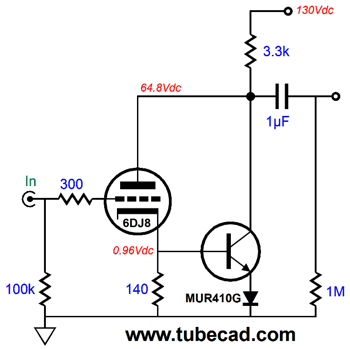
Should the NPN transistor draw too much current, the plate resistor will drop too much voltage, which will lower the 6DJ8's plate voltage to the point where the transistor sees too low a base voltage to conduct too much current. Here is a more elaborate example.
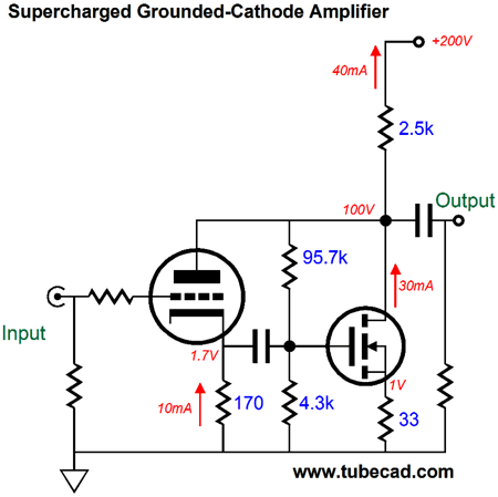
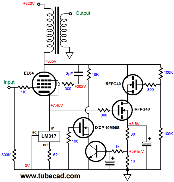
The 2.5k plate-drain-load resistor saves the day. If the MOSFET draws too much current, the plate voltage drops, which the two-resistor voltage divider will relay to the MOSFET's gate, causing it reduce its conduction. If we wish to get fancier, we can replace the 170-ohm cathode resistor with a 10mA constant-current source. If we wish to get even fancier still, we could build something like this.
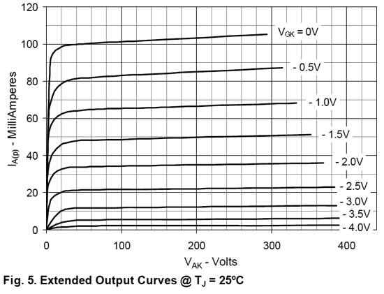
There is so much going on here that I do not know where to start. Okay, let's begin with the tube, an EL84, which is a triode-connected pentode in this example. Note the 3µF capacitor shunting the 10k resistor, which relays 100% of the AC signal at the plate to the screen (grid-2). The next item of concern is the LM317, which sets the idle current for the EL84. The NPN transistor monitors the current flow through the 10-ohm current-sense resistor and the two IRFPG40 power MOSFETs. (Yes, I know that the IRFPG40 is long in the tooth, but I have and trust its SPICE model.) The IXCP 10M90S is a 900V depletion-mode N-channel MOSFET that is sold as an adjustable constant-current source. Here is an excerpt from its data-sheet.
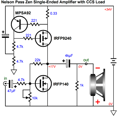
Note that the gate voltage start at -4V and at 0V. This means that at 10mA, the NPN transistor will see about +3.2V at its collector. In a nutshell, the transistor is auto-biasing the MOSFETs by indirectly adjusting the EL84's screen voltage. Now, let's take a look at a Super-Triode take on the famous Nelson Pass ZEN amplifier. If you will remember that amplifier, you will remember that it used an inverting-amplifier feedback loop, whose input impedance was a tough load for tube line stages, due to its 4.k input impedance.
Why not use a 47k input series resistor and a 220k feedback resistor instead? The output MOSFET's input capacitance is far too high to use so high a series resistor. On the other hand, if we use a triode as the input device, we get a truly high input impedance. Indeed, we can forgo the inverting-amplifier feedback loop, as the triode becomes the feedback mechanism.
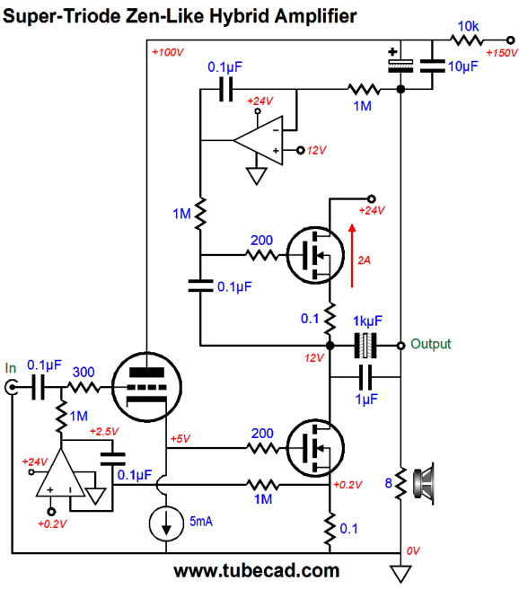
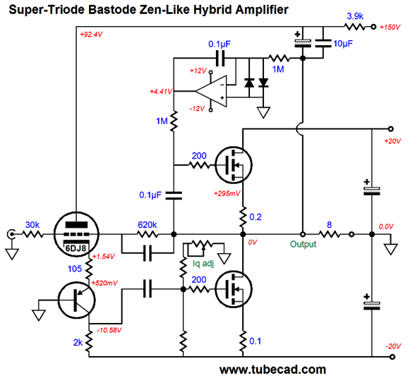
In the above schematic, we see two DC-servos. The top DC servo sets the output at half of the 24V B+ voltage. The bottom DC servo sets the output MOSFET's idle current. The top MOSFET is configured as a compliant-constant-current source. The capacitors that bridge the output to the triode's plate allow the super triode functioning to obtain. The output MOSFET is enslaved by the triode. I know that many readers just despise the idea of a large coupling capacitor at the output. Well, for them, here is a coupling-capacitor-free version.
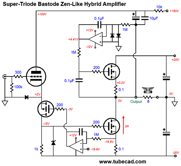
The triode's cathode is no longer terminated by a constant current source; instead, it looks into the P-channel MOSFET's source, which presents a very low impendence indeed. Does the super-triode functioning still obtain? Indeed, it's supercharged. This retrograde cascode (bastode) input stage allows the triode's transconductance to be imposed upon the 1k drain resistor. For example, if the triode's transconductance equals the 10mA/V, then 1V of input signal at the triodes's grid would equal 10V of swing across the 1V resistor. Of course, this never happens. As, the output MOSFET's effective transconductance of 10A/V will force the output sufficiently down to counter the positive grid signal. In other words, the triode's amplification factor sets the gain for this amplifier and governs the MOSFET's operation. A vitally important device is the diode that bridges the ground to the P-channel MOSFET's source. Why? At startup or if the the triode is missing from its socket, the output MOSFET will not get turned on. With the diode in place, the P-channel MOSFET has a current path to ground. Moreover, the cathode will only be -0.7V negative at startup, rather than -20V without the diode. One potential problem is that the bottom DC servo requires an OpAmp whose inputs can dip down to within 0.2V of its negative power supply voltage, such as the OP213. Most OpAmps cannot. Another approach is to use a potentiometer to set the idle current, as shown below.
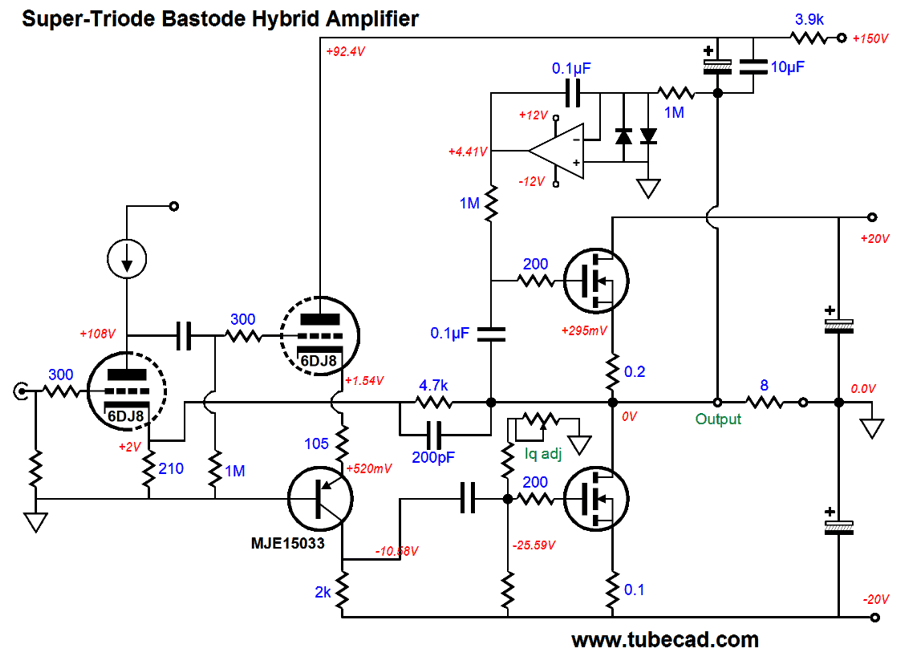
Note that the bottom MOSFET is no longer DC coupled to the collector resistor, so a larger-valued resistor can be used. Also note that a second negative feedback loop has been put in place, for those who need either less gain than the triode would otherwise produce or less distortion or less output impedance than the triode would produce by itself. We can cascade more gain stages, as shown below.
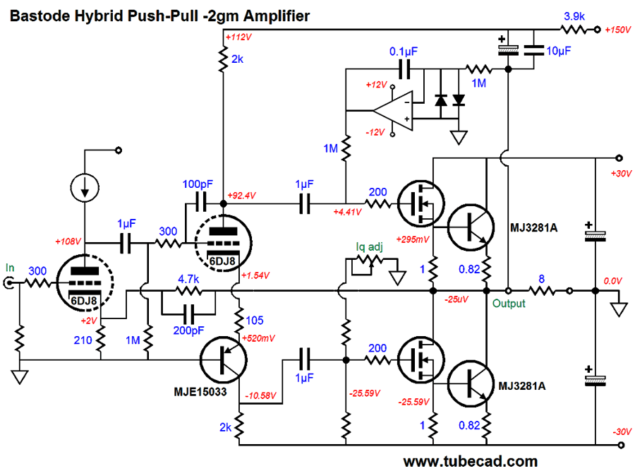
Note that Zen was dropped from the title. Why? We have moved so far away from the concept of one MOSFET sounding that Zen no longer applies. Still, the output stage runs in single-ended class-A. How do we switch over to push-pull operation?
No more Super-Triode. The triode functions as split-load phase splitter and the input triode is in charge. The two NPN transistors are turned off at idle, and only turn on when the MOSFET leave their class-A window of operation. In other words, the output stage is optimized to present a constant transconductance, so as to side step gm-doubling. Returning to JC Morrison's post, towards the middle we find this:
I would like to see a schematic of what didn't work for JC. I assume that AC voltage was used to heat the heater/cathode, not regulated DC.
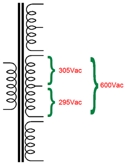
My first thought was that the heater winding was not center-tapped at the exact center. This is a common problem that often shows up with high-voltage secondaries, which gives rise to 60Hz ripple, rather than the usual 120Hz ripple.
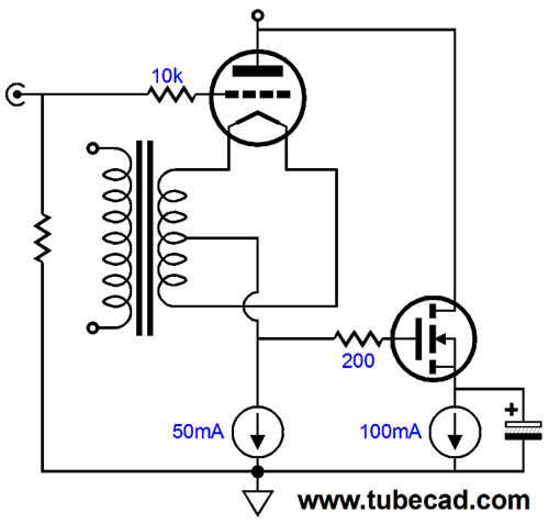
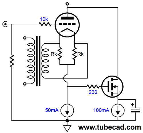
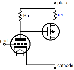
Other than this situation, I didn't see why a directly heated triode could not be used. For example, why would the following circuit by necessity prove noisy?
My first thought was that perhaps if the two cathode resistors were not tightly matched, some 60Hz noise would enter the MOSFET's gate. Then, the more I thought about it, I realized that by necessity this arrangement must prove noisy. My conceptual understanding was instant and complete, but then I had to laugh, as I could not see how I could prove that it was correct. My prediction was that by necessity the unbypassed constant-current source loading the directly-heated cathode must produce a small rectification of the AC voltage applied to the heater/cathode element.
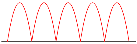
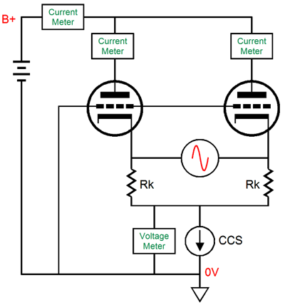
Why must this be so, when the same constant current flows through the plate and the constant-current source? The answer is that the AC voltage applied to the directly heated triode heater/cathode not only heats the heater, it alters the grid-to-cathode voltages. Voltages, with ans "s," not voltage. The average voltage is 0V, but all along the cathode a varying AC voltage is superimposed, with the the very center of the this resistance exhibiting a fixed DC voltage relative to the triode's grid and ground at idle. The average of the entire length of cathode and plate current is what enters the output transformer primary. Now, if the triode were a perfectly linear device, no rectification would occur. Alas, no triode is perfectly linear, not the 2A3, the 300B, or the 845. All triodes are easier to turn on than they are to turn off. This builds in a 2nd harmonic preference, which results in a doubling of the heater's AC voltage in rectified small bumps. In other words, whenever a portion of the cathode experiences a positive heater voltage swing, the current flow from that portion of cathode flows greater than the portion that sees a negative cathode voltage swing decreases its conduction. The less linear the triode, the bigger the amplitude of the bumps. This was my theory, but how could I test it and prove it? SPICE would seem the easy solution, but the SPICE model for 2A3, the 300B, and the 845 do not include separate ends for the directly-heated cathode. Instead, the models treat the cathode as single entity. Dang. Then the more I thought about it, I realized that I could use SPICE, as a single 300B is effectively a vast array of smaller triodes in parallel, but a good approximation would be two triodes: the triode that sees a positive voltage swing on its half of the cathode and the half that sees a negative voltage swing on its half of the cathode. (The irony here is that I know several audiophiles who are adamantly opposed to parallel output tubes in single-ended amplifiers, yet they see nothing wrong with using a single 2A3, not realizing that it is in fact made up of two triodes in parallel within the glass envelope.) I set up the following circuit in SPICE and crossed my fingers.
It took a long time for the smile to fade away from my face, after I ran the SPICE simulation.
I used two 2A3 tubes and a B+ voltage of 200V and a constant-current-source idle current of 120mA (60mA per triode) and heater voltage of 2.5Vac, which was a small mistake, as 2.5Vac actually peaks at 3.54V. (Or was it a mistake due to not using 1.77Vac instead, as two 2A3s were used not one.) The two triode current flows sum to the flat pink line, a total of 120mA. But each triode undergoes +/-8mA current swing from its nominal 60mA idle current. The constant-current source sees a peak of 40mV of 120Hz AC signal. Why is this AC doubling of the heater AC frequency here? The triodes would not sum to a constant-current otherwise, as the half of the cathode that sees a negative heater-voltage swings draws a tad bit more current than the other half of the cathode lets go of tis conduction, so the constant-current source my let the bump up the cathode voltage at ever half cycle of heater AC voltage swing. Since most SPICE models suffer from the assumption of a constant amplification factor, reality will no doubt prove much worse. Morrison's solution was to use the alternate Super-triode arrangement, where the current flow through the triode is monitored at the plate, not the cathode.
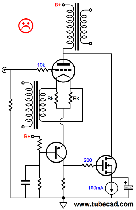
This works, but high-voltage P-channel MOSFETs and PNP transistors are rare and expensive. In general, tubes and high current to not go together well, just as solid-state and high voltage do not go together well. And when dealing with inductive devices, such as an output transformers, and solid-state devices, I worry twice as much as usual. Is there a workaround that would allow us to tap off the cathode and use N- devices, rather than P- devices? Of course there is. (Would I have asked otherwise?) Use DC on the filament, not AC. One thought I had was that the following would solve the problem.
The PNP transistor effectively "grounds the triode's cathode resistors and sums the current flow through each much in the same way as the triode's plate does, so I assumed that the N-channel MOSFET would see no AC rectification signal. It would. The AC heater voltage would still cause a rectification effect, resulting in frequency-doubled current pulses that the PNP transistor would pass on to the collector resistor. The only solution is to use DC on the filaments. So why did Morrison's workaround, using current-sense resistor at the plate work, if he used AC on the filament? He used a 100-ohm plate resistor.
From my SPICE simulations, it looks like the AC heating of the 2A3's filament will give rise to about 0.25mA rectification ripple, which against 100-ohm resistor result in a peak voltage of 12.5mV, which if we treat it as a sine-wave equals only 6.25mV peak. In other words, a 100-ohm is vastly lower in impedance that a constant-current source, or a 750-ohm cathode resistor, that very little of the Super-Triode effect will obtain, but then very little of the rectification effect will be made Super. DC is the real solution.
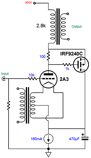
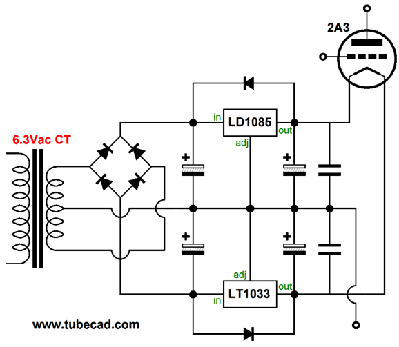
The above regulated power supply for the 2A3 is simple and effective. Both the LD1085 and LT1033 can pass 3A and hold a 1.25V voltage reference internally, so no voltage-setting resistors are needed, as 1.25V + 1.25V equals 2.5V, which is what a 2A3 needs across its filament. With DC on the filament, we return to using N-channel MOSFETs.
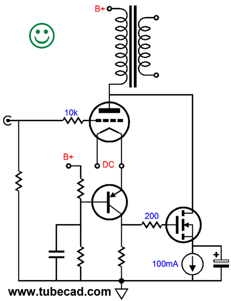
With this arrangement, we can use a 470-ohm collector resistor, rather than a 100-ohm resitor, which means 4.7 times more Super-Triode effect. Note the 100mA constant-current source loading the MOSFET's source. It is there because we do not know just what the voltage drop across the collector resistor will be exactly or what the needed gate-to-source voltage needs to be for the MOSFET. The bypass capacitor shunting the constant-current source must be large enough in value to give the MOSFET something to bite on. If only we could lose these two components. We can. If we are super clever that is.
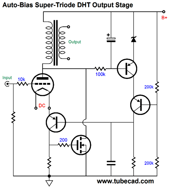
The topmost PNP transistor monitors the DC voltage drop across the output transformer's primary and compares it to the zener's voltage. If the triode and MOSFET are conducting too much current, this transistor will increase it current conduction, which will force the bottommost PNP transistor's emitter to climb in voltage, which will force the triode to cut back its current flow, which in turn will cause the MOSFET ease off its current flow. In SPICE, this won't work, for in SPICE, the primaries, like the inductors, present no DCR. Real transformers, in contrast, do offer resistance, usually between 100 ohms to 300 ohms of DCR. Has your head exploded yet? If not, here is my last attempt.
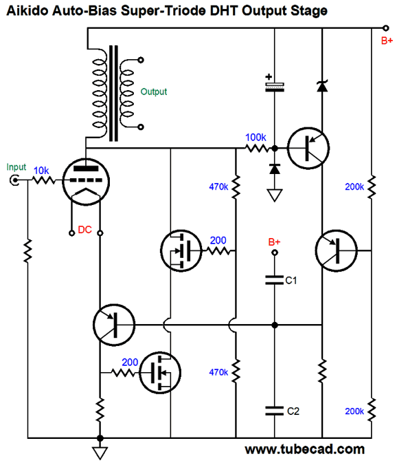
Boom! I can hear all those heads exploding. The two power MOSFETs are placed in series, so they can share both the voltage and the dissipation. The two capacitors, C1 & C2, inject a sampling of the power-supply noise into the output triode's cathode, which forces a power-supply-noise null in the secondary and your speakers. Capacitor C2 must be mu times bigger than C1. Yes, this is my signature Aikido Mojo technique. (See post 348 for more information on this auto-bias arrangement and the Aikido PSRR enhancement of a single-ended output stage.) I will stop here, even though I can add a few more bells and whistles, but then my head might explode.
Next Time
//JRB
If you have been reading my posts, you know that my lifetime goal is reaching post number one thousand. I have 628 more to go. My second goal is to gather 1,000 patrons. I have 970 patrons to go. If you enjoyed reading this post from me, then you might consider becoming one of my patrons at Patreon.com.
User Guides for GlassWare Software
For those of you who still have old computers running Windows XP (32-bit) or any other Windows 32-bit OS, I have setup the download availability of my old old standards: Tube CAD, SE Amp CAD, and Audio Gadgets. The downloads are at the GlassWare-Yahoo store and the price is only $9.95 for each program. http://glass-ware.stores.yahoo.net/adsoffromgla.html So many have asked that I had to do it. WARNING: THESE THREE PROGRAMS WILL NOT RUN UNDER VISTA 64-Bit or WINDOWS 7 & 8 or any other 64-bit OS. I do plan on remaking all of these programs into 64-bit versions, but it will be a huge ordeal, as programming requires vast chunks of noise-free time, something very rare with children running about. Ideally, I would love to come out with versions that run on iPads and Android-OS tablets. //JRB |
Kit User Guide PDFs
E-mail from GlassWare Customers
High-quality, double-sided, extra thick, 2-oz traces, plated-through holes, dual sets of resistor pads and pads for two coupling capacitors. Stereo and mono, octal and 9-pin printed circuit boards available.
http://glass-ware.stores.yahoo.net/ Support the Tube CAD Journal & get an extremely powerful push-pull tube-amplifier simulator for TCJ Push-Pull Calculator
TCJ PPC Version 2 Improvements Rebuilt simulation engine *User definable
Download or CD ROM For more information, please visit our Web site : To purchase, please visit our Yahoo Store: |
|||


| www.tubecad.com Copyright © 1999-2017 GlassWare All Rights Reserved |