| John Broskie's Guide to Tube Circuit Analysis & Design |
21 May 2021 Post 536
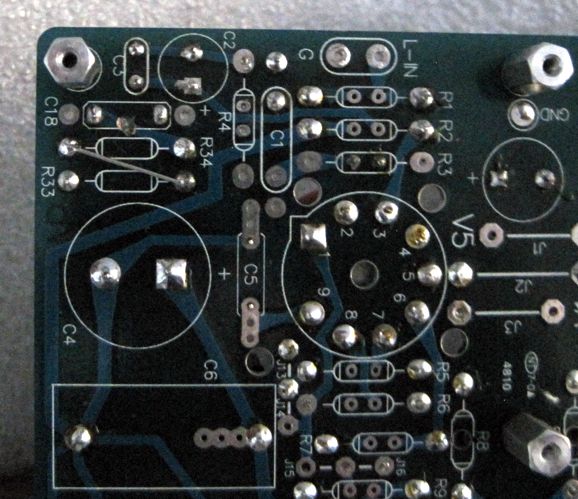
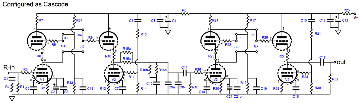
MC High-Gain Phono Stage Update The PCB allows both the traditional Aikido phono stage or an Aikido-cascode configuration; and the second error only applied when the cascode option was selected. The workaround was to cut one trace and to use one of resistor R33's leads to bridge over to R34.
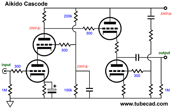
The phono stage holds two Aikido cascode gain stages with a passive RIAA equalization network in between. The input stage is a simple cascode.
The second stage is an Aikido cathode follower (ACF) that undoes the cascode's poor PSRR. Each Aikido cascode stage delivers a gain slightly over 1 : 100 or 40dB, making for a total of 80dB; but the passive RIAA equalization network incurs a -20dB insertion loss, so the final gain is 60dB.
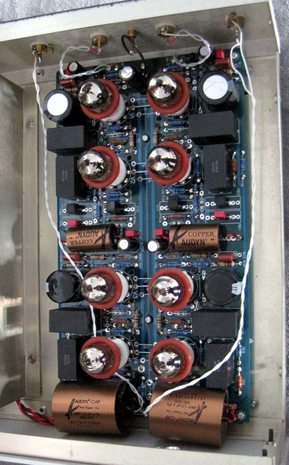
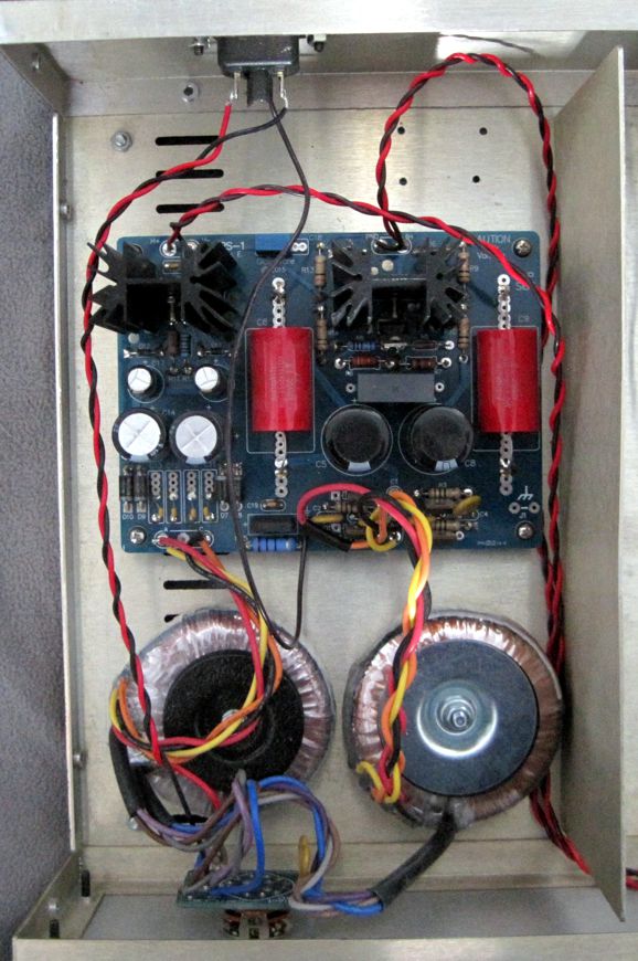
Because of the high-gain requirement, I decided to go all-metal-film throughout. In addition, all the tubes are 6DJ8 types. I also had some fancy capacitors that needed a workout. Sadly, the 1µF output coupling capacitors are so large that they barely fit inside the enclosure.
An internal panel separates the phono PCB from the power supply parts.
So how does it sound? I don't really know. I rushed the assembly so I could bring the unit over to a friend's place, as he owns a low-output MC cartridge. Rushing is a bad idea, as I failed to make two solder joints. It played, but not well, but I didn't know about the two un-soldered connections. In fact, I only discovered them when I took the preamp home and modified it to reduce the gain to 50dB. I cursed myself when I saw the two unsolder joints, as such a failing is normally impossible, as my standard practice is to examine each solder joint with a jeweler's 10X eyepiece. (The practice of re-soldering each joint—a day or two after assembly—would have also caught this blunder and, perhaps, made for better sound.) I listen to the preamp in the 50dB gain setup with my high-output Dynavector 10x5 cartridge, it sounded fine, in spite of the cartridge being loaded by an input resistor 100 times too low. Well, I restored the preamp to the 60dB gain setup, but I have yet to hear it with a low-output MC cartridge. Soon, I hope.
Cynosure Resistor and Aikido Cascode
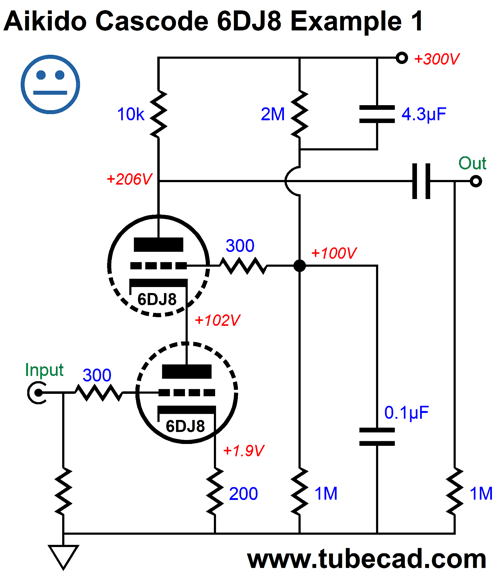
The 4.3µF capacitor couples almost all of the power-supply noise to the top triode's grid, which forces a power-supply-noise null at the plate. Note that the cathode resistor is not bypassed, which means that we will get less gain and less distortion. In addition, a negative feedback loop can be attached to the bottom triode's cathode. This cascode with a 6DJ8 tube puts out a gain of about 1 : 31, which could drive an EL34-based single-ended output stage. Indeed, by adding a split-load phase splitter we can even drive a push-pull output stage.
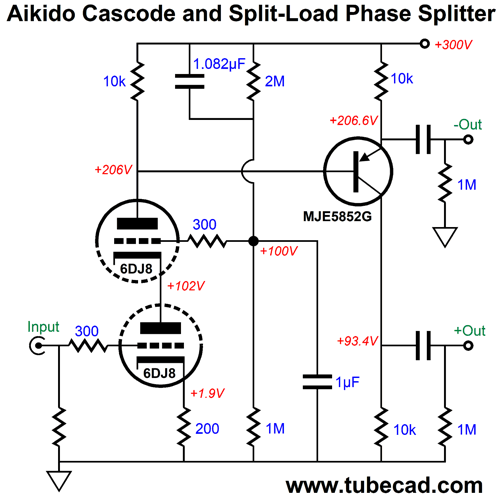
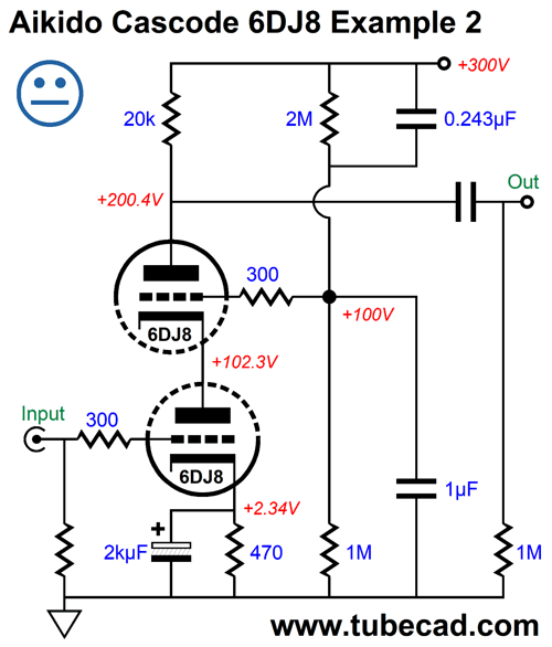
The MJE5882G PNP transistor offers a 400V breakdown voltage, and it allows us to realize much larger output voltage swings, due to the transistor's extremely low potential voltage drop. In other words, where a triode would need 50 volts of cathode-to-plate voltage to sustain its peak current flow, the transistor would be happy with as little as 5 volts of emitter-to-collector voltage. Note that the Aikido mojo capacitor values have been altered, so as to produce an equal and in-phase PSRR from both outputs. Since they do not make a 1.082µF capacitor, we could place a 1µF in parallel with an 82nF capacitor. The problem is that all they must be tight-tolerance capacitors say 1%. If the goal is high gain, the following variation delivers it, as the bypassed cathode resistor increases the gain to 1 : 75.
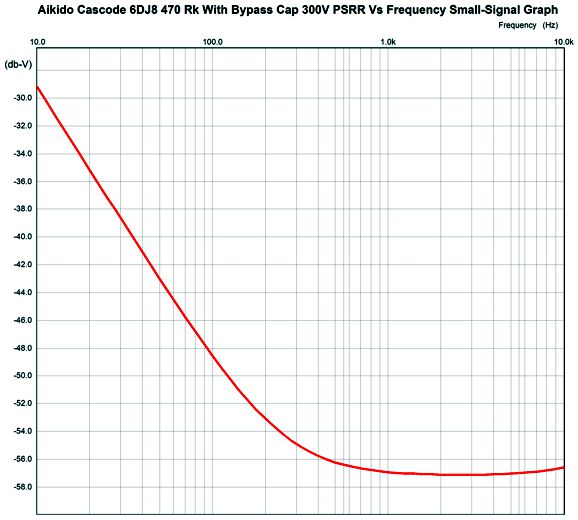
Once again, the Aikido mojo capacitor values have been altered. This time, the top capacitor is smaller in value to the bottom capacitor and we were lucky enough to need standard capacitor values. Here is the SPICE-generated PSRR graph.
If we wish to push the null further down in frequencies, then increasing the cathode-follower's bypass capacitor larger value; instead, using 10µF and 2.43µF capacitor values is the path to pursue. By the way, the logic behind this Aikido arrangement is that the top triode effectively becomes something like a grounded-cathode amplifier, with the bottom triode's plate resistance (rp) acting as a cathode resistor (Rk). The bottom triode's cathode resistor is bypassed with such a large capacitor that the resistor in AC terms does not exist. (If it helps, imagine the cathode resistor being replaced by a battery.) The formula for a triode's effective transconductance with an unbypassed cathode resistor is: gm' = mu/(rp + ( mu + 1)Rk) (Normally, a plate resistor subtracts from a triode's transconductance, so it must be included in the formula; but our assumption here is that the triode will experience a fixed cathode-to-plate voltage, as that is what a power-supply-noise null accomplishes.) Since "Rk" in this configuration equals rp, we can rewrite the formula: gm' = mu/( mu + 2)rp With a cathode-to-plate voltage of 100V and an idle current of 10mA, the 6DJ8's rp is about 3k and its mu is about 30. Let's use these values in the formula to find the gain from the top triode's grid. gm' = 30/(30 + 2)3,000 = 0.0003125A/V or 0.3125mA/V In order to create a power-supply-noise null at the plate we need the top triode's current conduction to increase by 1/10k or 0.1mA. Next, we must find the amount of power-supply noise that must be injected into the top triode's grid, which we find by dividing the increase in current flow by gm', i.e. 0.1mA/0.3125mA/V or 0.32V or 32% of the ripple. In SPICE simulations, the ratio of 0.47µF/(0.47 µF + 1 µF) or 32% produced the deepest null. What if with an actual 6DJ8, we get a different optimal ratio, say 30% or 35%. First of all, why the possible difference? The 6DJ8 SPICE model assumes a fixed amplification factor, which reality fails to deliver across all plate voltages and all cathode currents. Is this the end of the world? No. If we were to collect a dozen fresh 6DJ8 triodes from a dozen tube manufactures, we would get a spread of amplification factors. So was the math useless? Absolutely not. It gets us close, say within 5% to 10%, which is a huge time saver. Now it's time to introduce an alternative scheme, where we forgo using two tight-tolerance capacitors and use a cynosure resistor instead.
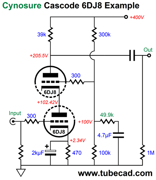
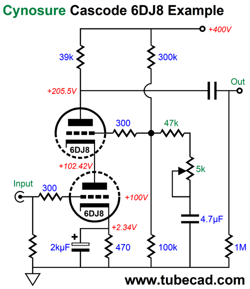
Note the B+ voltage of 400Vdc and the 39k plate resistor and the two-resistor voltage divider made up of 300k and 100k, not 3M and 1M resistors. This is a high-gain cascode, which delivers a gain of 1: 230 or 47dB. Also, note the 470-ohm cathode resistor, which reduces the idle current to 5mA. The 49.9k cynosure resistor is effectively in parallel with the 100k resistor, making a 33.3k impedance to ground. The two-resistor voltage divider created delivers 10% of the power-supply noise to the top triode's grid, as 33.3k/(300k + 333.3k) = 0.1. The 4.7µF capacitor's is not critical, in terms of value, as we could just as easily use a 3.9µF or 6.8µF capacitor; the larger the capacitor value, the deeper the PSRR null extends down in frequency. I ran SPICE simulation to determine the 6DJ8 SPICE model's resulting mu and rp at 5mA and 100V of cathode-to-plate voltage: mu = 30.9 and rp = 3800 ohms. Plugging these values into the effective transconductance (gm') formula and taking in account the 39k plate resistor, the result was 10% of the power-supply noise was needed at the top triode's grid. The key feature here is that if reality fails to conform to either math or SPICE simulations, we can—readily and cheaply— fine-tune the cynosure resistor value; for example, we could try a 47k or a 51k resistor instead. Unlike capacitors, 1% resistors are cheap and readily available. Indeed, since the cynosure resistor sees no DC current flow, we could place a 5k potentiometer in series with a 47k and adjust away.
By the way, one subtlety is to use two potentiometers, one 5k and one 200-ohm in series. We turn each potentiometer to its center position and then adjust only the 5k potentiometer, the coarse control, and then the fine control, the 200-ohm potentiometer. (I included such a set up for tube-based music power amplifier, as the complaint was that the hum null was often jostled off target during the amplifier's transport in the back of a van and it was difficult to adjust, as a very fine adjustment was required with a single potentiometer. With the two-control setup, the coarse potentiometer quickly got close, and then the fine potentiometer allowed for easy fine tweaking.) Okay, let's look at another design example.
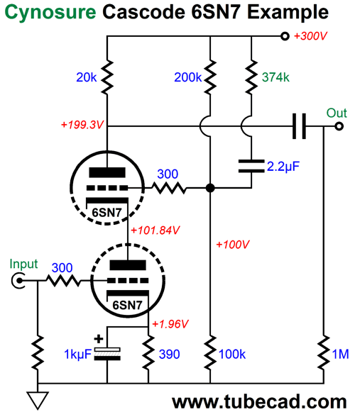
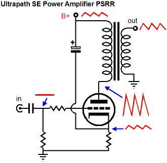
Note the reduction of the B+ voltage to 300V and the 6SN7 tube. Since the 6SN7's transconductance is so weak (2.35mA/V) compared to the 6DJ8 (10 mA/V), in order to get to the larger desired power-supply noise ratio (43%) we must terminate the cynosure resistor into the B+ voltage. What if our goal is a cascode with a PSRR of zero? Why would anyone want an amplifier circuit that leaked 100% of the power-supply noise at its output? In In a word: Ultrapath. In the ultrapath output stage arrangement, the cathode bypass capacitor that normally shunts the cathode resistor bridges the cathode to the B+ voltage.
The problem with this setup is that the bypass capacitor relays all of the power-supply noise to the cathode, where the power-supply noise will be treated by the output tube as a signal to be amplified. Not good. On the other hand, if the input signal arriving at the output tube's grid were also 100% contaminated by power-supply noise, the two noisy elements would cancel, as the plate would also see 100% of the power-supply noise.
If the cathode, grid, and plate all see the same signal, however, effectively there is no signal, as the idle current remains unaltered. If the grid fails to deliver the power-supply noise, then the triode's current conduction must vary with the ripple. I can easily imagine a poor audiophile irked by his noisy ultrapath single-ended power amplifier adding more and more capacitance to the amplifier's frontend end in an attempt to quell the hum, but only increasing it, like a wet dog trying to lick itself dry. Here is one possible design.
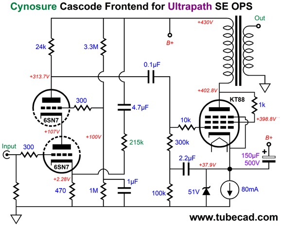
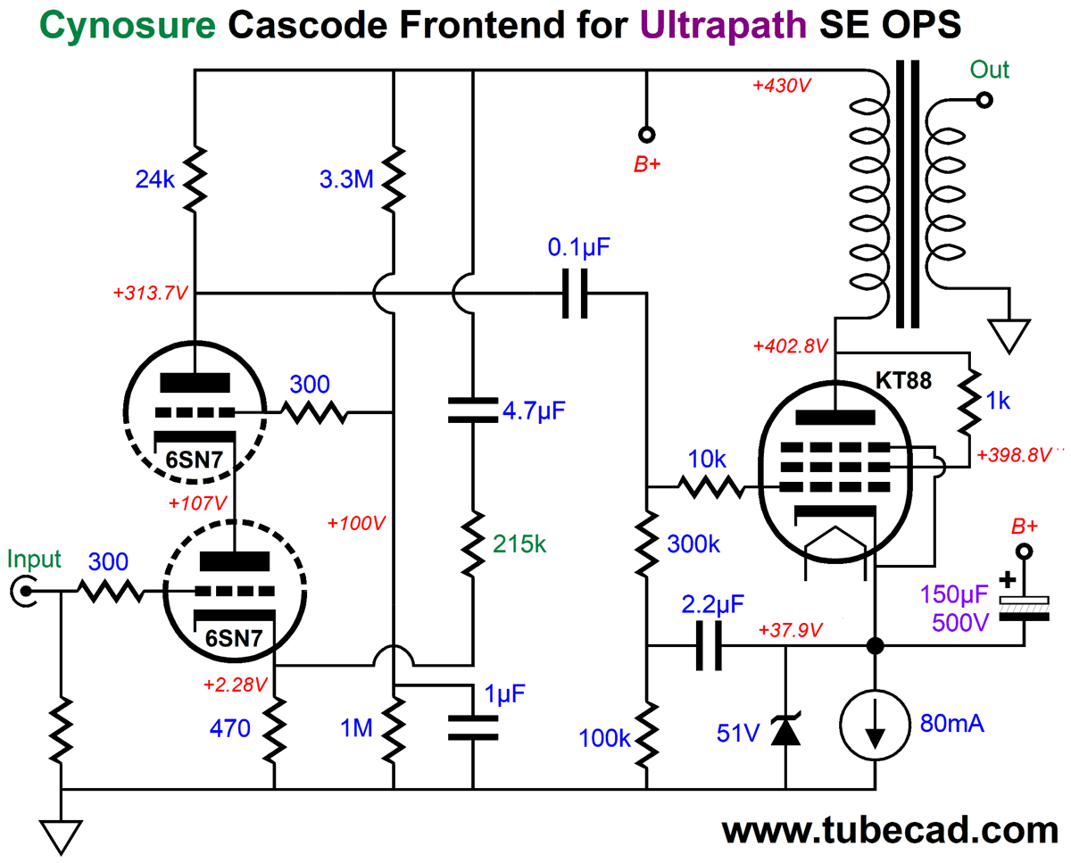
The 215k cynosure resistor reduces the cascode's PSRR to zero, so 100% of the power-supply noise appears at its output. The 80mA constant-current source auto-biases the output tube and nicely decouples the output tube's cathode from ground. The 51-volt zener is merely a safety feature, as it protects the constant-current source from over voltages (the assumption is that an LM317-HV-based constant-current source is used) and provides a discharge path at turn-off, when the 150µF capacitor is still charged up, as the zener will be come forward biased as its anode swings below 0V. The 2.2µF capacitor and the 100k resistor are essential, as they ensure that the power-supply noise is not attenuated by the 300k grid resistor. The KT88 is triode-connected through the 1k screen resistor. To make sense of what is going on, note that the cascode's plate resistor and the output transformer and output tube are all AC signal referenced to the B+ voltage. Effectively, the B+ voltage is the signal ground as far as these components are concerned. As far as the cascode's triodes and the cathode resistor are concerned, ground is the signal reference.
Effectively, the cascode is a voltage-to-current converter, with an extremely-high output impedance, which is aided by the injection of the power-supply noise at its cathode. Here is something to ponder: the output transformer's secondary is not grounded in this schematic. Was that a mistake? We could easily ground the secondary's bottom output lead, but what if we let it float? I have done this before, as my power amplifiers didn't hold a global negative feedback loop. At the time, I thought it improved the sound, but then self-deception and holding audiophile beliefs are pretty much intentionally isomorphic. Here is a thought: what if we "ground" the secondary, not the signal ground or the chassis ground, but to the house ground? Readers have told me that "grounding" the loudspeaker driver frames to the house ground improves the stereo imaging. Well, rather than having an extra terminal on the back of the loudspeaker enclosure that attaches to the house ground via another damn cable, we could simply make the connection internal to the speaker cabinet through the negative input terminal, as it would connect to the house ground inside the amplifier's chassis.
Cynosure Split-Load Phase Splitter Unless a balanced input signal is provided, push-pull power tube-based amplifiers require a phase splitter to drive their output stages. This is true for both OTL and transformer-coupled push-pull tube-based power amplifiers. A phase splitter accepts an unbalanced input signal and produces two output signals, one inverting and the other non-inverting, with each output signal equal in magnitude. A signal transformer with center-tapped secondary can be used as a passive phase splitter. Active phase splitters can be made from solid-state devices, such as FETs, MOSFETs, transistors, and OpAmps; or from vacuum tubes.
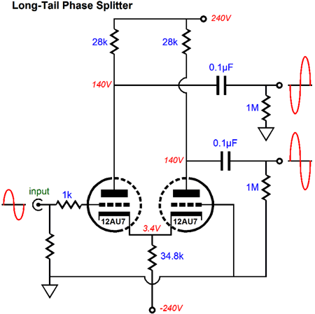
The two most often used tube-based phase splitters are the cathode-coupled phase splitter (aka long-tail phase splitter) and the split-load phase splitter (aka concertina). As we would expect, both offer advantages and disadvantages. The cathode-coupled phase splitter offers signal gain and allows for greater output signal swings for a given B+ voltage. In addition, both its signal outputs present the same PSRR, which is a feature in spite of the PSRR being poor, as the push-pull, transformer-coupled output stage's own common-mode rejection ratio (CMRR) will largely ignore the power-supply noise that leaks from the phase splitter's outputs. (Well, it will at idle and up to the point where it departs from its class-A window of operation, which for most tube-based power amplifiers can be a few watts.)
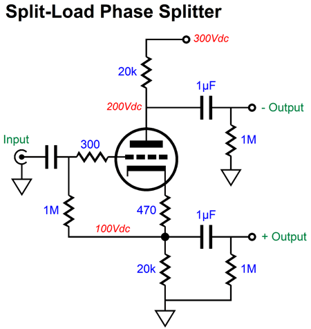
In contrast, the split-load phase splitter delivers a unity-gain (or effectively a gain of two, depending on your perspective); and it presents a great PSRR at its cathode output and poor PSRR at its plate output. Moreover, the split-load phase splitter offers the best balance due to it using a single triode. In contrast, getting perfect balanced from the cathode-coupled phase splitter requires perfectly matched triodes and an infinitely large-valued shared long-tail cathode resistor or a constant-current source. Most NOS twin-triode tubes that were intended for audio use hold triodes that are matched to within 5% of each other. Some held to an even tighter standard, such as the 6SU7, a tightly matched 6SL7 made for use in oscilloscopes. Other twin-triode tubes, such as the 6BX7, were meant to be used as part of TV sets and are often poorly matched. A large-valued shared long-tail cathode resistor implies a large-voltage negative power supply rail. Replacing this resistor with a constant-current source means introducing a solid-state element in our tube-based amplifier and this will offend some sensibilities. In contrast, a split-load phase splitter only requires tightly matched plate and cathode resistors, a trivial undertaking as even nominally 5% tolerance carbon-film resistors actually measure closer to 2% and 0.1% metal-film resistors can be bought. The remaining problems we must overcome are the split-load phase splitter's limited output voltage swing and dissimilar PSRRs. Of course, we may not need huge output signal swings, say, for example, we are driving EL34 or KT88 output tubes, not 300B or 845 triodes. Here is a longish quote from post 167, which is worth reading in its entirety.
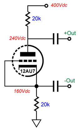
The "Resistor" in the formulas is the value of the cathode resistor (and the plate resistor). To see the logic behind the formulas, here is the assumption.
As the grid connects to the cathode directly, the two elements must share the same voltage, which is what would happen with the maximum peak input signal that does enter positive-grid conduction. The current flow is the peak maximum, so by setting the idle current to half this amount, we get the largest possible output voltage swings. In other words, we have to extremes of conduction: the maximum before positive-grid voltages and completely cut off. The example shown, the peak current flow is 8mA, so we would set the idle current to 4mA and each resistor would see a 80 volt voltage drop.
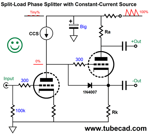
Solving the problem of dissimilar PSRRs requires either brute force or some Aikido mojo. Here is an example of brute force.
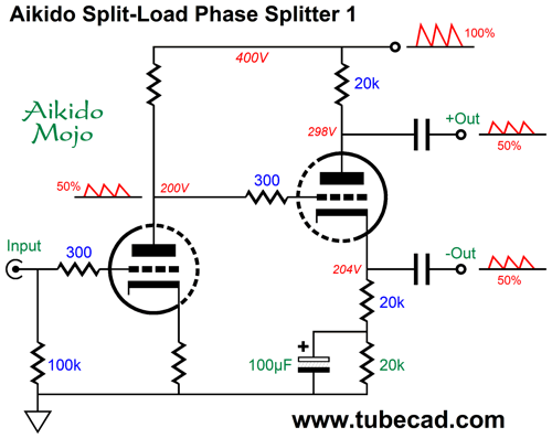
The constant-current source shields the input triode's plate from the ripple and the RC filter scrubs away most of the ripple. Thus, the inverting out will be ripple free, while the non-inverting output will pass on what little ripple remains. Here is an example of AIkido mojo.
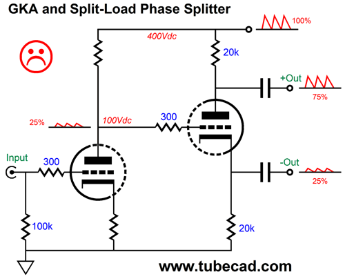
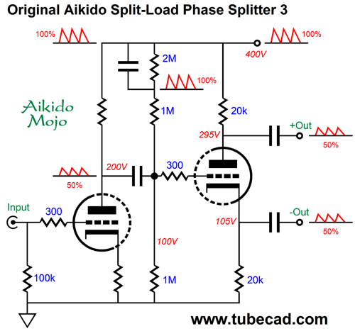
The input stage, a grounded-cathode amplifier, splits the available B+ voltage and delivers a gain equal to half of the triode's amplification factor (mu). In addition, it splits the power-supply noise. The following split-load phase splitter passes on the 50% of the power-supply noise at both its outputs. In other words, we have achieved an equal PSRR of -6dB on both outputs. The magic behind this is simple math. The split-load phase splitter's cathode follows its grid signal, so the 50% of ripple that leaked out of the input stage is impressed on the cathode resistor, which creates a varying current flow that then travels through the phase splitter's triode up through its plate resistor to the B+ voltage. This varying current flow creates an anti-phase signal at the plate that is half that of the power-supply noise, so 1 minus 0.5 equals 0.5.
The 2M resistor is shunted with a capacitor to ensure the injection of half the B+ voltage ripple into the phase splitter's grid. We can use the two-triode totem-pole arrangement here. By adding an internal coupling capacitor, we can run the input stage triode under a higher plate voltage and still give the split-load phase splitter its needed voltage headroom and lower cathode voltage.
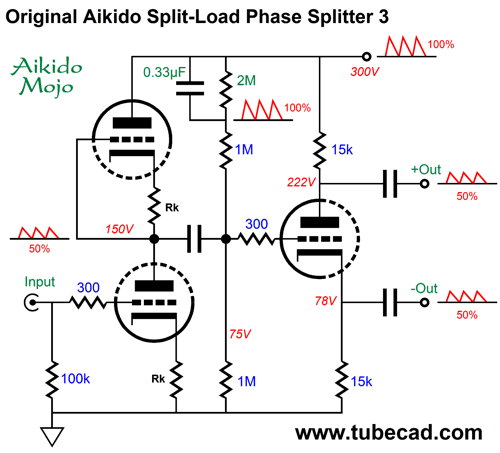
(By the way, this is not an SRPP input stage. Note where the output is taken.) The top triode and its cathode resistor match the bottom triode and its cathode resistor, so we have created a two-resistor voltage divider that halves the power-supply noise. The only problem here is that the maximum B+ voltage should be no more than about 300Vdc, as the top triode's cathode is at half the B+ voltage, so we run the risk of an excessive heater-to-cathode voltage. Another approach is to achieving equal PSRRs is the following.
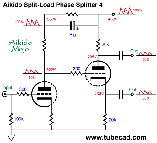
The grounded-cathode amplifier input stage sees two plate resistors, the top bypassed by a large-valued capacitor. The advantage this variation offers is that the grounded-cathode amplifier's plate voltage is only one fourth the B+ voltage, which both gives the split-load phase splitter far more voltage to work with and to maintain a reasonable voltage differential between cathodes. Triodes exhibit a maximum heater-to-cathode voltage, usually 100Vdc. If we reference the heater voltage, either AC or DC, to 50Vdc, each triode will see a 50Vdc heater-to-cathode voltage differential. Another variation I have devised is new to these webpages; or, so I believe, but as I have posted thousands of schematics, it is hard for me to know for sure.
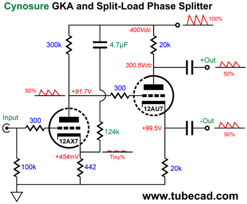
The added capacitor (4.7µF) and resistor (124k) inject a small portion of the power-supply noise into the grounded-cathode amplifier's cathode, which is the amplifier's non-inverting input. Thus, the sampling of ripple is amplified in phase at the plate, so the PSRR at the plate becomes 50%, not the expected 25%. This arrangement allows us to realize greater gain from the input triode and to give the split-load phase splitter a lower DC input voltage with equal PSRR contamination. If a negative feedback loop is added that terminates into the input triode's cathode, the added resistor value might have to be adjusted. Or, it might not have to be, as the feedback resistor is, in DC terms, effectively grounded, it's value must be placed in parallel with the cathode resistor value. In other words, with the negative feedback loop in place, we would need to use a larger valued cathode resistor to attain the same idle current for the input triode; thus, the paralleled value of the feedback resistor and the new cathode resistor value would equal the old cathode resistor value (442 ohms). For example a 464-ohm cathode resistor with a 9.31k feedback resistor, which in parallel equal 442 ohms.
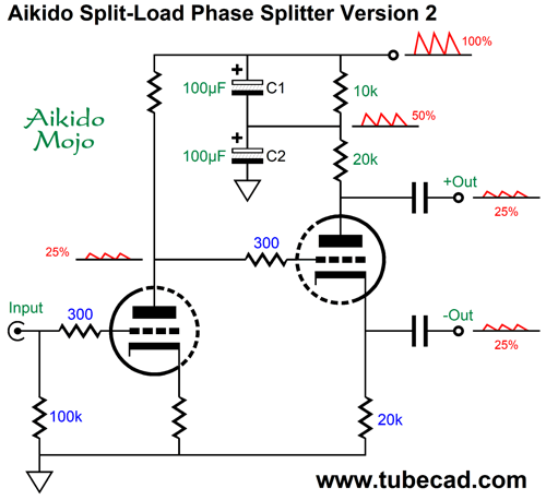
Something Definitely New
The input stage voltage divides the power-supply noise by four. The two capacitors, C1 & C2, AC voltage divide by two. The result is that each output phase of the split-load phase splitter presents 25% of power-supply noise in phase with each other. If the big electrolytic decoupling capacitor is made even bigger in value, we can decrease the 10k RC resistor to as little as 1k. The problem with this solution is that big electrolytic capacitors come in 20% tolerances. You might have to buy ten capacitors to find a tightly-matched pair. (Of course, this is far less of a problem for an audio company, as they buy parts in the thousands.) This is always the problem with trying to implement Aikido mojo techniques with two capacitors, which explains why I prefer using two resistors in place of two capacitors.
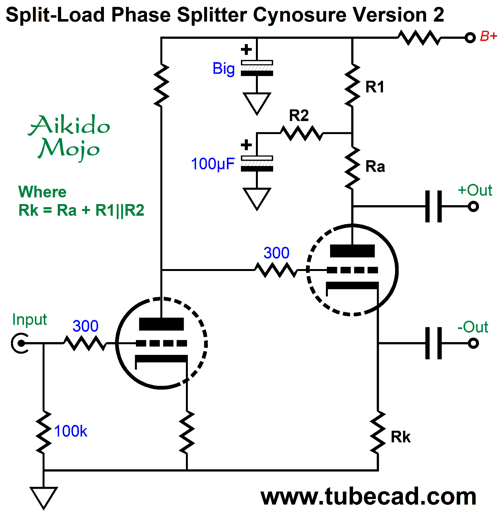
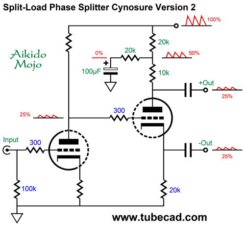
The added resistor, R2, is the cynosure resistor. ("Cynosure" means a center of attraction or attention and derives from the Greek word, Kynosoura, which means dog's tail.) Since the output impedance at the split-load phase splitter plate is so very high, resistors R1 and R2 define a two-resistor AC voltage divider. If we make both resistors 20k in value, then the AC voltage division will be 50%. When we subtract 25% from 50% we are left with 25%.
The split-load phase splitter's balance is retained, as resistors R1 and R2 are effectively in parallel, so their combined resistance is 10k, which when added to the 10k plate resistor results in a 20k plate load, the load the cathode sees. Dang clever, no? Oops, dang sneaky, no? (Actually, the input stage leaks a tad more than 25% of the ripple at its output, as we must include the cathode-follower's failure to produce unity-gain output.)
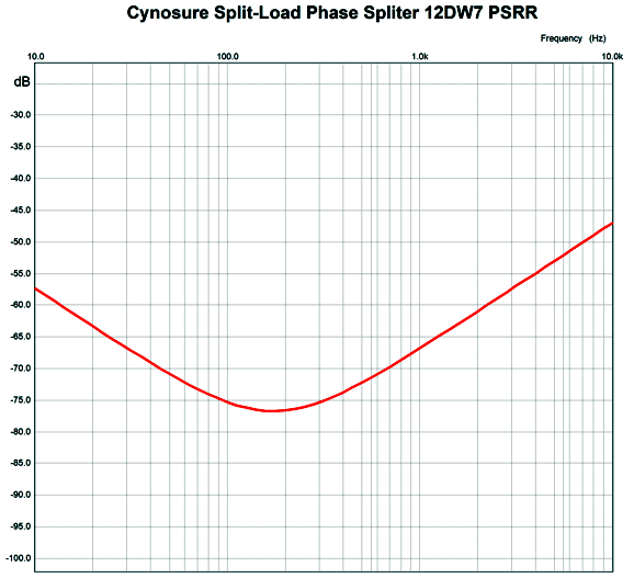
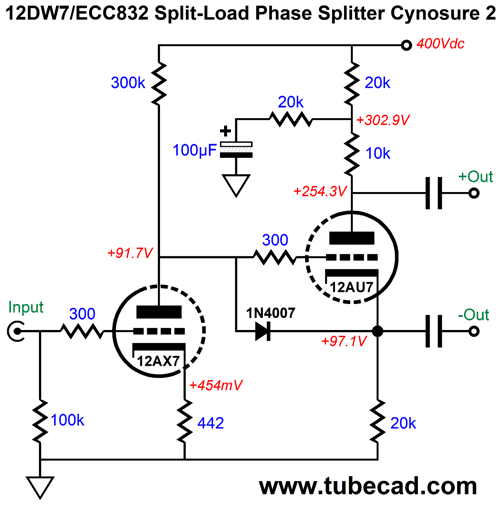
This graph shows the differential PSRR, not the PSRR from each phase output. Remember, the assumption here is that the push=pull OPS's high CMMR will take care of the equal common-mode noise at its inputs. To actually use this phase splitter requires one extra part, a 1N4007 rectifier diode.
At start-up, the triodes will be still cold and not conducting, so the diode will become forward biased and conduct, preventing the split-load phase splitter triode from seeing +400V on its grid, while its cathode sees 0V; not good. Once the triodes are hot and conducting, the diode drops out of the circuit, as the cathode becomes more positive than the grid. The 12DW7/ECC832 dissimilar-two-triode tube is used, which holds a 12AX7 triode and a 12AU7 triode. We could reverse the position of the triodes, so the 12AU7 triode is used as the input tube in the grounded-cathode amplifier and the 12AX7 triode is used in the split-load phase splitter. Yes, we would lose a lot of signal gain, but we might not need the extra gain or we might use a cathode-coupled (long-tail) phase splitter after the split-load phase splitter, as was done in the famous Williamson amplifier.
For more on other Aikido split-load phase splitters, be sure to see posts 231 and 232 and 244.
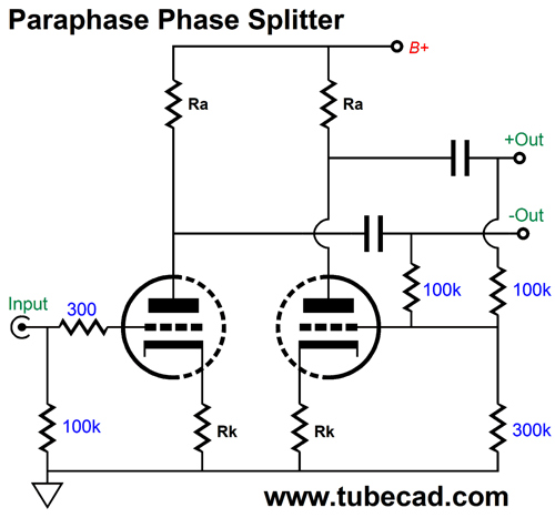
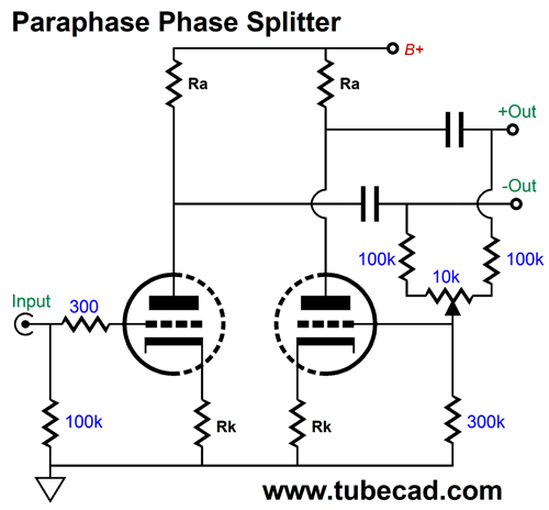
Cynosure Paraphase Phase Splitter
Often a potentiometer is added to allow precise balancing of the outputs.
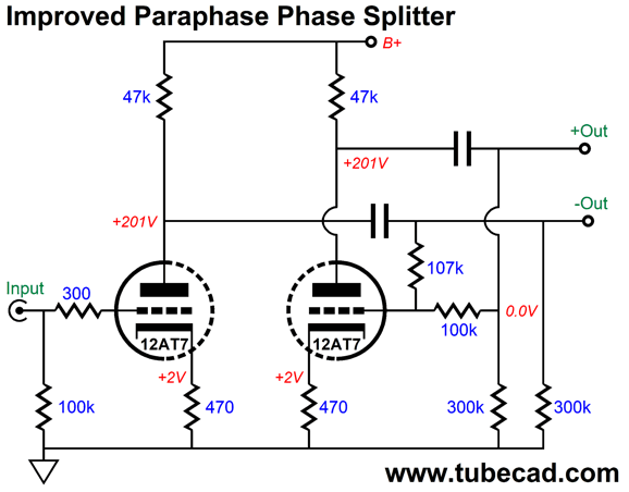
What I dislike about these versions is that the 100k negative feedback resistors and the 300k resistor throw away potential negative feedback, as the resistors function as a voltage divider. Adding an additional 300k resistor preserves the negative feedback.
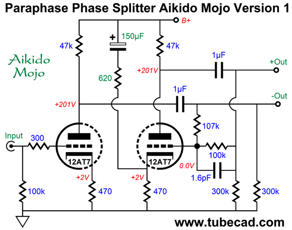
Note the 107k and 100k negative feedback resistor values. This phase splitter does a good job of providing balanced output signals, but suffers from two problems. The first is that the inverting output's high-frequency bandwidth does not match the non-inverting output, as its Miller-effect capacitance and the 100k feedback resistor limit the high-frequency bandwidth. The workaround is to bypass the 100k resistor with a small capacitor. The second is that the PSRRs differ between outputs, egregiously. My solution is the following:
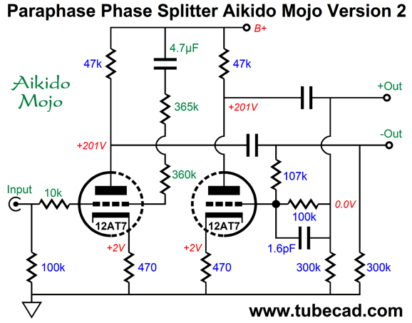
Now, the bandwidth and PSRR are matched. The new problem, however, is the need for a huge 150µF capacitor. This capacitor must be large in value, as the Aikido mojo 620-ohm resistor is so low in value. This irked me, so I sought an alternative that held a far smaller-valued capacitor, which would allow for the use of a film or PIO capacitor.
Note the 10k input resistor, which replaced the usual 300-ohm grid-stopper resistor. The 360k and 365k resistors add up to 725k of resistance. The logic behind this arrangement is that a low-impedance signal source, such as a DAC or an active line-stage amplifier or iPod, is used, so the 10k resistor and the 725k of resistance will define a two-resistor voltage divider that injects a small amount of power-supply noise into the input tube's grid, bringing the two PSRRs in line with each other, both in phase and magnitude. If a high-output impedance signal source—a passive preamp or a volume potentiometer or an SRPP-based line stage amplifier—is used, the Aikido mojo will not obtain, as the high source impedance will ruin the needed ratio. This is not your father's paraphase phase splitter—but it could have been, had he imagined it. This topology didn't have to wait for the invention of a depletion-mode MOSFET or any other new electronic device. All that was needed was a deeper understanding of the circuit's workings and the realization that the power-supply noise is itself an unintended signal source.
Music Recommendation: Morgan James' Quarantunes 1 & 2 These tracks are wonderfully uncluttered and direct. Moreover, Ms. James is a talented singer, capable of jumping from one vocal style to another effortlessly—besides, she is obviously an LP lover.
Tube gear often shines the brightest with simple acoustic reproduction, as the resulting sound is often so much more intimate and lifelike. Both Tidal and Amazon Music Service offer these two albums. Well worth hearing. //JRB
Very few can imagine just how much hard work is required to make one of my posts. If you have any sort of inkling or intuition of what is involved, please think about supporting me at Patreon.
User Guides for GlassWare Software
For those of you who still have old computers running Windows XP (32-bit) or any other Windows 32-bit OS, I have setup the download availability of my old old standards: Tube CAD, SE Amp CAD, and Audio Gadgets. The downloads are at the GlassWare-Yahoo store and the price is only $9.95 for each program. http://glass-ware.stores.yahoo.net/adsoffromgla.html So many have asked that I had to do it. WARNING: THESE THREE PROGRAMS WILL NOT RUN UNDER VISTA 64-Bit or WINDOWS 7 & 8 & 10 or any other 64-bit OS. I do plan on remaking all of these programs into 64-bit versions, but it will be a huge ordeal, as programming requires vast chunks of noise-free time, something very rare with children running about. Ideally, I would love to come out with versions that run on iPads and Android-OS tablets.
//JRB |
|
I know that some readers wish to avoid Patreon, so here is a PayPal button instead. Thanks. John Broskie
John Gives
Special Thanks to the Special 82 To all my patrons, all 82 of them, thank you all again. I want to especially thank
I am truly stunned and appreciative of their support. In addition I want to thank the following patrons:
All of your support makes a big difference. I would love to arrive at the point where creating my posts was my top priority of the day, not something that I have to steal time from other obligations to do. The more support I get, the higher up these posts move up in deserving attention.
Only $12.95 TCJ My-Stock DB
Version 2 Improvements *User definable Download for www.glass-ware.com |
||


| www.tubecad.com Copyright © 1999-2021 GlassWare All Rights Reserved |