| John Broskie's Guide to Tube Circuit Analysis & Design |
| Post 223 09 January 2012 Happy New Year
Since 1980, I have been reading about audio's impending demise. Yet, I am certain that tubes will still rule and are not about to be vanquished. On the other hand, I can imagine wire going the way of the dodo bird. As WiFi insinuates itself into more and more electrical devices, wire, cables, interconnects... become less needed. My laser printer only plugs into the wall socket; computer mice no longer sprout wires, nor do keyboards. How long will it be before the toaster, microwave oven, and the vacuum cleaner are WiFi enabled? And as class-D power amplifiers become even cheaper and more capable, it will make more sense for loudspeaker manufacturers to include them in their speakers, as three class-D amplifiers and an elaborate three-way, active crossover will prove cheaper than one high-quality inductor or film capacitor. Adding WiFi ability will also cost little. Besides, just about everyone hates cables as much as my dog hates his leash—and for the same reasons: they restrict too much and just get in the way.
So, what will high-end audio cable companies sell in a wireless future? My guess is that they will sell high-end audio ether, the all-pervading, infinitely elastic, massless medium formerly postulated as the medium of propagation of electromagnetic waves. (Hey, why not? If failed and outdated Keynesian economics can make a comeback, why not the ether.) Just imagine placing large void-filled containers in between your speakers and the signal source. Or, perhaps, high-end audio wave-guides (a system of material boundaries in the form of a solid dielectric rod or dielectric-filled tubular conductor capable of guiding high-frequency electromagnetic waves) might be the answer. In other words, these would look much like existing high-end audio cables, cost just as much as high-end audio cables, but they will not physically connect to anything. (Will UL approval be needed?) You may laugh, but just wait... Okay, back to 2012. It started out a bit roughly for me, as I spent three days not able to ship through the USPS.com website, as it would always hang at the last step, the printing of postage. Many cryptic error messages came up, but no one at USPS.com knew what they meant; nor did Google reveal any links to an answer. Finally, in a chat with USPS.com representative was the solution revealed: NEVER USE "Ø" CHARACTER IN AN ADDRESS LABEL. That was the problem that blew up USPS.com. Amazing. We have all heard of the dreaded divide by zero error; well, here a capital O with stroke error. The year 2012 just might be the year that I finally get around to updating the structure of this website. It's just too big and ordering it by chronology make little sense. Ideally, I would like to subdivide it into many categories, such as phono stages, line stages, crossovers, headphone amplifiers, hybrid power amplifiers, balanced circuits, I-to-V converters... Then post much more often, but post much shorter entries, which would then move off the front webpage and appear in its appropriate category. (Presently, I only post a third of what I am actually working on and I would like to up the ratio substantially.) In other words, if a reader was only concerned with tube-based electrostatic headphone amplifiers, he could read the long webpage devoted only to tube-based electrostatic headphone amplifiers. We will see.
Single PS Circlotron
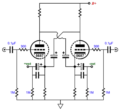
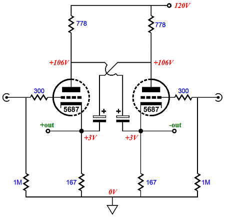
I agree; it does not look like a circlotron circuit. Nonetheless, it functions like a circlotron, exhibiting the same Zo, gain, and distortion. Lets replace the large electrolytic capacitors that cross-couple the triodes' cathodes and plates with 100V batteries.
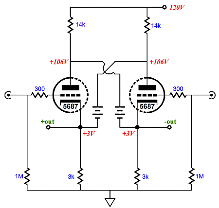
The batteries allow the 5687s to draw 18mA each, while only 1mA flow through the 3k and 14k resistors. In other words, the 3k resistors help set the idle current, but do not flood the triodes with current. In contrast, the large-valued electrolytic capacitors in the previous example act like the batteries in many ways, but they cannot pass DC current, so the cathode and plate resistors much see the same current flow as the triodes do, as they are all in DC series. Since the triodes get all their current from the B+ connection and ground, the capacitor-based circlotron is restricted to class-A operation, whereas the battery-based version is free to break into class-AB. With 300-ohm headphones as the load, class-A is fine; indeed, it is preferred. In order to get the same 18mA of current flow through each triode, much lower resistor values will be needed.
Of course, the 167-ohm cathode resistors could be replaced by 18mA constant-current sources, which leads to this fleshed out design.
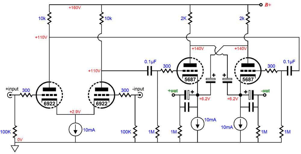
In this circuit, the 5687 triodes run 10mA idle currents and the B+ voltage is 160Vdc. The input stage uses a differential amplifier that can accept either a balanced or unbalanced input signal. The output impedance equals rp/(mu + 2), just as it does in big circlotron power amplifiers. For many readers, this is a good place to stop reading, as they have a workable schematic. Bye. For the rest of us, this is where things get interesting. First, note that the input stage's differential amplifier offers a PSRR of zilch, nada, zip, as all the power-supply noise will be present on its two outputs. Terrible—or is it? The single-PS circlotron output stage also offers a PSRR of 0dB, because of the two constant-current sources. Thus, relative to ground, the balanced output will hold all the power-supply noise, but differentially no power-supply noise will appear. Nice. The headphone drivers really do not care anything about what is going on at ground; their only concern is the voltages across their leads. Couldn't the output coupling capacitors be removed? Only if you like to live dangerously. The only certainty is that both triodes will share the same idle current; but their cathode voltages depend on the tube matching within the glass envelope. Couldn't a DC servo loop be used to force an equal cathode voltage on each triode? Yes, most certainly.
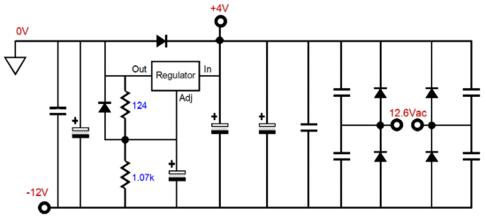
I have added a negative 12V power-supply rail and eliminated the output coupling capacitors. The DC servo keeps the outputs a 0Vdc, even if the 5687 tube is cold and not conducting or pulled from its socket. This feat of magic is the result of including the 1N4001 diodes. Under normal operation, the 5687 cathodes will always be at some voltage positive relative to its grid, so the diode falls out of the circuit, as it is reversed biased. But at startup, when the cathodes are cold, the DC servo's output voltage will swing up positively, as it tries to pull up the output voltage and the diode will turn on, conducting and connecting the DC servo's output directly to the constant-current source, pulling up the output voltage to 0Vdc. (Missing from the schematic is an extra 1N4001 diode that spans from ground to the 6922's shared cathode connection to their 10mA constant-current source, as at startup, we do not want the 6922 cathodes to be at -12Vdc, while the grids are at 0Vdc.) How do you get the +4Vdc power-supply rail? Easy. Just ground the output of a +12V regulator and use its positive input voltage (about +4Vdc) as the OpAmp's positive rail voltage.
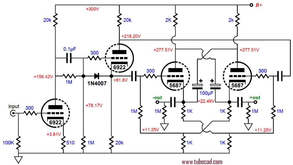
Okay, what if all these solid-state constant-current sources just creep you out? What if you long for a pure-tube version of the above? The following circuit uses cathode resistors instead of constant-current sources and a split-load phase splitter instead of the differential amplifier; in addition, it runs a much higher B+ voltage.
The input grounded-cathode amplifier and split-load phase splitter present a PSRR of -6dB, which means that half of the power-supply noise will leak, in phase and in equal amplitude, from each phase output. The cathode-resistor based circlotron output stage also exhibits a PSRR of -6dB, so the balanced output will also present a PSRR of -6dB. The 2k plate resistors are matched by the two 1k cathode resistors in series, which define a 2k resistance, which, in turn, defines a 50% AC voltage divider with the 2k plate resistors. Once again, differentially, it will not matter to the headphones. Note how we matched kind to kind. Using the above circlotron output stage with a differential amplifier input stage would be a bad idea, just as using the above frontend with the CCS-based circlotron output stage would be a bad idea. Why? We do not want the power-supply noise to mix with (or modulate) the audio signal; we want the 5687 to be oblivious to the power-supply noise. Also note how the "Garter-Belt" bias technique is used, wherein each triode biases the other triode, evening out their idle currents. The 1N4007 diode is there to protect split-load phase splitter triode at startup, when its cathode is at 0Vdc and its grid is at 150Vdc. Why are the output coupling capacitors there? I am just too nervous about burning up my beloved HD650s. (A single coupling capacitor could be used, if its 1M resistor terminated into the other output, not ground. Yes, 22.5Vdc would be present on both outputs.) As a bonus homework problem, can you evaluate what the output impedance is from ground to just one output? Hint: the correct answer will probably amaze you; it's not anything close to rp/(mu + 2). (Before anyone is tempted to e-mail me, asking which version I would build, the answer the the first with the differential amplifier and bipolar power supply and DC servo.)
Next Time
//JRB |
I know that some readers wish to avoid Patreon, so here is a PayPal button instead. Thanks.
John Broskie
E-mail from GlassWare Customers
High-quality, double-sided, extra thick, 2-oz traces, plated-through holes, dual sets of resistor pads and pads for two coupling capacitors. Stereo and mono, octal and 9-pin printed circuit boards available.  Aikido PCBs for as little as $24 http://glass-ware.stores.yahoo.net/
Support the Tube CAD Journal & get an extremely powerful push-pull tube-amplifier simulator for TCJ Push-Pull Calculator
TCJ PPC Version 2 Improvements Rebuilt simulation engine *User definable
Download or CD ROM For more information, please visit our Web site : To purchase, please visit our Yahoo Store: |
|||


| www.tubecad.com Copyright © 1999-2012 GlassWare All Rights Reserved |