| John Broskie's Guide to Tube Circuit Analysis & Design |
19 September 2015 Let it Float Floating Power Supplies
Missing from the dictionary's list is: 7. making no direct connection to the circuit's ground. Floating, in contrast, means that no direct connection to the signal reference (ground) is made. If a 9V battery's positive terminal is attached to ground, or if its negative terminal is attached to ground, then the battery is not floating, but fixed. On the other hand, if neither of its terminals connects to the signal reference (ground), then it is a floating power supply. In my last post, we saw how a floating power supply could be exploited, so that a greatly enhanced PSRR resulted.
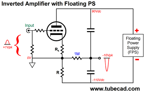
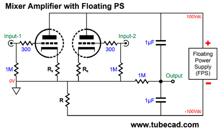
The core circuit was the generic grounded-cathode amplifier, but configured in an inverted topology, which allowed the output to sit at a natural power-supply noise null. Well, can a floating power supply be enlisted to improve other topologies? Indeed, yes. For example, we can use the inverted grounded-cathode amplifier in the following tube mixer circuit.
Each triode gets its own input and the result is a mixer with gain and a high input impedance. Are there any other topologies that could benefit from a floating power supply? Of course there are, such as the split-load phase splitter.
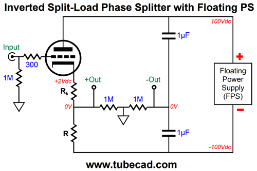
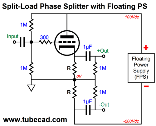
Split-Load Phase Splitter with Floating Power Supply
It does, however, suffer from a dismal PSRR. Well, at least half of it does, the inverting half.
As we can see from the above schematic, the non-inverting output is almost noise-free, but the inverting output is not so lucky, as it leaks just about all of the power-supply noise. These wildly dissimilar PSRR figures are due to the non-inverting output functioning as a cathode follower, whereas the inverting output functions as a grounded-cathode amplifier, with the triode’s plate resistance greatly increased by the huge-valued and un-bypassed cathode resistor. The result is that the plate resistor and the triode with its un-bypassed cathode resistor define a two-resistor AC voltage divider, which barely reduces the power-supply ripple at the plate. If we use a floating power supply and place the signal ground at the mid-point between both outputs, however, we realize a small miracle: equal and fantastically good PSRR from both outputs.
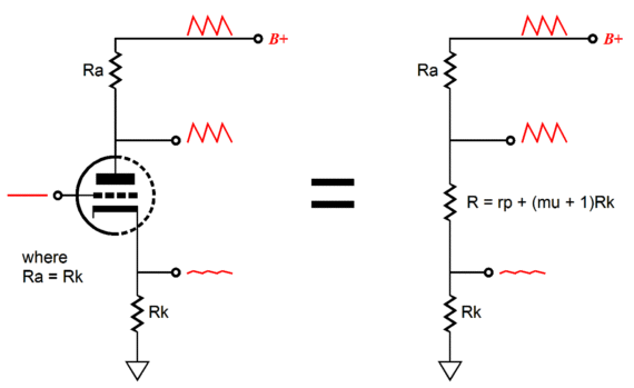
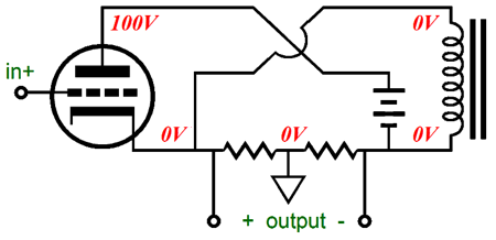
The load resistor R must equal the sum of the triode's plate resistance added to (mu +1)Rk. In other words, replacing the load resistor with a constant-current source is a very bad idea. With this split-load phase splitter, in spite of the floating power supply, all the observations and restrictions that apply to the conventional split-load phase splitter apply equally to this variation, such as the dictum that both phase outputs must see an equal load impedance and load capacitance, otherwise frequency imbalances will arise. Note that only one load resistor is used, not the usual pairing of large-valued plate and cathode resistors. Also note that the ground is not located at the triode’s cathode, as it had been in the inverted grounded-cathode amplifier topology, but in between the two 1M resistors. This is critical, as it makes this split-load phase splitter effectively act like a single-ended Circlotron circuit. Really? The Circlotron’s defining feature is not it fancifully-and-falsely-claimed class-A operation, but its mid-load signal grounding, which makes the Circlotron neither a cathode follower nor a grounded-cathode amplifier but something in between. Here is a single-ended, inductor-loaded Circlotron.
Am I saying that the split-load phase splitter and the Circlotron are cousins? Yes, I am, as they are kissing cousins—indeed, possibly closer. For example, we all know that the split-load phase splitter offers a tad less than unity gain and presents dissimilar output impedances from each of its outputs; but if we place a single load across both outputs, we do get some gain, close to 2, and we do realize a fairly low output impedance. How is that possible?
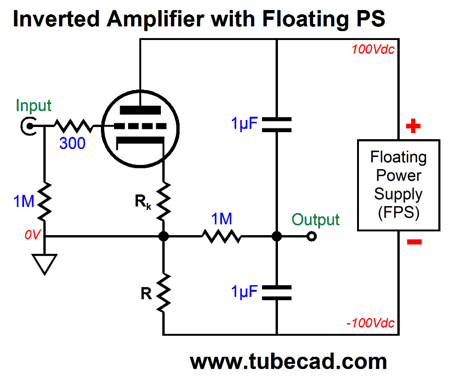
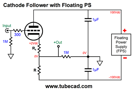
The load is no longer grounded at one end, but mid load, so the two gains add and the dissimilar output impedances are placed in parallel. Read blog number 254 for more information on how the Circlotron and the split-load phase splitters are related. Returning to the split-load phase splitter with the floating power supply, if we move the ground to the triode’s cathode, the circuit becomes an inverted grounded-cathode amplifier,
If we move the ground connection to the nexus of the two coupling capacitors, the circuit becomes a cathode follower, with a floating power supply.
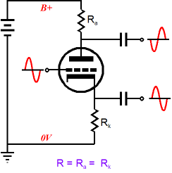
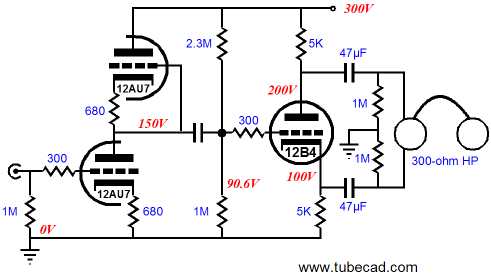
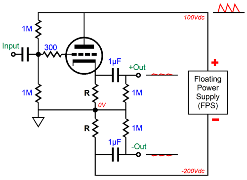
In all three circuits, we realize an enhanced PSRR. By the way, at least one other topology can be made from the split-load phase splitter and a floating power supply. For example, fifteen years ago, in the December 2000 issue of the Tube CAD Journal, we saw the following variation.
Its power supply floats. As the input signal swings up and down, so, too, the power supply. The triode, the two equal-valued load resistors, and the floating power supply define a circle of current conduction. Thus, whatever varying amount of current that flows through one load resistor must also flow through its partner resistor, so the same voltage drops must occur between resistors. Since we have place the signal reference (the ground) between the two load resistors, the two outputs are in anti-phase. Yes, John, it is interesting, but is it useful? A good question, one we should always ask ourselves. The answer is yes, as we realize a much improved PSRR figure.
What is going on here is that plate impedance is huge, relative to the load resistor value, as Zo = rp + (mu + 1)R. If a 12AX7 triode were used with R equal to 100k, the plate impedance would equal 60k = (100 +1)100k or 10,160,000 ohms. The result is the AC voltage division is so great that the amount of power-supply noise leaks through to the load resistors is small. The leaked ripple is out of phase, so it will be amplified by the following push-pull output stage. Still, this variation is vastly quieter than the stock version of the split-load phase splitter. Can we make it even quieter? Yes, all we have to do increase the AC voltage division, so very little of the power-supply noise makes it through to the load resistors and, thus, the outputs.
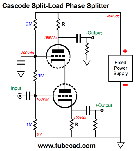
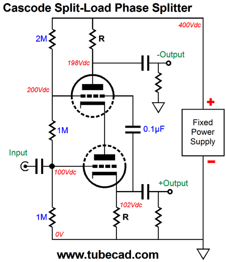
By adding an extra triode to the convention split-load phase splitter, we create a cascoded split-load phase splitter. The result is that the plate impedance at the top triode is huge. In addition, the Miller-effect capacitance gets halved, as the bottom triode sees a fixed plate voltage. In fact, we can lower the input capacitance even further by making the top triode's cathode follow the input signal, as shown below.
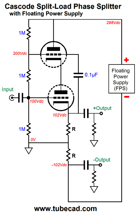
The next step is to use a floating power supply and rearrange the load resistors.
Interesting, no? Actually, I prefer the first split-load phase splitter with its lower power-supply voltage and single load resistor.
I didn't say enough about its cathode resistor, which sets the idle current. Your first thought might be that getting its value right is critical to getting a low DC offset at the non-inverting output. Wrong. Not matter what its value, there will be no DC offset. Think about it: we placed ground between the two 1M resistors, so there can be no DC offset. Really, no DC offset. But, John, what about the case where the cathode resistor's value is zero ohms? Still, no offset. The Idle current will be high, roughly equal to V/(rp + R), and the voltage drop across the load resistor R will be great, but no DC offset at either output. This means as the triode ages or is replaced, we need not worry about a DC offset. (If, on the other hand, we had used a fixed—one grounded at the center tap—bipolar power supply, we would have to worry about the DC offset.) Okay, now that we have had our mental warm-up exercises, we can move on to the harder mental workout.
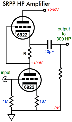
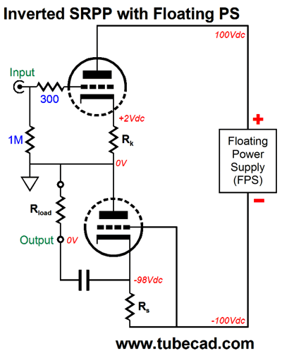
Inverted SRPP with Floating Power Supply
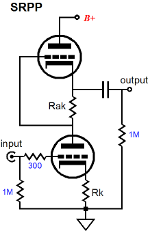
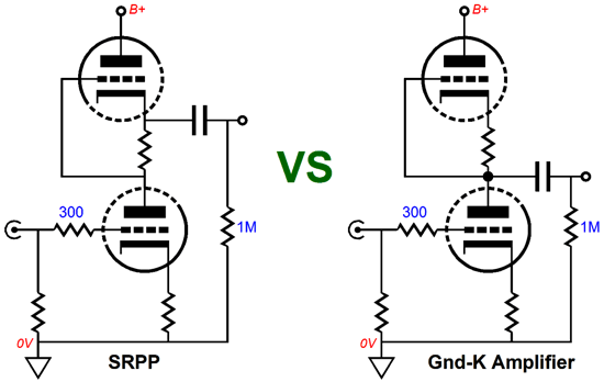
Before I can deliver a quick review of the SRPP's operation, I have to point out that there are effectively two SRPP circuits: the lazy and the hardworking SRPP. The lazy SRPP, like lazy men, predominates. It fills both homemade and high-end audio gear. Driving high-impedance loads, say those above 10k, the lazy SRPP works only halfheartedly, loafing along, but looking cool and stylish. In functioning, the lazy SRPP is much closer to the grounded-cathode amplifier with an active plate-load resistance. In fact, we need only move the circuit's output from the top triode's cathode to the bottom triode's plate to transform the lazy SRPP into a grounded-cathode amplifier with an active plate-load resistance, as shown below.
Why is this SRPP deemed lazy? Two reasons: the designer was intellectually lazy and the circuit barely pushes and pulls, which belies or contradicts the PP (push-pull) in its name. The circuit designer thought that this totem-pole arrangement of triodes nicely took care of the problem of what to do with the vacuum tube's second triode, not because he had a low-impedance load to drive with big current swings. (Besides the SRPP topology is famous, so why not rub shoulders with the famous.) The hardworking SRPP, in sharp contrast, is an industrious circuit, pushing and pulling, working hard to deliver up to twice the idle current into the external load impedance.
Effectively it is a small push-pull power amplifier: an amazingly simple push-pull power amplifier that comprises its own internal phase splitter, in spite of holding only two triodes and two cathode resistors. Actually, this last sentence is not quite accurate, as a vital but unnamed part exists—the load impedance, which is an essential part of the push-pull circuit. The load impedance is a critical part of the optimal SRPP's functioning, which why the SRPP is extremely load sensitive. In other words, for any given pair of triodes and cathode and current-sense resistors in the SRPP topology, there is an optimal load impedance, which allows for the best balance of anti-phase current swings between triodes and which delivers the lowest distortion and peak output power.
Let's move on to a review of the hardworking SRPP's operation. The bottom triode's cathode resistor sets the idle current and can be left unbypassed or be bypassed by a large-valued capacitor. The current-sense resistor in between the top and bottom triodes delivers the top triode's input signal. The lower the load impedance, the bigger the resulting input signal will be. The see how this works, imagine that the external load impedance is a dead short to ground; zero ohms, in other words. As the bottom triode sees an increase in grid voltage, its current conduction increases, all of which must flow through the current-sense resistor, so the voltage drop across this resistor increases, thereby decreasing the top triode's conduction, as it grid sees greater negative voltage. In turn, when the bottom triode sees a decrease in grid voltage, its current conduction also decreases, so the voltage drop across the current-sense resistor also decreases, thereby increasing the top triode's conduction, as it grid now sees less negative voltage. The load impedance was zero ohms, so no voltage drop can occur across it, but the dead short to ground does see a varying current flow, equal to the difference between the top and bottom triode conductions: Iout = Itop – Ibottom. For example, if the idle current is 10mA and no input signal is presented to the bottom triode's grid, the load sees 0mA of current flow, as 10mA -10mA = 0 mA. If the bottom triode then sees a positive input signal and its conduction rises to 15mA, the top triode's conduction will fall to 5mA, and the zero-ohm load will experience a -10mA current flow, as 5mA – 15mA = -10mA. Okay, now that we are all on the same page, let's move on. The quest is for a way to exploit a floating power supply with an SRPP circuit. The keyword in that last sentence was "exploit." It is not enough to create some topology that sort of works, rather we need to exploit the addition of the floating power supply, so we can develop, utilize, take advantage of the addition, thereby achieving enhanced performance, such as lower output impedance or lower distortion or increased PSRR. (Okay, I admit that even if no improvement in performance is realized, a new topology can help us by showing us what is possible, even if it is not preferable.) One variation could be made from the SRPP power amplifier shown in blog post number 320 and shown below.
The fixed bipolar power supply could be replaced by a single floating power supply and the single coupling capacitor could be replaced by two capacitors that would span the floating power supply. Still, the input transformer is a hassle, I must admit. The way out is to rearrange the triodes, so the input triode goes on top.
Once your spell of dizziness passes, you will see that all the same parts are here, but differently arranged. A cathode and current-sense resistor, two triodes, an external load that terminates into ground and a large-valued coupling capacitor, and the same 200V power supply. In functioning, this inverted SRPP behaves just like its conventional brother circuit. The top triode's cathode resistor sets the idle current and can be left unbypassed or be bypassed by a large-valued capacitor. The current-sense resistor at the bottom triode's cathode delivers the bottom triode's input signal. The external load impedance sees the difference in conduction between top and bottom triode. It's all the same, but upside down.
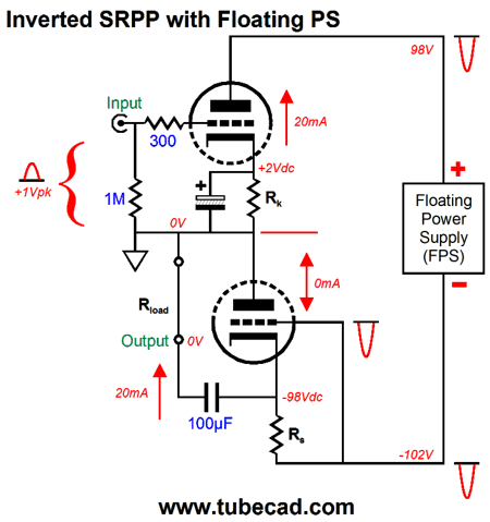
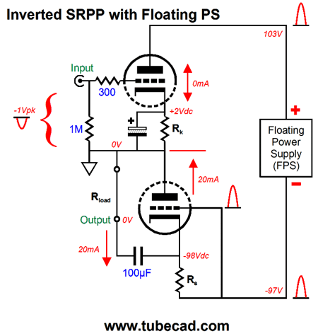
Above, we see what happens when a positive pulse is applied to the input triode's grid. The top triode increases its conduction up to 20mA, while the bottom triode drops its current conduction to 0mA. The delta, the difference is +20mA, which the external load experiences. If the input pulse is inverted, the following results.
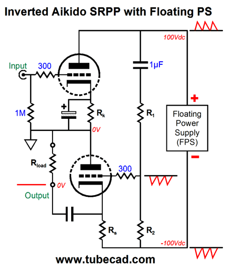
The top triode cuts off, while the bottom triode now conducts 20mA. The delta is -20mA, which gets delivered into the load. Now, some of the more alert readers having been wondering where does any real performance enhancement enter this picture. It doesn't. As it stands, we have not really gained anything from the inversion and floating power supply. But by adding an Aikido twist, we do get a greatly enhanced PSRR.
By carefully selecting the values of resistors R1 & R2, we inject enough ripple into the bottom triode's grid to create a power-supply noise null at the output. Magic or is it something akin to... ? By the way, I have received e-mails from readers, almost always from Asia, either from Hong Kong, India, Japan, or Taiwan, which ask for additional material on some new circuit that I have posted, such as the one above. I reply that I might feel compelled to return to the novel circuit in some upcoming post. This reply then prompts the second e-mail that states that the reader isn’t really interested in what I may have say about the circuit, for what he wants is references to old electronic textbooks or journal articles that would further explicate the circuit, written by the old masters, such as Crowhurst, Eastman, Hill, Langford-Smith, Millman, Seely, Spangenburg, Terman, and Termaine. My second reply points out that the circuit was new, hitherto never conceived, sui generis, newborn, fresh, novel, and original. Here the e-mail exchange usually ends. Mind you, if I had a time machine and could travel back to 1955 and show Norman, Austin, Fritz, W. Ryland, Jacob, Samuel, Karl, and Howard my new tube topology, they would be the first to pat me on the back and buy me a beer.
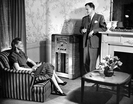
Ah, those were the days, when men were men and sound systems warmly glowed.
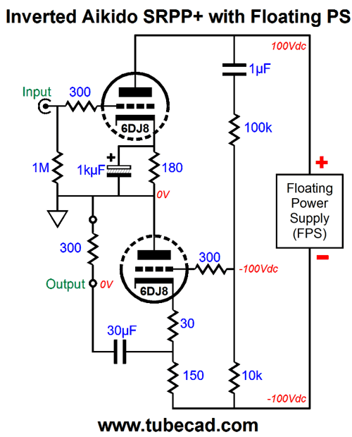
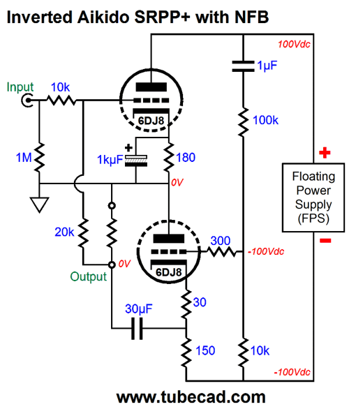
Let's finnish up with an actual design example.
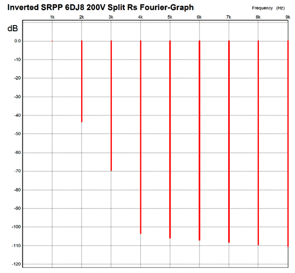
Note how the single current-sense resistor was replaced by two resistors, making this circuit an SRPP+ topology. With 1Vpk into 300 ohms at 1kHz, we see the following SPICE Fourier graph of the resulting distortion harmonics.
Note the very single-ended nature. The next graph show the current swing balance between triodes, the push-pulling operation, in other words.
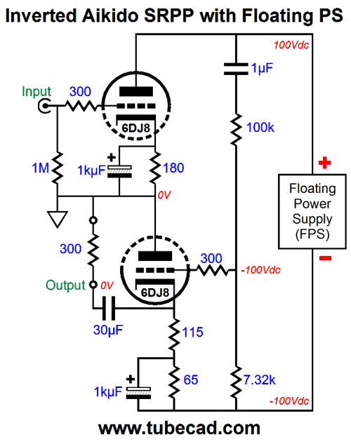
The 10k and 20k resistors set a fixed gain of about 2 or +6dB. An alternative variation is the following, which loses the "+" from its title, as only one current-sense resistor is used.
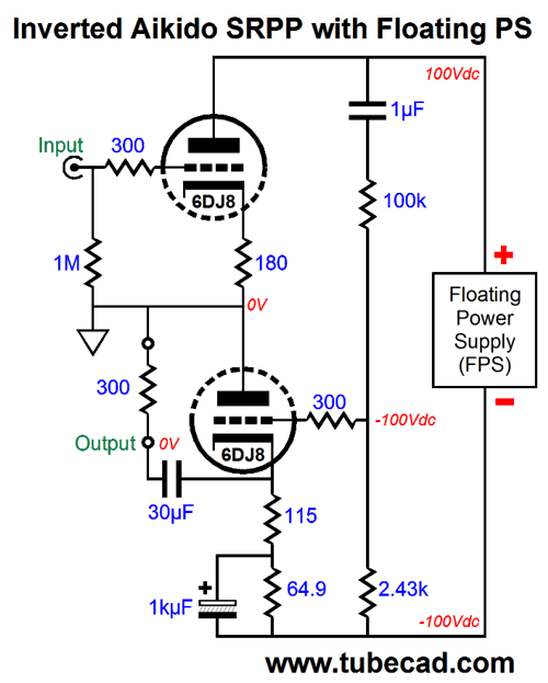
Note the change in R2's value, from 10k to 7.32k. Also note that the 115-ohm current sense resistor value falls in line with the formula: Rsense = (rp + 2Rload)/(mu -1), as a 6DJ8's rp is about 3k and its mu about 30 at 10mA at 100V from cathode to plate. A new question is What happens if we forgo the use of the bypass capacitor on the top triode's cathode resistor? We lose a lot of gain, but we also lower the distortion. We must alter resistor R2's value to create the power-supply noise null.
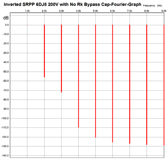
Here is the Fourier graph from SPICE for the same 1Vpk into 300 ohms at 1kHz.
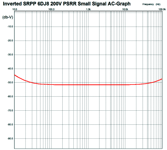
Much more to my liking. I have not mentioned output impedance. Many falsely believe that the SRPP's output impedance is crazy low. It's not. In fact, the above variations an output impedance of about 1,700 ohms, not the 50 ohms that some might imagine. Nor have I mentioned the actual improvement in PSRR. Without the the Aikido pair of resistors, R1, & R2, the PSRR is about -15.6dB; with the resistors, about -51.5dB. In actual practice, getting -40dB should be easy; and if you have the skill and patience, -60dB could be obtained. The nest question is What does the frequecy response plot look like for the enhanced PSRR?
Not bad at all. Note that the important frequency is twice the wall voltage frequency: 120Hz here in the States; 100Hz, in Europe. Well, once again I managed to create a much bigger, longer post than I ever intended. Perhaps, it is a good thing that Misters Crowhurst, Eastman, Hill, Langfor-Smith, Millman, Seely, Spangenburg, Terman, and Tremaine have passed on, as I don't know how my back would take all those pats or my head all those beers.
Next Time
User Guides for GlassWare Software
For those of you who still have old computers running Windows XP (32-bit) or any other Windows 32-bit OS, I have setup the download availability of my old old standards: Tube CAD, SE Amp CAD, and Audio Gadgets. The downloads are at the GlassWare-Yahoo store and the price is only $9.95 for each program. http://glass-ware.stores.yahoo.net/adsoffromgla.html So many have asked that I had to do it. WARNING: THESE THREE PROGRAMS WILL NOT RUN UNDER VISTA 64-Bit or WINDOWS 7 & 8 or any other 64-bit OS. I do plan on remaking all of these programs into 64-bit versions, but it will be a huge ordeal, as programming requires vast chunks of noise-free time, something very rare with children running about. Ideally, I would love to come out with versions that run on iPads and Android-OS tablets. //JRB |
Kit User Guide PDFs
E-mail from GlassWare Customers
High-quality, double-sided, extra thick, 2-oz traces, plated-through holes, dual sets of resistor pads and pads for two coupling capacitors. Stereo and mono, octal and 9-pin printed circuit boards available.  Aikido PCBs for as little as $24 http://glass-ware.stores.yahoo.net/ Support the Tube CAD Journal & get an extremely powerful push-pull tube-amplifier simulator for TCJ Push-Pull Calculator
TCJ PPC Version 2 Improvements Rebuilt simulation engine *User definable
Download or CD ROM For more information, please visit our Web site : To purchase, please visit our Yahoo Store: |
|||


| www.tubecad.com Copyright © 1999-2015 GlassWare All Rights Reserved |