| John Broskie's Guide to Tube Circuit Analysis & Design |
| Post 215 10 October 2011
RIP Steve Jobs
PCB Update
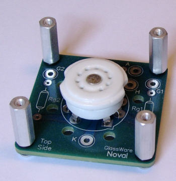
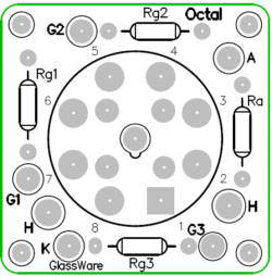
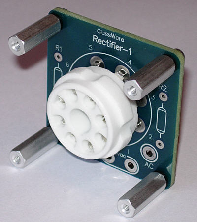
Well, all the Tetra Sans PS PCBs are sold. It was quite a ride, although far too short. Do not despair; more will be made. In the mean time, the following new PCBs might help you out in your next project. These are small, 2 by 2 inch, PCBs that are designed to hold a single tube socket and a few resistors. Many, myself included, like to see tubes protrude from the chassis top panel, like missiles leaving their silos. These boards help make that possible. These PCBs can also be used inside the chassis, on its bottom, of course. Indeed, they could be mounted 45 degree angle, like a V8 engine.
Each PCB comes with a ceramic tube socket and four sets of aluminum hex standoffs (0.75in or 0.5in) and rubber O-rings and screws. The PCB material is thick (0.93in) and tough (2 oz copper traces), so there is no chance that it will bend, when the tube is pulled from or pushed into the socket.
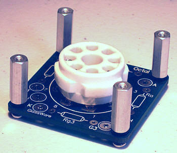
The PCB also hold pads for grid-stopper and plate-stopper resistors. Plate-stopper resistor? What's that? A plate-stopper resistor is usually a 10- to 100-ohm resistor that comes between an output tube's plate and the output transformer lead. It, like the grid-stopper resistor, stops oscillations. A ten cent miracle, which is sadly absent from most tube power amplifiers. The octal PCB is meant for use with tubes such as the 6L6, EL34, 6500, KT66, KT77, and KT88...
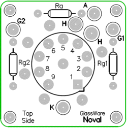
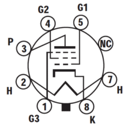
Note that the these pinouts refer to the bottom of the tube, not the top. The noval PCB is meant to be used with 6BQ5/EL84 output tubes.
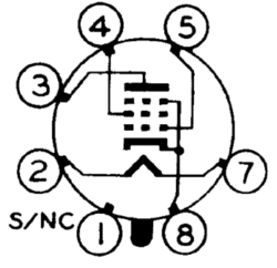
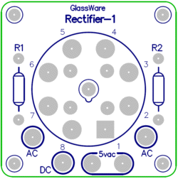
The third new PCB is for a tube rectifier, such as the 5R4, 5Y3 or 5AR4/GZ34.
Two resistors are used on the PCB, as is required by most tube rectifiers when working directly into a reservoir capacitor. These resistors limit the peak current into the capacitor. All three PCB kits are available now at the GlassWare Yahoo store.
Over/Under OTL
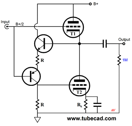
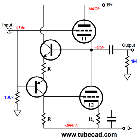
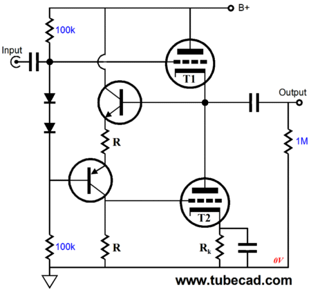
The above circuit is a push-pull, tube-based OTL that holds a transistor-based, feedback-based phase splitter of sorts. These two transistors and two resistors work to keep the two triodes delivering balanced current swings in the external load. Unlike a true phase splitter, this circuit does not present two anti-phase outputs; instead, it samples and evaluates the the top triode's cathode-to-grid voltage and inverts this voltage signal and presents it to the bottom triode, thus ensuring balanced push-pull operation of the output tubes, regardless of the load impedance. Magic. In greater detail, the top transistor samples the OTL's output at its base, whereas the bottom transistor see its input signal at circuit's input. If both these signals follow each other perfectly, no current variation would flow through the bottom resistor R, which means no signal would develop for tube T2. But of course, there is usually a difference, which in turn will cause a current variation to flow through the bottom resistor R, creating an input signal for tube T2. When I see a new amplifier or buffer circuit, much like a detective arriving at a murder scene, I like to work backwards. Imagine a positive-going pulse applied to the output, This pulse will force the T1's cathode to move more plosive to its grid, thereby forcing the triode's current to fall. In addition, it will force the top transistor's base more positive, which will increase the current flow through this both transistors and resistors, which will develop a positive-going pulse across the bottom resistor, forcing T2 to increase its current conduction. If the pulse is 1Vpk, then the pulse at T2's grid will also be 1Vpk, so the two triodes will respond equally to this pulse. Working from the beginning, imagine that the output is shorted to ground and that the coupling capacitor is large enough so that it is effectively a dead short to ground for AC signals. Now, we apply a 1Vpk a positive-going pulse to the circuit's input. The top triode, T1, sees its grid voltage rise by 1V and its cathode voltage remain fixed, so it's current conduction rises by 1V times it transconductance, say 10mA/V, or 10mA. Thus, if its idle current, Iq, is 15mA, its conduction will rise to 25mA. The bottom transistor's base sees the 1Vpk positive-going pulse and its emitter follows, which decreases the voltage drop across both resistors by 1V, so the bottom triode, T2, sees its conduction fall by Iq - 1V x gm, or -10mA; thus, its conduction will fall to 5mA (don't forget that the idle current was 15mA). The load, a dead short to ground in this case, sees the delta, the difference in current conduction between triodes, or 20mA. Yes, the output voltage remains fixed, 0Vdc, but the current flow up from ground through the coupling capacitor and T1 is 20mA. This the worst-case test, which the topology passes beautifully. Let's say that 100-ohm load is attached and that the 1Vpk positive-going pulse results in a 0.8Vpk positive-going pulse across the resistor. This means that both the top and bottom triodes effectively saw a 0.2Vpk input signal. The top triode's signal was in phase with the output; the bottom triode, in anti-phase. By the way, we can easily use this topology with a bipolar power supply.
By adding an input coupling capacitor and a DC servo loop, we can eliminate the coupling capacitor and DC couple the output to the load. Which tubes would work well in this circuit? Many triodes come to mind: 6BX7, 6BL7, 6CG7, 6DJ8, 6H30, 12AU7, 12B4, 12BH7, 5687, and the ECC99. The potential problem is that the triode may not develop enough cathode-to-grid voltage to allow for the two transistor voltages drops and the voltage across the top resistor, R. The voltage across the resistor between the two emitters must be great enough to shut off the bottom triode, when no current flows through the bottom resistor. This the only real limit, as we do not have to worry about turning on either top or bottom tubes to full current conduction. In other words, this over/under output stage topology is not bound to class-A operation, as is the White cathode follower, as an over/under OTL can run in a lean class-AB. The big advantage that class-AB offers is power. For example, with a White cathode follower, the maximum symmetrical current swing into the external load is twice the idle current. In contrast, the over/under OTL can develop huge current swings far bigger than twice Iq, as this phase splitter is not dependent on the current flowing through the top tube for its input signal. Still, we want enough of a negative going signal to reach the bottom triode's grid to cut this tube off while the the over/under OTL's output voltage swings positively into a low-impedance load. The workaround is to add diodes:
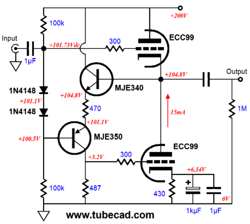
The two diodes almost perfectly compensate for the two transistor voltages drops, making the voltage drop across the top resistor R equal to the top triode's cathode-to-grid voltage. Cool. Very cool. Thus, if the voltage drop across the resistor in between emitters is 2Vdc, then the bottom triode can see a maximum negative grid voltage of -2Vpk; the maximum positive swing can be many times more, but we will run the risk of hitting positive grid voltage. Okay, let's fill the part values and add the missing, but altogether essential grid-stopper resistors.
Note how the 470-ohm resistor is not matched with a like-valued resistor, but instead finds a 487-ohm partner. Why? There is a small loss through the two transistors, so the bottom resistor must be made a tad bigger in value. Also note the DC coupling internal to the circuit. Very nice. One way of looking at this topology is that it has effectively made the bottom triode and the two transistors into a single P version of the top triode, much like NPN and PNP transistors and N-channel and P-channel MOSFETs.
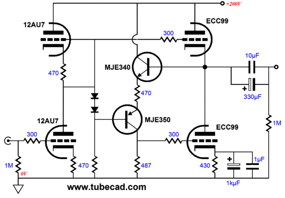
Over/Under Headphone Amplifier
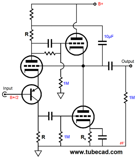
The 12AU7 provides a voltage gain equal to half of its mu, or about 8.5. The ECC99 drives the headphone driver in push-pull fashion, which the two transistors ensure. This headphone amplifier would be a good match for headphones between 32-ohm to 600-ohms. Unlike the Aikido topology, which offers an excellent PSRR figure, this amplifier delivers a relatively poor PSRR of only -6dB. (Looks can be deceiving; just because it looks like an Aikido, doesn't mean it is an Aikido.) This means a well-designed power supply will be needed. Of course, the over/under OTL output stage could be tacked on to the end of an Aikido gain stage, which would bestow the Aikido's stellar PSRR performance on the output to the headphones, as the the over/under topology by itself does offer a fine PSRR. (The Aikido's output could drive the line outs.) With the ECC99, the over/under OTL's output impedance is about 35 ohms.
Over/Under True-Phase-Splitter Variation
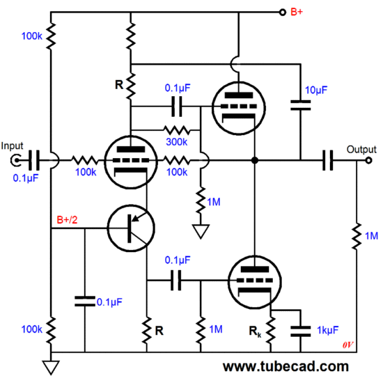
I readily admit that it looks complicated. (Maybe I should have left the internal coupling capacitors out of the schematic.) This circuit is hybrid unity-gain buffer that uses short feedback loop to keep the output in lie with the input. Let's work backwards, once again. We imagine a positive-going pulse applied to the output, which will force the T1's cathode to move more positive to its grid, reducing the triode's current as a result. This pulse will also force the top transistor's base more positive than its emitter, increasing the current flow through this both transistors and the two equal valued resistors, which will develop a positive-going pulse across the bottom resistor, forcing T2 to increase its current conduction. The capacitor that spans the output to the top of the the top resistor, R, relays the positive pulse to the top phase-splitter resistor, which means that the negative-going signal presented tot he the top triode's grid will have 1V subtracted from its peak value. This arrangement ensures balanced current swings from the two output tubes. In other words, the negative pulse at T2's grid will effectively (in terms of cathode-to-grid voltages) equal the positive pulse at the bottom tube's grid, so the two triodes will respond equally to this externally applied pulse. Without this extra capacitor, the top tube would work harder than the bottom tube in opposing the pulse. Okay, maybe with the part values filled out and the operating voltages displayed, it will make more sense.
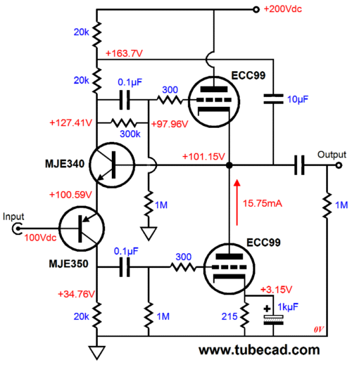
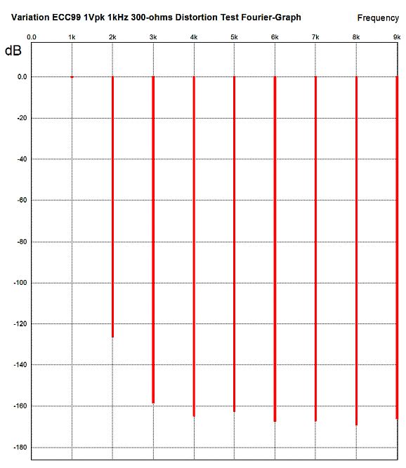
(Note that this array of parts and tube type is only one possible out of a near infinite number of possible configurations. Different transistor types and different tube types, such as the 300B or 6SN7 could be used in this topology.) Note how the transistor-based frontend controls the idle DC voltage split between top and bottom tubes, but the idle current is set by the bottom tube's cathode resistor. How well does this circuit work in SPICE? Superbly well. Here is the Fourier graph for a 300-ohm load at 1Vpk @ 1kHz.
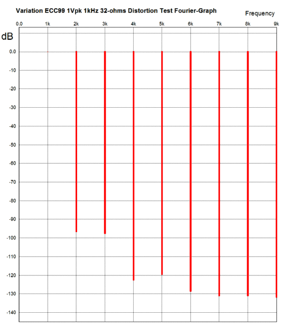
Lovely, isn't? Note the single-ended harmonic structure. Of course, actual mileage may vary. Remember in the world of SPICE, most tube models assume a perfectly constant mu and perfectly matched resistors and perfect voltage sources (power supplies)—all of which reality fails to deliver. Still, relative to other SPICE evaluations, this circuit kicks. With a 32-ohm load, the distortion climbs and the harmonic structure, while still wonderful, looks a bit closer to push-pull.
The measured/simulated output impedance in SPICE came out as less than 0.1 ohms. Not bad for vacuum tubes. The current swing balance between output tubes is stellar. Now imagine a big OTL power amplifier that holds many big tubes, such as the 6C33 or 6AS7 or PL509. With this output-stage topology, the OTL could cleanly drive 8-ohm loads. What would the frontend look like? Need I say it? Aikido. Of course, many more tube-based frontends are useable. But regardless of which is used, no global feedback loop is needed, as the this over/under output stage doesn't need any additional help. No doubt, many readers are turned off by so many solid-state components. So, here is a compromise: 50% fewer solid-state devices.
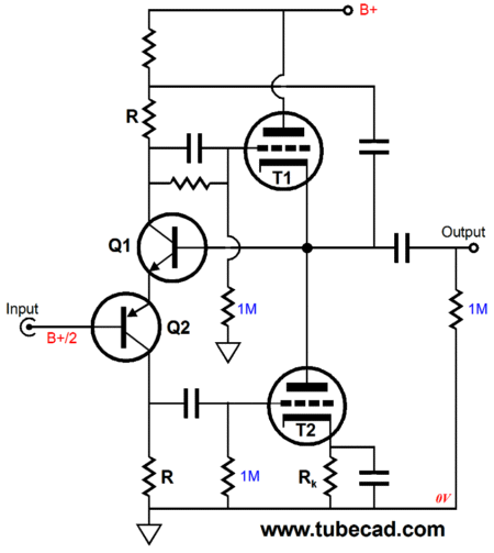
Magic. Now just come up with a cute name. I think that I have it: the Uni-Trans OTL. Okay, back to reality. Note how the PNP transistor receives the input signal. What would happen if the triode above it received it instead? The output would swing in anti-phase, which can be a desirable outcome. The following variation is an inverting unity-gain buffer.
If the input signal swing positive, the input triode will conduct more current, which shall increase the voltage drop across the two phase-splitter resistors (marked R), which will work to turn off the top output tube and further turn on the bottom output tube, swinging the output negatively; the input signal swings negatively, the top output tube increases in conduction, while the bottom tube decreases. The coupling capacitor at the input is needed to provide 100% DC feedback to the input tube, so it can center the DC operating point for the output tubes. An interesting design, no? I can already think of several intriguing variations...but I am over my word limit already.
Next Time
//JRB |
I know that some readers wish to avoid Patreon, so here is a PayPal button instead. Thanks.
John Broskie
E-mail from GlassWare Customers
High-quality, double-sided, extra thick, 2-oz traces, plated-through holes, dual sets of resistor pads and pads for two coupling capacitors. Stereo and mono, octal and 9-pin printed circuit boards available.  Aikido PCBs for as little as $24 http://glass-ware.stores.yahoo.net/
Support the Tube CAD Journal & get an extremely powerful push-pull tube-amplifier simulator for TCJ Push-Pull Calculator
TCJ PPC Version 2 Improvements Rebuilt simulation engine *User definable
Download or CD ROM For more information, please visit our Web site : To purchase, please visit our Yahoo Store: |
|||


| www.tubecad.com Copyright © 1999-2011 GlassWare All Rights Reserved |