| John Broskie's Guide to Tube Circuit Analysis & Design |
| 17 June 2014
PS-SS I am convinced that one (of many reasons) why tube amplifiers so often sound better than their solid-state brothers is that the tube amplifiers hold RC filters or LC filters. These low-pass filters do not eliminate ripple, but they do scrub away harsh higher harmonics. (I have discovered that series voltage regulators also benefit from an RC pre-filter; no doubt, because it gives the regulator less work to do.) As you might expect, I had to include something out of the ordinary on the PS-SS PCB: an RC filter, but with a rectifier shunt.
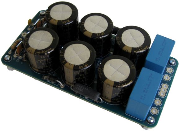
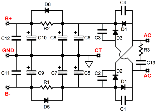
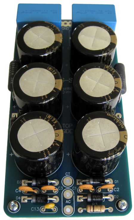
If you look at the above schematic, you will see that resistors R1 & R2 are shunted by rectifiers. What this means is that as long as the current being drawn is less than about 600mA, the RC filter is still in place, filtering away ripple. But once the music makes bigger demands on the power amplifier, the current drawn will go up sufficiently to engage the shunting rectifiers, as their forward-bias voltage will have been reached; now, the RC filter falls out of the circuit and all the rail reservoir capacitors are in parallel with each other, bringing each rail's capacitance up to 9,900µF. If the shunting rectifiers were not there, the rail voltages would sag unacceptably. For example, say 4A of current flows through the 1-ohm RC resistor, then 4V of voltage drop will result, robbing the power amplifier of needed rail voltage, just when it needs it most. But with the shunting rectifiers in place, only 0.6V is lost. In other words, this is something like eating and keeping your cake. The idea is based on the old technique of using a swinging choke in tube-amplifier power supplies, where an LC filter used an easily saturatable choke that would would present high inductance at idle, eliminating hum and reducing the B+ voltage; but as the power amplifier pulled more current, the choke would saturate, becoming just a piece of wire, causing the B+ voltage to rise. Most transistor-based power amplifiers draw between 50mA to 100mA of idle current. For example, the famous LM3886 draws about 50mA. MOSFET-based power amplifiers, in contrast, usually draw between 100mA to 200mA of idle current per channel. So, with two power amplifiers drawing a total of 400mA, only 0.4V of rail voltage will be lost due to the RC filter, which comprises a 1-ohm power resistor and a 3.3kµF, giving rise to low-pass filter with a -3dB frequency of 48Hz. More details. On this six by three inch, extra thick (0.094), 2oz-copper traces, USA-made PCB resides low-voltage, bipolar power supply, including the rectifiers and six power-supply reservoir capacitors, Nichicon audio-grade, 50V, 3.3kµF electrolytic capacitors. Resistor R3 and capacitor C13 shunt the power transformer secondary, so RFI can be converted into heat by the resistor. Each rectifier in the full-wave bridge is shunted by a ceramic capacitor, which helps prevent the generation of RFI. All the rectifiers are MUR410G devices, which are ultrafast types, with a 25nS recovery time, which were designed for use in switching power supplies, inverters and as free wheeling diodes. The PS-SS kit can be used with center-tapped power transformers with up to 32V-0V-32V secondaries, which would develop ±44Vdc rail voltages. A 22V-0V-22V secondary would develop ±30Vdc rail voltages.
The complete PS-SS kit, which includes all the parts needed to populate the PCB and four sets of standoff with screws and O-rings, is available now at the GlassWare-Yahoo store.
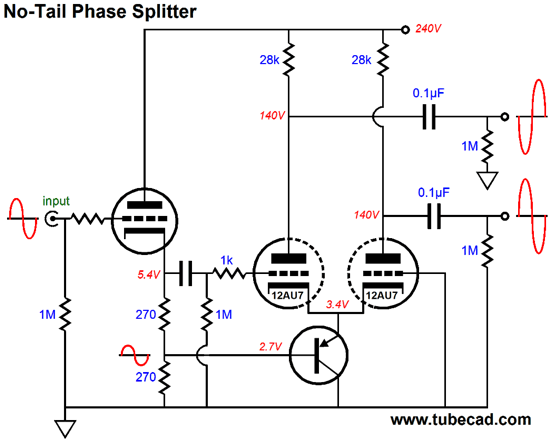
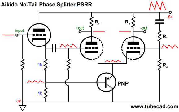
No-Tail Phase Splitters
What bothered me was the grounded grid on the right 12AU7 triode. Shouldn't be doing something more, such as establishing better balance between the two outputs or improving the circuits PSRR? Twenty seconds later, I had sketched out the following schematic.
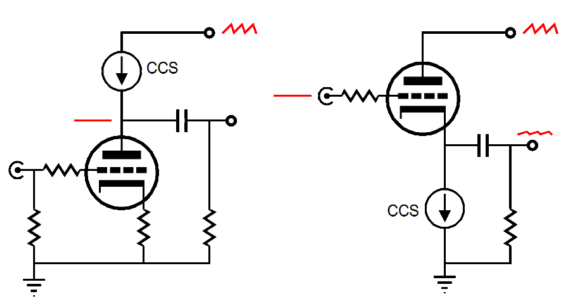
The cathode follower, as everyone knows, is buffer circuit, which provides near-unity gain, low distortion, and a low output impedance. Many also know, unfortunately falsely, that the cathode follower exhibits stellar PSRR. Sometimes they do; usually, they don't. The higher the triode's mu, the better the PSRR; the lower the cathode resistor value, the better the PSRR. This last point is somewhat paradoxical, as it is the inverse of our experience with grounded-cathode amplifiers, where the higher the plate resistor value, the better the PSRR; indeed, with a constant-current source plate load, the PSRR nears infinity.
Why the difference? The triode's plate also can control the flow of current through the triode, being 1/mu as effective as the grid by definition. So, when the cathode follower's cathode resistor is replaced by a constant-current source, the power-supply noise gets divided by the triode's mu. A 6AS7 triode, with a mu of only 2, will leak 50% of the power-supply noise at its cathode, with a constant-current source cathode load. On the other hand, a 12AX7, with its mu of 100, will leak only 1%, a PSRR of -40dB, which is excellent. Alas, the 12AX7 cannot conduct much current; in contrast, triodes that can draw a heavy current flow, such as the 6BL7, 6BX7, 6H30, 12AU7, 12BH7, 5687, ECC99 are usually relatively low-mu types.
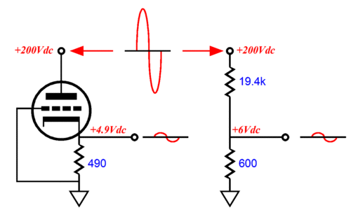
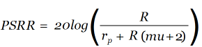
Above, we see a 6SN7-based cathode follower and the equivalent two-resistor voltage divider that yields the same amount of leaked power-supply noise. The cathode follower's formula for its PSRR is given below.
What this means is that the triode-based cathode follower will leak some of the power-supply noise to the phase splitter's input and 50% will be delivered to the cathodes. If we carefully select the two-resistor voltage divider's resistor values, we can null the noise at the phase splitter's outputs.
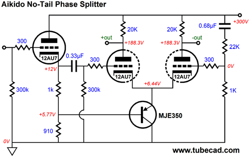
It didn't take long for me to run some SPICE simulations that yielded the following part values for an excellent PSRR figure.
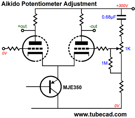
Of course, different tubes will require different values. In fact, the same tubes may require different values over time, as the tubes age or different brands are used. The workaround is to use a potentiometer, so hand-tuned power-supply-noise null can be achieved.
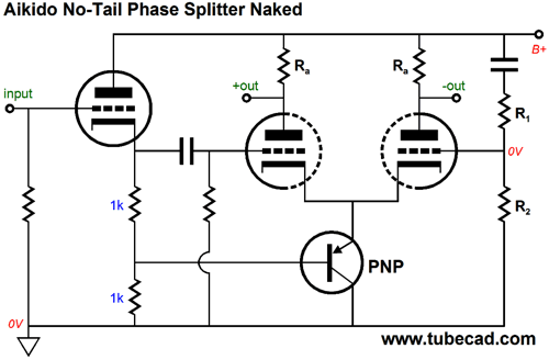
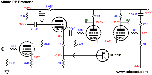
No doubt, many are troubled by my inclusion of the 1M resistor at the potentiometer's wiper. It is there because I do not trust potentiometers, knowing that their wipers often lose contact. With the 1M resistor in place, a path to ground is always maintained. Okay, let's now complete this push-pull amplifier frontend.
Where to start? I chose the MJE350 PNP transistor only because I own a bunch of them. It is a high-voltage transistor, which could be replaced by a lower-voltage device. The gain of this frontend is a little over 50, or +34dB, easily enough to drive KT88 output tubes to full output with no negative feedback, or EL84 tubes with negative feedback. The differential distortion at 50Vpk (100Vpk-pk) was just below 1%; at 1Vpk, it was insanely low in SPICE simulations, about 0.01%, with a lovely single-ended harmonic structure. Of course, the output stage will add its own distortion, which is likely to predominate. Note the 1k and 910-ohm cathode resistor on the cathode follower stage. These values delivered the best balance from the phase splitter. Of course, different tubes and higher or lower B+ voltages could be used, as long as the math makes sense.
Next Time
For those of you who still have old computers running Windows XP (32-bit) or any other Windows 32-bit OS, I have setup the download availability of my old old standards: Tube CAD, SE Amp CAD, and Audio Gadgets. The downloads are at the GlassWare-Yahoo store and the price is only $9.95 for each program. http://glass-ware.stores.yahoo.net/adsoffromgla.html So many have asked that I had to do it. WARNING: THESE THREE PROGRAMS WILL NOT RUN UNDER VISTA 64-Bit or WINDOWS 7 & 8 or any other 64-bit OS. I do plan on remaking all of these programs into 64-bit versions, but it will be a huge ordeal, as programming requires vast chunks of noise-free time, something very rare with children running about. Ideally, I would love to come out with versions that run on iPads and Android-OS tablets.
//JRB |
I know that some readers wish to avoid Patreon, so here is a PayPal button instead. Thanks. John Broskie
Kit User Guide PDFs
E-mail from GlassWare Customers
High-quality, double-sided, extra thick, 2-oz traces, plated-through holes, dual sets of resistor pads and pads for two coupling capacitors. Stereo and mono, octal and 9-pin printed circuit boards available.  Aikido PCBs for as little as $24 http://glass-ware.stores.yahoo.net/
Support the Tube CAD Journal & get an extremely powerful push-pull tube-amplifier simulator for TCJ Push-Pull Calculator
TCJ PPC Version 2 Improvements Rebuilt simulation engine *User definable
Download or CD ROM For more information, please visit our Web site : To purchase, please visit our Yahoo Store: |
|||


| www.tubecad.com Copyright © 1999-2014 GlassWare All Rights Reserved |