| John Broskie's Guide to Tube Circuit Analysis & Design |
20 September 2018 Post Number 439
Autoformer Math
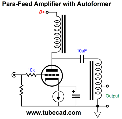
Nonetheless, the autoformer's wider bandwidth and lower distortion ensures that they will not be forgotten. For example, I am stunned that MC step-up autoformers are not more popular; and that midrange and tweeter step-down autoformers that would take the place of L-pads and two-resistor attenuators are not made. In fact, if you want to think way outside the conventional box, here is an idea for you. If you have ever played with tweeters, you might have noticed that many tweeters are sold in two impedances, 8 and 4 ohms. Invariably, in my experience, the 4-ohm version sounds better, sounding snappier and more extended. The reason is revealed the spec-sheets, as the 4-ohm version holds less mass, as it holds less wire. Well, what if we made 1-ohm (or even lower impedance) tweeter and used an autoformer to reflect an 8-ohm impedance to the power amplifier? Since crossover capacitors would still be needed, the autoformer need not hold an air-gap, as no sustained DC current flow could occur. (The autoformer would have to be housed in a magnetically shielded box, however, as it might otherwise pickup harmful hum from the house wiring.) Another project that I would love to see developed would be a para-feed power amplifier with an autoformer in place of an output transformer. Such an autoformer would be much less heavy as a comparable output transformer, as the autoformer passes more power more easily, as the current that enters the autoformer is the same current that flows into the loudspeaker.
Since we are not trying to extract every last watt, we can use a complient-constant-current source (CCCS) in place o fhte choke load.
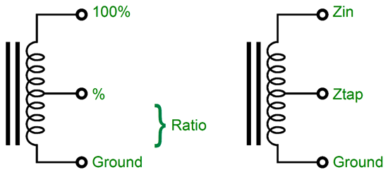
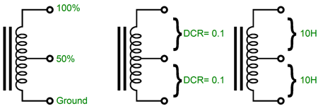
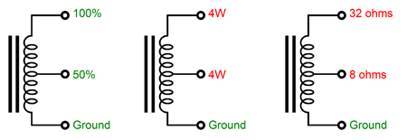
No matter what the audio project, we need to know the math behind the autoformer's winding ratios. The simplest autoformer holds just a center tap at exactly 50% of the single winding, much like a center-tapped choke.
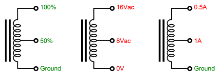
The inductance and DC resistance measured from the ground tap to the center tap equals the inductance and DC resistance measured from the input tap to the center tap. As a result of this 50% division of turns of wire about the core, the output AC voltage measured from the center tap to the ground tap will be 50% of what is presented to the input tap and ground.
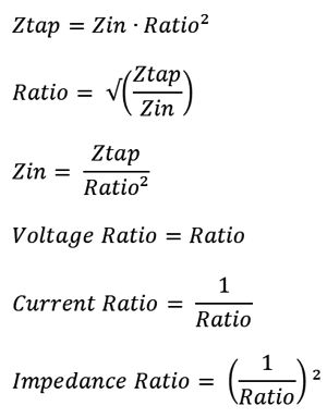
The impedance ratio is equal to the winding ratio of the output tap squared. In this example, 50% equals 0.5, which squared equals 0.25, so the impedance ratio is equal to 1:0.25 or 4:1. Thus, the 8-ohm load appears four times greater at the top of the autoformer, i.e. 32 ohms. Here is the complete list of autoformer formulas.
I mentioned a para-feed single-ended amplifier that held an output autoformer instead of an output transformer. Well, let's quickly design a simple headphone amplifier based on this design premise. We assume 32-ohm headphones and we wish to increase the 32 ohms by tenfold (3,200 ohms) at the end of the autoformer. The first step is to find the winding ratio of the output tap relative to the autoformer's entire single winding. We plug the two impedances into the formula for finding the tap ratio and we get 0.1 or 10%. To make such an autoformer we could simply wind one layer on a coil form and take the tap output at the end of the single winding; then, we would continue laying down nine layers of windings. If the inductance proved insufficient, we might have to lay down 20 layers and take the output tap at the end of the second layer. In addition, much will depend on the core material used.
Which output tube should we use? Well, working on the 2rp rule, wherein the the plate load should equal twice the output tube's plate resistance, we would need a 1600-ohm rp output triode. A 6BL7 triode or a triode-connected 807 would work. But I would use two 6DJ8 triodes in parallel instead. Why? They could run on a lower B+ voltage and the two in parallel would offer much greater transconductance, about 20mA/V; In addition, at 10mA of current flow, the 6DJ8's plate resistance is close to 3200 ohms.
Note that each 6DJ8 triode gets its own cathode resistor and bypass capacitor. Each triode idles at 10mA, which combined equals 20mA, which is the peak symmetrical output current swing at the parallel plates into a load impedance of zero ohms. The peak asymmetrical current swing down is more. With a load of 3,200 ohms, the peak current swing is equal to B+/(Rload + rp) or 100V/(3200 + 1500 or 21.3mA. Since the autoformer's winding ratio is 10, the current ratio equals 10. In other words, the output tap will see +/-200mA current swings, which, against the 32-ohm headphone, will result in 6.4Vpk of peak voltage swing, which in turn equals 640mW. How much inductance is required? With a Zin of 3,200 ohms, my quick calculation reveals that at least 25H are needed, as measured from one end of the autoformer to the other end. L = Resistance/2¶ Frequency The 10µF output coupling capacitor is a tad large in value, as a 3µF capacitor would probably prove adequate. The B+ voltage need not be regulated, as the inductor shields the plates from the power-supply noise. Nonetheless, I would use a well-filtered power supply. Why? Headphones reveal what loudspeakers hide. For example, I cannot bear to hear music with headphones when they attach to my laptop's headphone jack. Painfully bad. But when I plug in an external power amplifier and listen to loudspeakers, it's not nearly as bad. True, the power amplifier's input impedance is much higher than the headphone impedance. Still, the same cheap DAC and output OpAmp are in the signal path. (By the way, I have been using my new Sony Walkman NW-A45 Hi-Res 16GB MP3 Player as a USB DAC with my laptop and the results are wonderful. The Sony player even offers an option of NOT recharging its internal battery while working in this function, so the player's internal battery will power the DAC.)
More Super-Triode Ideas
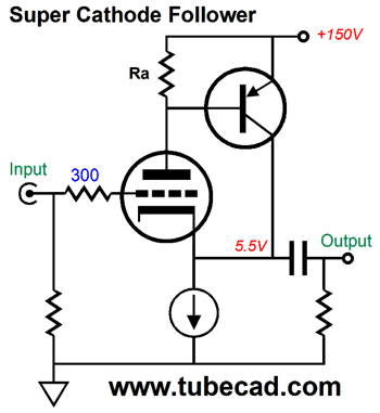
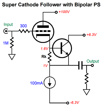
The high-voltage PNP transistor monitors the current flow through the triode via resistor Ra and the transistor strives to maintain a fixed current flow through the triode. The constant-current source loading sets the idle current through both the triode and the transistor. The result is the the triode's relatively weak transconductance becomes supercharged by the PNP transistor. This variation allows us the most voltage for the constant-current source. On the other hand, if big output voltages are not needed, we could use this variation.
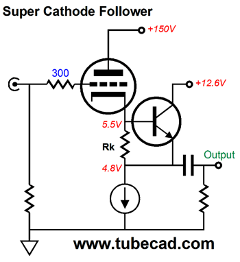
Note how the NPN transistor gets its own B+ voltage of 12.6Vdc, which can also be used to power the triode's heater element.
Note the lower bipolar power supply voltages of only +/-6.3Vdc and the lower B+ voltage for the triode and its cathode voltage. Okay, now that we are warmed up, let's move on to the super-triode SRPP circuit from the last post.
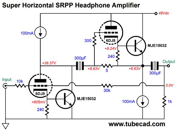
This is not your father's SRPP. There so much going here that I will only point a few highlights; for example, a negative feedback loop sets a fixed (lower) gain and lower output impedance and distortion figure; the B+ voltage relatively low, being only 100Vdc; and the NPN and PNP transistors do the heavy lifting. There is a lot to like here, but my original goal was a far lower B+ voltage. Just the other day, the solution came to mind: a super-triode, horizontal SRPP amplifier.
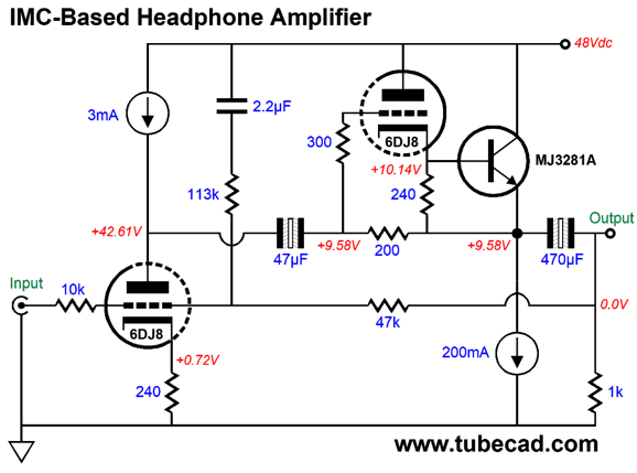
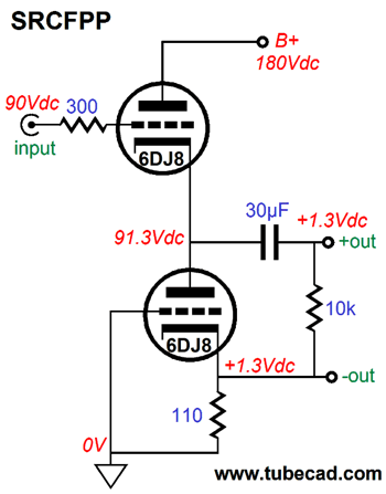
When I wrote my last post, this super-triode SRPP circuit hovered and lingered in my mind. So why didn't I include it that post? I could only apprehend it dimly. Every time the topology flitted into my mind's eye, I would dismiss it, as I couldn't see how the large-valued internal coupling capacitor could attach. Now, it is obvious to me that it should be right there, between the 5-ohm current sense resistor and the input triode's plate. (Yes, I know that they don't make 5-ohm resistors, but they do make 10-ohm resistors, so two could be placed in parallel, yielding 5 ohms.) I have argued here before that when trying to understand the SRPP workings, it is best to pretty much ignore the bottom triode and focus on the top triode, which is effectively a simple impedance multiplier circuit (IMC), which make the external load appear twice as large in resistance than it actually is, so that the two triodes can deliver twice the idle current into the load impedance. Well, what if move even further in the impedance multiplication, so much so that we can replace the first 100mA constant-current source (CCS) with a 3mA CCS.
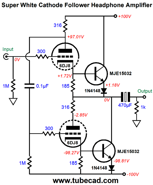
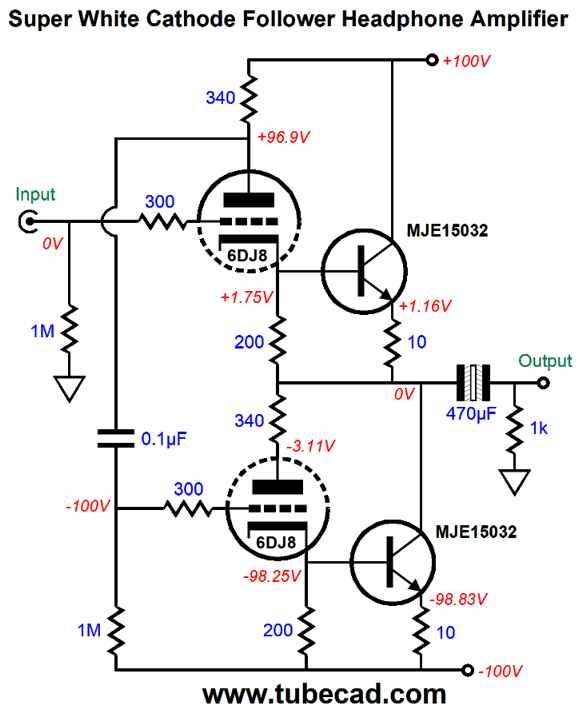
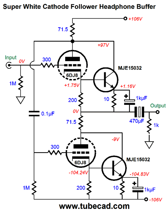
Note the 3mA and 200mA constant-current sources and the 200-ohm current sense resistor, not a 5-ohm resistor. The impedance multiplier circuit makes a low headphone impedance appear vastly larger to the input stage, which explains why the 300µF internal coupling capacitor was replaced by a mere 47µF capacitor. Three topologies rely on a current sense resistor to generate the needed anti-phase signal to drive the slave triode in a push-pull fashion. I label this group of three The Lazy Push-Pull Stages. The SRPP is one of the three. The other two are the White cathode follower and the SRCFPP. In the White cathode follower, the sense resistor is moved up to the top of the circuit, where it reveals the current variation through the top triode. .
What makes this circuit interesting is that top NPN transistor's collector does not terminate into the top triode's plate, which allows us to use a much larger valued current-sense resistor. In addition, the NPN transistors see a series diode at their emitters. The 1N4148 is not a power rectifier, but a high-frequency signal diode. Unlike a 1N4001 rectifier, the 1N4148 diode exhibits a large effective series resistance. In other words, it acts more like a rectifier-resistor hybrid. I wanted some resistance in the emitter circuit, as I feared the transistors over heating due to thermal runaway. (There are no constant-current sources in this topology to slam the brakes on the transistor's current draw.)
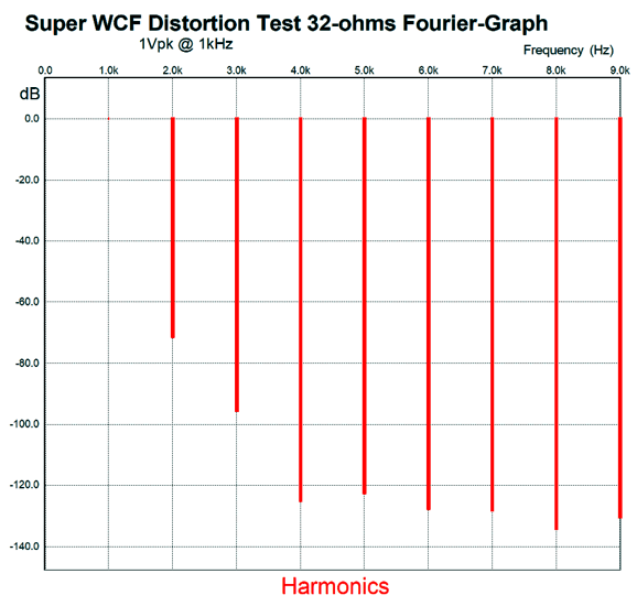
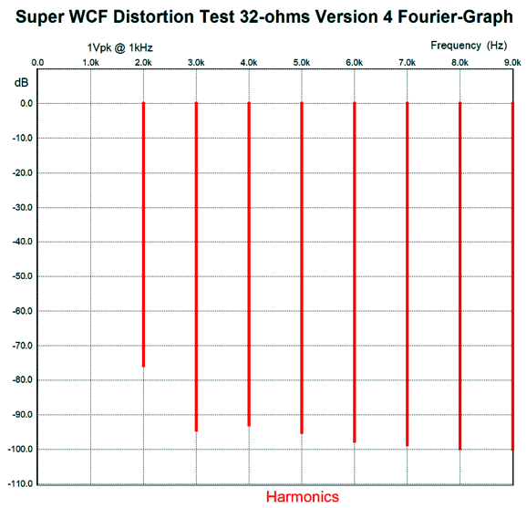
In SPICE simulations, this circuit worked quite well. Here is the SPICE-generated Fourier graph.
The THD comes in at below 0.1% and the harmonic structure is quite single-ended in appearance. Much like most SRPP circuits, the PSRR is weak, but the output impedance is lower, coming in at a little less than 500 ohms. Still, I wasn't pleased enough by this version, so I tried the next one.
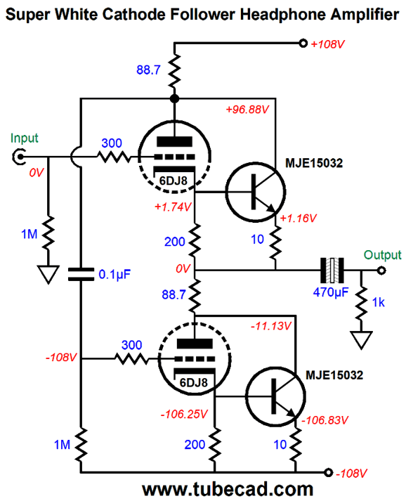
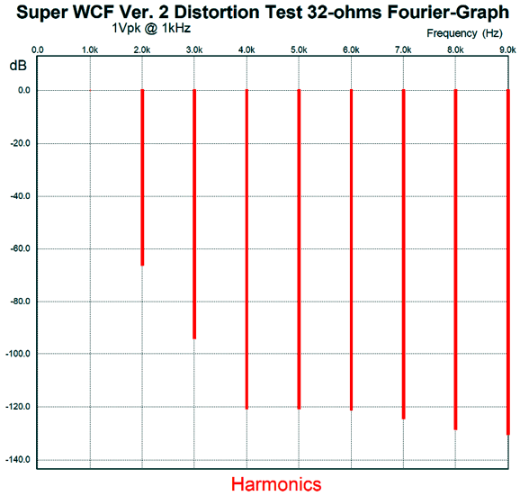
Note that I had to increase the rail voltages to +/-108Vdc to get the idle current up to the previous version's. Here is the Fourier graph.
My next move was to add a capacitor bypass to the two emitter resistors.
Note the change in the sense resistor value and the decrease in rail voltages. (All the White cathode follower circuits have held a 9mA idle current flow for the triode and 116mA for the transistors; a 6DJ8 was also used throughout.) In SPICE simulations, the THD dropped, but the higher harmonics went up.
Which version would sound best? Hard to say. This last version sports a 40-ohm output impedance, which will make some headphones sound better; others, worse. The last of the three The Lazy Push-Pull Stages is the SRCFPP.
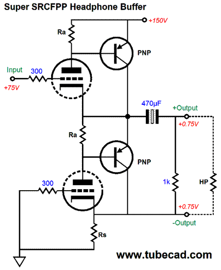
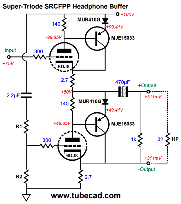
The current-sense resistor is located at the bottom triode's cathode and ground. If more current flows through this resistor, the bottom triode decreases its current conduction, as it effectively sees a more negative grid voltage relative to its cathode. Conversely, if the resistor sees less current flow, the bottom triode increases its current conduction. Making this circuit a super-triode circuit requires adding two PNP transistors.
The transistors will strive to maintain a constant current flow through the triodes. Let's now flesh out the design with some part values.
Yes, there is a lot more now. I added the MUR410G rectifiers and resistors R1 & R2, which allows us to perform an Aikido-mojo PSRR enhancement. In SPICE simulations of this circuit, the balance between top and bottom sections was excellent. Here is the graph of the transistor current swings.
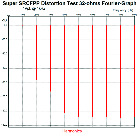
The bottom is a tad weaker than the top, but 2.8-ohms was too much. Yes, it is that tweaky. In fact, this circuit scares me, as the MUR410G rectifiers exhibit a very low series resistance and the only thing that keeps the transistors from running away with themselves are the two 2.7-ohm resistors. But at the same time, we get some fine performance. Here is the SPICE-generated Fourier graph fro 1Vpk into 32-ohms at 1kHz.
The THD approaches 0.01% and the output impedance is crazy low, as in 1 ohm. If the signal source is a DAC or any other power-supply-noise-free signal source and if resistor R1's value is 100k and R2's is 1.8k, the PSRR is a superb -60dB.
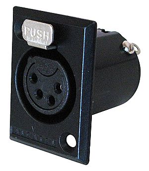
Note that a standard three-connector headphone jack cannot be used with this super buffer, as each channel's output is balanced. Thus, a four-pin jack must be used.
Music Recommendation: More Piano Music While listening to a Tim Ferriss podcast, wherein he interviews Scott Belsky, I heard Belsky mention Carly Comando's piano music, which he used to reward himself when he needed to dangle a carrot in front of himself. I found Scot to be bright and sagacious, so I searched for her music on Tidal. Happily, Tidal offers two albums and several singles from her.
I preferred her One Take album, but it is not as well recorded as her Dreamlife album. If you like Max Richter, then you will probably like Carly Comando. Be sure to check out her piece Everyday on a grand piano.
In fact, if you listen to it first, you will be a lifelong fan of hers. (I wish that the German recording label ECM would pick her up and release more albums by her, as ECM delivers sonic excellence.) I discovered Tigran Hamasyan, the Armenian-born American jazz pianist, a few years ago and rediscovered him recently. His compositions straddle jazz and classical music—with a dash of New-Age whimsy thrown in. Tidal offers at least eight of his albums (with Tidal, you can never be sure what's hidden), three of them in MQA. Give his An Ancient Observer albums a listen. Although certainly piano centric, it's not a solo piano recording, as voices and other instrument appear throughout.
His Luys i Luso (Light from the Light) album definitely falls into the classical category. It is an ECM recording of his explorations of Armenian sacred music and it should be on your short list of music to check out.
When I need a mood uplift, however, I reach for an old favorite of mine: Alicia de Larrocha performing Enrique Grandos' Danzas Españolas. Recorded in 1982, this London CD sounds great and the music is altogether charming. (I used to know a New-Age pianist. I liked his music, but I found it a tad too flaccid, so I forced this CD on him, telling him to listen to it at least two or three times, so it could drip into his unconscious mind.)
By the way, Enrique Grandos claimed to have composed all 12 pieces when he was just 16. He was certainly a child prodigy. Born in Spain in 1867, he later studied music in France with fellow student Maurice Ravel. //JRB
If you enjoyed reading this post from me, then you might consider becoming one of my patrons at Patreon.com
User Guides for GlassWare Software
For those of you who still have old computers running Windows XP (32-bit) or any other Windows 32-bit OS, I have setup the download availability of my old old standards: Tube CAD, SE Amp CAD, and Audio Gadgets. The downloads are at the GlassWare-Yahoo store and the price is only $9.95 for each program. http://glass-ware.stores.yahoo.net/adsoffromgla.html So many have asked that I had to do it. WARNING: THESE THREE PROGRAMS WILL NOT RUN UNDER VISTA 64-Bit or WINDOWS 7 & 8 or any other 64-bit OS. I do plan on remaking all of these programs into 64-bit versions, but it will be a huge ordeal, as programming requires vast chunks of noise-free time, something very rare with children running about. Ideally, I would love to come out with versions that run on iPads and Android-OS tablets. //JRB |
John Gives
Special Thanks to the Special 67
I am truly stunned and appreciative of their support. In addition I want to thank
All of your support makes a big difference. I would love to arrive at the point where creating my posts was my top priority of the day, not something that I have to steal time from other obligations to do. The more support I get, the higher up these posts move up in deserving attention. Only those who have produced a technical white paper or written an article on electronics know just how much time and effort is required to produce one of my posts, as novel circuits must be created, SPICE simulations must be run, schematics must be drawn, and thousands of words must be written.
If you have been reading my posts, you know that my lifetime goal is reaching post number one thousand. I have 561 more to go. My second goal is to gather 1,000 patrons. I have 933 patrons to go. Help me get there.
Support the Tube CAD Journal & get an extremely powerful push-pull tube-amplifier simulator for TCJ Push-Pull Calculator
TCJ PPC Version 2 Improvements Rebuilt simulation engine *User definable
Download or CD ROM For more information, please visit our Web site : To purchase, please visit our Yahoo Store: |
|||


| www.tubecad.com Copyright © 1999-2018 GlassWare All Rights Reserved |