| John Broskie's Guide to Tube Circuit Analysis & Design |
|
05 August 2019 Post 473
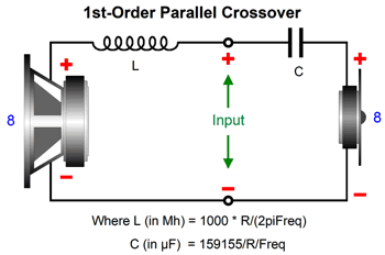
Loudspeaker Crossovers With a loudspeaker's passive crossover we want a flat frequency response and impedance and phase plots and steep crossover slopes. The first three are provided by the first-order crossover, but its slopes only moderately fall away, just -6dB-per-octave, -20dB-per decade.
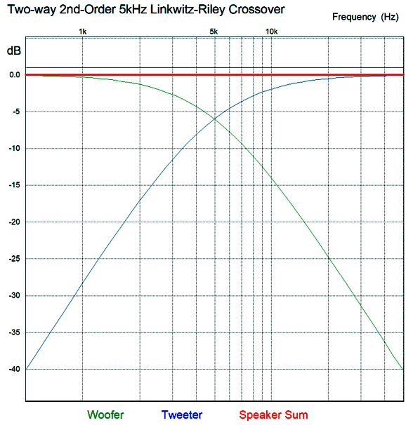
The Linkwitz-Riley second-order crossover, being a second-order crossover, provides twice as steep slopes and an equally flat frequency plot, but presents a hugely peaky impedance plot and poor phase preservation. (See my workaround to this crossover's non-flat impedance in post 403.)
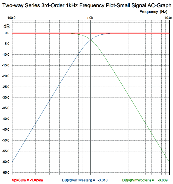
The third-order Butterworth crossover offers both a flat frequency response and impedance plot, but completely fails at delivering flat phase.
Using active crossovers eliminates the problem of having to maintain a flat impedance plot, but we still face the dilemma of having to choose between flat phase and steep slopes; we can't have both. On the other hand, if the loudspeaker holds more than one crossover frequency, we can cascade passive first-order crossovers to favor either the low-frequency or high-frequency drivers with progressively steeper slopes. In other words, we can either prevent the big, heavy, slow woofer from muddying up the midrange or further protect the delicate tweeter from the pounding bass frequencies. Most would opt for protecting the tweeter, as few things are as disheartening as seeing a perfectly round smoke-ring emerge from a toasted tweeter voice-coil.
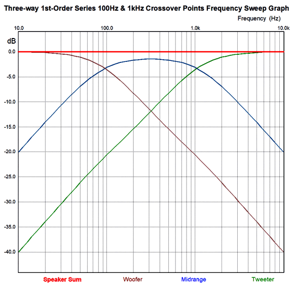
This cascading four-way first-order crossover presents a -6dB-per-octave slope to the tweeter below 3kHz, then a -12dB-per-octave slope below 550Hz, and -18dB-per-octave slope below 100Hz. These two crossovers result in flat phase response along with flat frequency response.
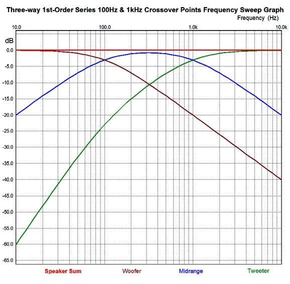
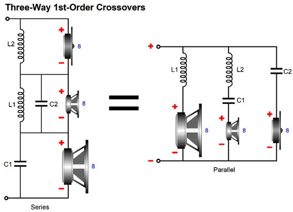
In contrast the following first-order crossover offers no cascading slopes to any of the drivers.
Each driver sees the same -6dB-per-octave slope, which means that the woofer will sully the midrange and that the tweeter might give up the smoke-ring.
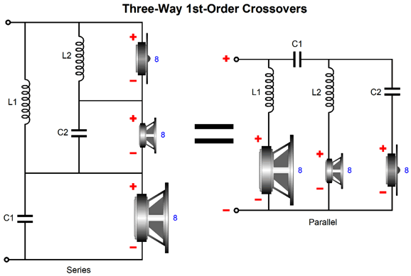
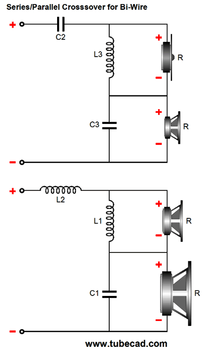
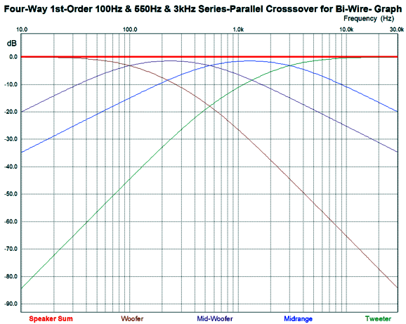
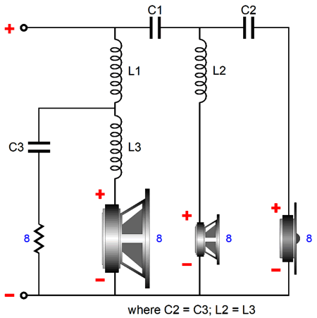
Each driver sees the same crossover slope of -20dB per octave. Raising the tweeter's crossover to 6kHz or higher would help, but this would make greater demands on the midrange driver. Another possible arrangement was shown in post 403, which revealed a bi-wire first-order, four-way crossover that offered cascading slopes to both the woofer and the tweeter, while the mid-woofer and midrange saw -6dB-per-octave slopes at both their crossover frequencies.
Of course, you don't have to bi-wire if you don't want to, as both crossovers could be placed in parallel within the loudspeaker enclosure. In either case, the frequency plots are the same.
I quite like this arrangement, as we could use the same driver for the mid-woofer and midrange, which would help ensure phase relationships between the two drivers and probably deliver a more seamless midrange. Imagine crossover frequencies of 200Hz, 800Hz, and 3.2kHz, with a 10-inch woofer and two 5-inch full-range drivers and 1-inch (or ribbon) tweeter. Most of the human voice would be reproduced by the two 5-inch full-range drivers. Or, if we desired a smaller enclosure, we could use a 6-inch woofer and two 3-inch full-range drivers and 1-inch tweeter—but at the cost of less efficiency and reduced maximum SPLs, but with the added advantage of getting to use higher crossover frequencies, say 300Hz, 1200Hz, and 4800Hz. I know that Peerless (and Dayton) makes some fine 3 and 3.5 inch full-range drivers. So far, I haven't said anything new. Something that is new would a three-way crossover that delivered cascading slopes for the woofer and tweeter, but not the midrange. Is such a thing possible? Indeed it is, but it will only offer a flat frequency response and impedance plots but not a pefectly flat phase plot.
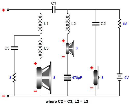
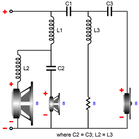
One idea I had was that we could easily add a polarizing voltage to the capacitors in the crossover. The battery, a 9V or 12V type, would last as long as its shelf life, say 5 years or more. The 470µF nonpolarized electrolytic capacitor is only there to trap the DC voltage.
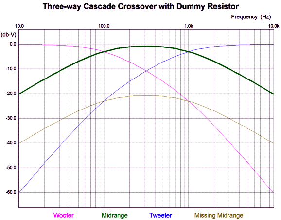
Fundamentally, the idea here is that we cascade the tweeter crossover frequencies and give the woofer an additional crossover frequency. After the large low-frequency inductor (L1), we see a second first-order crossover with the woofer and an 8-ohm resistor. The dummy resistor only gets warm and provides no sound, but it does keep the impedance plot flat. In addition, this setup allows us to use the woofer's own internal series inductance as a feature, as it will become part of the crossover. For example, say that the second inductor (L3) needed to be 0.4mH for a 3200Hz second crossover frequency and that the woofers own Le equaled 0.3mH, and then we would only need to place a 0.1mH inductor in series with the woofer. When we run this new crossover design in SPICE, we discover that the frequency plot is not flat.
What was missing is the sound output from the load 8-ohm resistor. In other words, if we had used an actual second tweeter instead of the load resistor, the added sound output would yield a flat frequency plot. Well, why not use an additional tweeter? Asides from the added expense, the second tweeter would have to cover the same band of frequencies as the midrange, albeit attenuated by 20dB (1/10 the C voltage). Moreover, it would have to seamlessly blend with the other drivers which would prove difficult with the short high-frequency wavelengths.
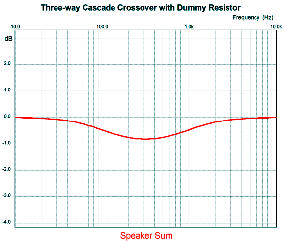
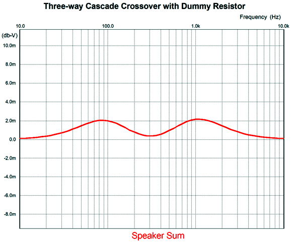
Note how both the midrange and second-tweeter plotlines look the exact same, save for the tweeter's attenuation. The attenuation relative to the midrange is -20dB, which means that one tenth the signal voltage appears across the second tweeter (or load resistor). Well, what if the midrange offered a slightly greater SPL than the woofer and the first tweeter, say about 0.83dB more? The result would be that the midrange would supply the missing second tweeter's output, undoing the dip in the frequency plot.
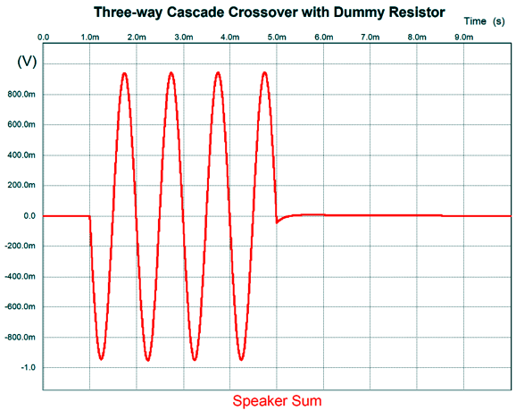
Note that the Y-axis is reading milliBells, not dBs. We are back to flat frequency and impedance plots, but what about the phase plot? Here the midrange's greater SPL did help us, but not enough to make a perfectly clean tone-burst in SPICE simulations.
Not perfect, as the burst does not end at zero. Sure its looks great, far better than any actual loudspeaker in existence, but we must remember that SPICE is assuming speaker drivers that are flat from DC to visible light. Reality will disappoint. Still, this arrangement looks promising and certainly worthy of further research.
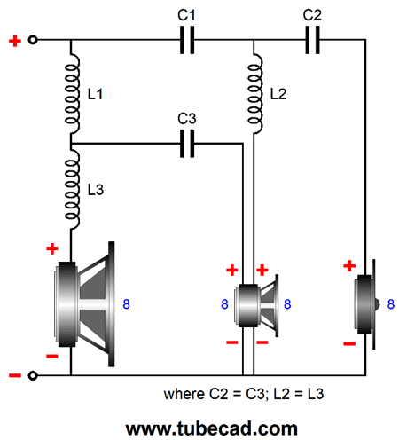
I have a few mental tools that I apply constantly. For example, I like to think in extremes. What if the amplifier's output impedance is zero? What if it is infinity? In general, people hate thinking in extremes. Another mental tool is to invert the situation, the topology, the utterance. For example, Oscar Wilde's famous quip, "There is only one thing in life worse than being talked about, and that is not being talked about," is fairly vacuous as it works just as well inverted, There is only one thing in life worse than not being talked about, and that is being talked about. A truly witty aphorism cannot be inverted without being rendered either nonsensical or plainly wrong. Well, how could we invert this crossover arrangement? We start by cascading the slopes in favor of the woofer, not the tweeter. This way, the woofer sees a first-order slope and then a second-order slope. The next step is to add a cascading crossover frequency to the tweeter.
Whoa! This arrangement requires huge capacitor (C3) and inductor (L3) values for the dummy load resistor. SPICE simulations revealed the results as before. Once again, if the added resistor could put out sound, its output would be identical to the midrange's, albeit attenuated by -20dB. Then it hit me, why not use a midrange with two voice-coils? True, most dual-voice-coil speaker drivers are subwoofers, but smaller drivers are made with two voice-coils, such as the Aurum Cantus AC-180F1D DVC 7-inch driver . This driver holds two 8-ohm voice-coils. DVC stands for dual voice coils.
The best approach would be to use my first arrangement that cascaded the high-pass crossovers, so we could use the smaller valued capacitor and inductor values with the second midrange voice-coil.
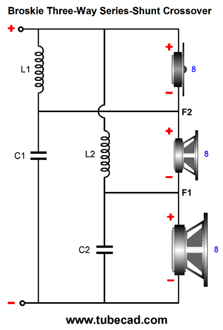
Now for Something Altogether New Well, I like to start a new design by doing exactly the opposite of what everyone else does: by imagining that no existing designs exist, no prior-art topologies, no long-standing traditional approaches. Such an approach allows us to clearly examine our goals and the tools we have available to us. I once knew a brilliant electrical engineer, who has sadly passed on and who had worked at Varian, a huge medical-device company that makes such equipment as proton-therapy systems. He was super senior and super accomplished; his job was to fix stalled projects. His approach to solving problems reminded me a of a computer booting up, as he started with the lowest level possible, which betrayed his having got a BS in physics from UC Berkeley before going on to his masters in EE from Stanford. At first, his approach irked me, as I didn't see why he had to downshift so much, starting at the fundamentals of moving charges. But after watching him fix the unfixable a few times, I realized that his approach worked especially well when you were stuck—besides, his approach actually didn't take all that long to up-shift to higher levels of abstraction. In contrast, those stuck were stuck at the highest level of magnification of the small problem that brought the big project crashing down. I knew what I wanted from the crossover, flat frequency and flat phase and flat impedance, and what tools I had to work with: capacitors, inductors, and resistors. I started with the tweeter and placed a shunting inductor across it and then shunted the woofer with a capacitor. It looked like I was going to recreate the series first-order crossover, but then it hit me. I could ignore the midrange and just concentrate on the woofer and tweeter, both of which had to have cascading crossover slopes. In less than 10 minutes, I had drawn the schematic and found all the part values. It looked crazy, but conceptually it made perfect sense. (Well, at least it did to me.) I had to wait a painful ten hours before I had a chance to run SPICE simulations. In those passing ten hours, I had convinced myself that my new crossover wouldn't work, as it was so simple and so obvious and so damn perfect that someone else must have already created it and I would have to know about if it was any good; therefore, it was just another failed attempt, promising much, but delivering nothing useful. I was wrong.
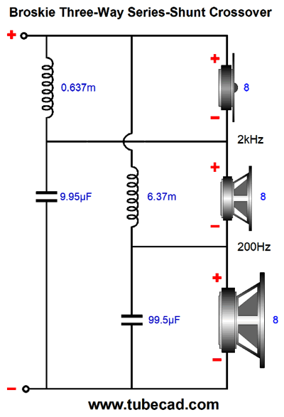
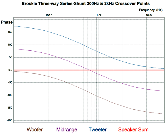
That is it. No bi-wiring is allowed or possible, as all three drivers are in series. Seemingly, the midrange doesn't get any crossover components, but it does; in fact, it gets all the capacitors and inductors. Let's fill in the crossover part values for crossover frequencies of 200Hz and 2kHz, which evenly splits a bandwidth of 20Hz to 20kHz.
The first SPICE simulation revealed an insanely flat frequency plot of the summed output from the three drivers, as in micro-Bells flat.
The second simulation disclosed a phase plot equally flat.
Both these results only made me more nervous, not less, as I had never seen any crossover this good, other than the conventional first-order. The tone-burst simulation showed a flawless series of sine waves.
This looks more like an amplifier's output than any loudspeaker's output. Here are the separate traces for each driver.
The math worked perfectly. Note that the burst stopped dead at 11mS, yet the woofer, midrange, and tweeter still see a signal beyond 11mS, as the reactive devices release their stored energy. Nonetheless, the result sums to a perfect tone burst. The math is simple:
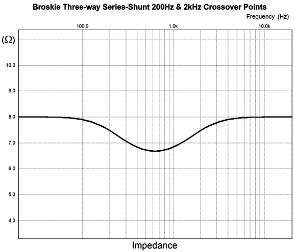
The capacitor values are in µF and the inductor values are in mH. I knew that the last SPICE test would reveal problems, as my math calculations had indicated that the impedance plot would not be flat. It wasn't.
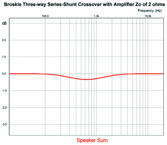
Mind you, the nominal 8 ohms only dips to 6.77 ohms at 316Hz. Still, this means that those who own current-output or feedback-free tube amplifiers need to worry, as the dip in impedance will prompt a midrange dip centered at 316Hz in this example, which will create a 1.6dB dip with a current-output amplifier. We can partially correct this by either using a midrange with slightly higher efficiency or using a woofer and tweeter with slightly lower efficiency. Mind you, this is the absolutely worst case scenario, as a current-output amplifier's output impedance approaches infinity. In addition, few own current-output amplifiers. More likely, if you are reading this, you own a single-ended or OTL power amplifier or a transformer-coupled tube amplifier that runs either low feedback or no feedback, resulting in an output impedance of up to 2 ohms. The 2-ohm output impedance, however, only creates a dip of 0.33dB.
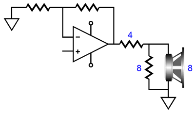
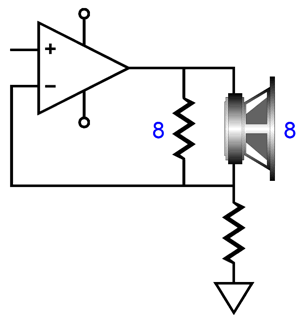
In general, if you own a solid-state amplifier, do not worry about the drop in impedance. By the way, with the exception of ribbon and planar loudspeakers, most dynamic loudspeakers present impedance plots that resemble roller coasters, not ruler edges. One easy workaround would be to use a midrange with an impedance of 10 ohms or use 8-ohm midranges with 6-ohm woofers and tweeters with the current-output amplifier; this not the perfect solution, but it works fairly well. By the way, how do you implement an attenuation of a speaker driver with a current-output amplifier? With a voltage-output amplifier, our goal is to preserve the nominal impedance and produce the require attenuation. For example, a -6dB padding of an 8-ohm tweeter's output is accomplished with the following circuit.
The 8-ohm resistor in parallel with the tweeter's 8 ohms results in a combined resistance of 4 ohms, which is equal to the 4-ohm series resistor's resistance, so the tweeter sees 50% of the amplifier's output voltage swings. With a current-output amplifier, however, we need only place an 8-ohm resistor in parallel with the tweeter.
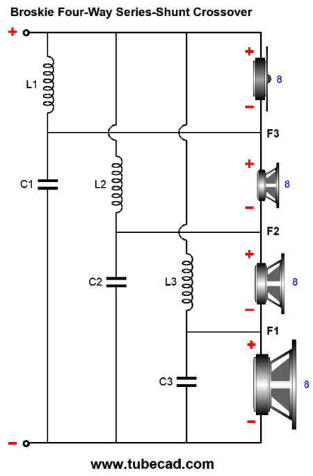
Yes, this arrangement halves the load resistance. But that is okay. Current-output amplifiers are the inverse of voltage-output amplifiers. The best-case-scenario for a voltage-output amplifier is an infinite load impedance; for the current-output amplifier, zero ohms. The worst-case-scenario for a voltage-output amplifier is a dead short to ground; for the current-output amplifier, an open circuit, i.e. infinite load impedance. My new series-shunt crossover is not limited to three-way loudspeakers, as a four-way crossover would be easy enough to create.
Broskie Four and Five Way Series-Shunt Crossovers
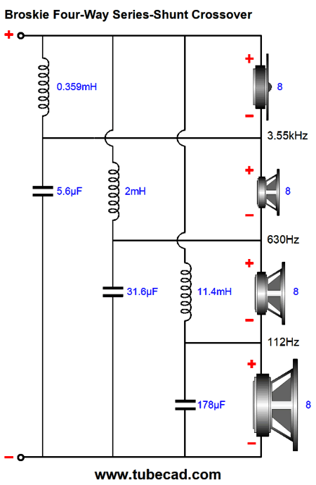
Let's use 112Hz, 630Hz, 3.55kHz as the crossover frequencies, before filling in crossover part values. These three frequencies evenly split up the octaves between 20Hz to 20kHz, so each driver gets an equal load of frequencies.
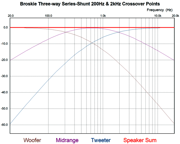
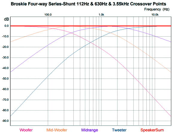
Note that these values are the same as those that would be used in a conventional first-order crossover. The following SPICE simulation display the crossover slopes within a 20Hz to 20kHz bandwidth.
Interesting isn't? Let's start with just the woofer and tweeter. Both initially see a shallow crossover slope; in fact, both are only down 2.5dB at their crossover frequency, not -3dB. But as we move away from the crossover frequency, the slope increases. What happens to the mid-woofer and midrange is equally interesting, as they both see asymmetric slopes. The mid-woofer's crossover slope between it and the woofer is -20dB-per-decade, but -36dB-per-decade between it and the midrange. The midrange flips the slopes, so its crossover slope between it and the mid-woofer is -36dB-per-decade, but -20dB-per-decade between it and the tweeter. Just like the three-way version, the phase and summed frequency plots are flat and tone-bursts come out looking like tone bursts. Here is the required math:
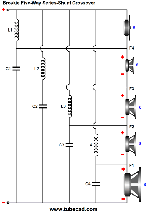
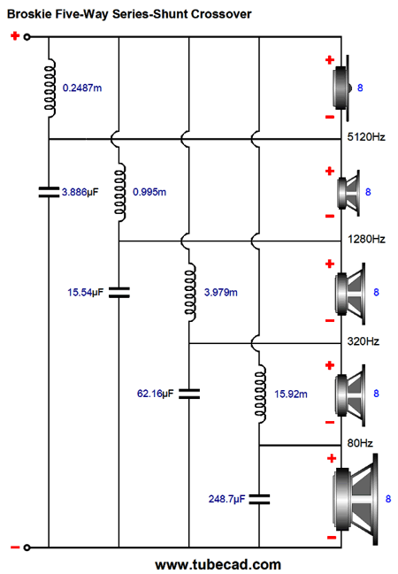
Once again, the capacitor values are in µF and the inductor values are in mH. Although I could show six-way and seven-way…and ten-way versions of my series-shunt crossover, I will stop at the five-way version. (By the way, a ten-way loudspeaker would prove interesting, as each driver would cover only one octave.) Since I wanted to cut up the 20Hz to 20kHz bandwidth into five equal segments, I chose 80Hz, 320Hz, 1280Hz, and 5120Hz crossover frequencies, so each driver covers two octaves.
Note how easy it is to expand the basic topology. Four capacitors and four inductors are needed.
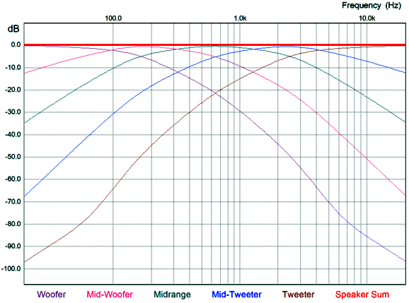
The summed outputs from all five drivers frequency response is dead flat, as is the combined phase response, but the impedance takes a dip.
The frequency plots are attention-grabbing—well, at least to me. The midrange driver is the only one to see symmetrical crossover slopes. Although the high-pass and low-pass slopes are symmetrical, they are not linear, as the slopes deepen as they go away from the center frequency of 630Hz. The midrange, straddling 320Hz to 1280Hz, must reproduce the bulk of the musical content. Both the woofer and tweeter see the same deepening slopes and then they begin to grow less steep, at 80Hz for the tweeter and 5120Hz for the woofer. Nonetheless, this crossover yields flat phase and frequency response and clean pulses.
Nothing is harder for a loudspeaker to reproduce than a tone burst made up of a few positive pulses, as super-wide bandwidth and zero phase shift are needed. Of course, no actual loudspeaker could produce these clean pulses, but we are testing crossovers here, not an actual complete loudspeaker system. In other words, a perfect crossover design is an necessary, but not sufficient cause for a perfect loudspeaker system. Here is what the five drivers must deliver to produce these two perfect pulses.
Since each pulse is 1mS long in duration, it could hold one complete 1kHz sinewave. As we would expect, the midrange fills in most of the pulses. Here is the math:
Once again, the capacitor values are in µF and the inductor values are in mH.
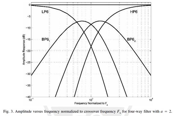
Reality Check Google searches came up empty of anything close to it. Google Patent searches revealed that very few patents have been awarded to speaker crossovers in the last 50 years. And few crossovers patents hold any meat, embarrassingly little. For example, the Patent Office is seemingly happy to grant patents on already established crossover designs. I found at least two patents that claimed to have invented the series crossover. One crossover design that was actually interesting and novel only held inductors, no capacitors, USOO6115475A. Sadly, it suffers from several problems. One patent presented a crossover with two configurations: one for male listeners and one for female listeners, betraying a woeful lack of wokefullness, as everyone knows that a male is a female, if he says so. Shameful, just shameful. One patent held strict ratios between crossover frequencies. Many patents used resistor-damped inductors. One even used common-mode chokes. My hunting in old issues of the JAES (The Journal of the Audio Engineering Society) offered one interesting article titled, Active All-Pass Crossover Networks with Equal Resistors and Equal Capacitors, by Rene´ Christensen. (Vol. 54, No. 1/2, 2006 January/February) Here is a graph from the article.
Christensen wrote in his ending acknowledgement,
Is this the same Dueund of the capacitor fame? I will have to do some searching. In short, until someone sends me some prior art, I am claiming this new crossover design as mine. The next step is to build one three-way speaker using three identical fullrange drivers with the new crossover and compare it to one identical fullrange driver. Why? No speaker driver is perfect. I want to test the crossover, not the drivers. By comparing the single tree-way speaker to a single fullrange I sidestep the driver's frequency response and phase aberrations. In other words, the three-way should sound better than the single fullrange. Why better and not just the same? The three-way should dramatically reduce frequency modulation distortion. Missing from all the crossovers was Zobel networks that undo the driver's own internal inductance, Le. Their omission was to further clarity, but in actual practice they are essential. Another project will be to create an active version of the series-shunt crossover that doesn't use inductors.
Music Recommendation: Tal Wilkenfeld Love Remains It didn't win me over the first time I heard it, but my second listening was not with computer speakers, but my listening-room speakers. I liked it much more and it sounded great. //JRB
User Guides for GlassWare Software
For those of you who still have old computers running Windows XP (32-bit) or any other Windows 32-bit OS, I have setup the download availability of my old old standards: Tube CAD, SE Amp CAD, and Audio Gadgets. The downloads are at the GlassWare-Yahoo store and the price is only $9.95 for each program. http://glass-ware.stores.yahoo.net/adsoffromgla.html So many have asked that I had to do it. WARNING: THESE THREE PROGRAMS WILL NOT RUN UNDER VISTA 64-Bit or WINDOWS 7 & 8 or any other 64-bit OS. I do plan on remaking all of these programs into 64-bit versions, but it will be a huge ordeal, as programming requires vast chunks of noise-free time, something very rare with children running about. Ideally, I would love to come out with versions that run on iPads and Android-OS tablets.
//JRB
|
|
John Gives
Special Thanks to the Special 85
I am truly stunned and appreciative of their support. In addition I want to thank the following patrons:
All of your support makes a big difference. I would love to arrive at the point where creating my posts was my top priority of the day, not something that I have to steal time from other obligations to do. The more support I get, the higher up these posts move up in deserving attention. Only those who have produced a technical white paper or written an article on electronics know just how much time and effort is required to produce one of my posts, as novel circuits must be created, SPICE simulations must be run, schematics must be drawn, and thousands of words must be written. If you have been reading my posts, you know that my lifetime goal is reaching post 1,000. I have 527 more to go. My second goal is to gather 1,000 patrons. I have 915 patrons to go. Help me get there.
Only $12.95 TCJ My-Stock DB
Version 2 Improvements *User definable Download for www.glass-ware.com |
||


| www.tubecad.com Copyright © 1999-2019 GlassWare All Rights Reserved |