| John Broskie's Guide to Tube Circuit Analysis & Design |
| Post 205 24 June 2011
Quick CCDA Overview A line stage is needed either to boast a weak signal voltage sufficient to drive a power amplifier to full output, or to deliver current sufficient to drive a high capacitance load (such as long stretches of interconnect). Just how much gain is needed for a line amplifier? Let's begin the answer with the observation that most line amplifiers have too much gain. (After all, many audiophile run passive line-stage setups, which offer no voltage gain.) While this extra gain impresses the audio neophyte who marvels at the power implicit in the distorted thunder that a mere one quarter twist of the volume knob provokes, it ultimately only subtracts from the useful range of turn on the volume and usually only worsens the signal-to-noise ratio of the line stage. If 20 to 30 dB of gain is too much, how much then is best? The answer will depend on each system. A safe guess, however, would be 6 to 20 dB of gain, which translates into 2 to 10 times the input signal. Calculating the gain from a CCDA amplifier is easy, when the cathode resistor is left un-bypassed, as the gain roughly equals half the mu of the input triode used. For example, the 12B4 presents a mu of 6.5, so the gain will equal about 3 (+9.5dB) at the output, not 3.5 that 6.5/2 implies due to gain loss from the cathode follower. Gain = muRa / (rp + Ra + [mu +1]Rk) And since we wish to split the B+ voltage at the input tube's plate, Ra = rp + (mu + 1)Rk Thus, the gain formula reduces to Gain = muRa / 2Ra which further reduces to Gain = mu/2 Unlike the Aikido circuit, which delivers a perfect platform for tube rolling, as vastly different tubes can be swapped in and out of the board (say a 6AQ8 and 6H30) without having to change the resistor values, the 12B4 CCDA requires more care in selecting resistor values. The problem is the daunting array of different possible B+ voltages and idle currents. For example, a 12B4 CCDA might run a B+ voltage of only 100Vdc or as much as 300Vdc. Moreover, the plate resistor cannot be the little 1/2W devices that the Aikido freely uses, but big 2W (or 3W) power resistors, which are hard to find and expensive. The solution the problem of too many resistor combinations is to let the idle current move, but lock the plate and cathode resistor values. A triode with a cathode and plate resistors acts like a resistor, not a perfect resistor, but a fairly good one.
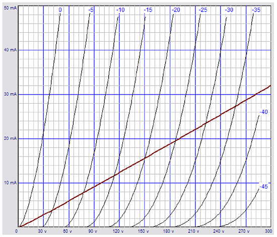
As the graph reveals, a 12B4 triode with a 1000-ohm cathode resistor (no plate resistor) behaves much like a 9.4k resistor. (By the way, note the much improved linearity over the plate curve lines, albeit at the cost of greatly increased plate resistance and reduced transconductance. Adding a plate resistor also makes the triode behave more like a good resistor.) The formula for the effective resistance is: R = rp + Ra +(mu + 1)Rk The upshot is that if we chose plate and cathode resistors values to work at the middle of possible B+ voltages, these same resistors will still split the B+ voltage across a wide range of B+ voltages. In other words, we can use a wide range of B+ voltage with the same cathode and plate resistor values. In general, the following formula is a good starting point: Rk = (Ra – rp) / (mu + 1)
Hybrid Op-Amp
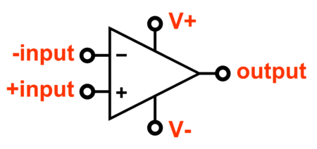
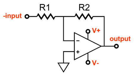
The perfect operational amplifier is easy to define: infinite bandwidth, infinite input impedance, infinitely low output impedance, infinite gain, infinite slew rate, and an input and output voltage swing limits equal to its power supply rail voltages. Well, in point of fact, today’s solid-state Op-Amps come very close to this ideal. Yet, when it comes to high-end audio, the Op-Amp is a marketing liability, as discrete components are seen as the expensive, difficult, and more desirable alternative. Why? Where to begin. As amazing as are modern solid-state Op-Amps, they must by necessity entail compromises in their construction; they are tiny after all. For example, the internal resistors are microscopic and, thus, dissipation limited, as are the transistors. In addition, the internal capacitors are crummy beyond belief. Moreover, because of their small size and because battery-powered applications demand it, they run on embarrassingly low currents, often only a few milliamps, sometimes less than 1mA for the entire Op-Amp; considering that every Op-Amp holds at least three stages, that means that each stage only gets the smallest trickle of current. In sharp contrast, an operational amplifier based on discrete components can be as big and powerful as we desire. We can use 2W resistors and huge Teflon capacitors and massive heatsinks and robust high-voltage power transistors. But we must pay in cost, effort, heat, and cubic inches. And if we wish to jettison all practical constraints, we can build a tube-based Op-Amp. The only problem with an entirely tube-based Op-Amp is that it will prove difficult to design a version for use with a bipolar power supply. (If only there was a P-version of the triode.) The easiest workaround is to design a hybrid OpAmp. I can hear many asking, How many stinky transistors (or MOSFETs) will be needed? Not to worry, just one. Before going any further forward, let's review some Op-Amp basics. The inverting amplifier configuration inverts the input signal's phase so that it is amplified 180° out of phase at the output. In other words, a positive input voltage results in a negative output voltage. The ratio between resistors, R1 & R2, sets the gain of the inverting amplifier. For example, if R1 equals 10k and R2 equals 100k, the resulting gain will be 10; thus, if +1Vdc is presented to the input, -10Vdc will come out at the output.
This is the preferred configuration for an Op-Amp. The rule is: Whenever possible—invert. The advantage the inverting configuration bestows lies in that input signal enters the Op-Amp at a zero voltage, zero impedance point, the conjuncture of the two feedback resistors and the inverting input. This means that unlike the non-inverting amplifier configuration, which must deal with the entire voltage swing of the input signal, which can cause non-linear effects because of the moving of the input bias voltages and compressing of voltage headroom as the input signal swings from one extreme to the other, the non-inverting amplifier inputs are comfortably at the same bipolar power supply midpoint. Also, unlike the non-inverting amplifier, the gain of this amplifier can be set to less than unity, unity, or greater than unity. (Not all IC Op-Amps, however, are unity gain, or close to unity gain, stable. Check the Op-Amp spec sheet for more information.) Now, we can move on to the tube hybrid OpAmp shown below.
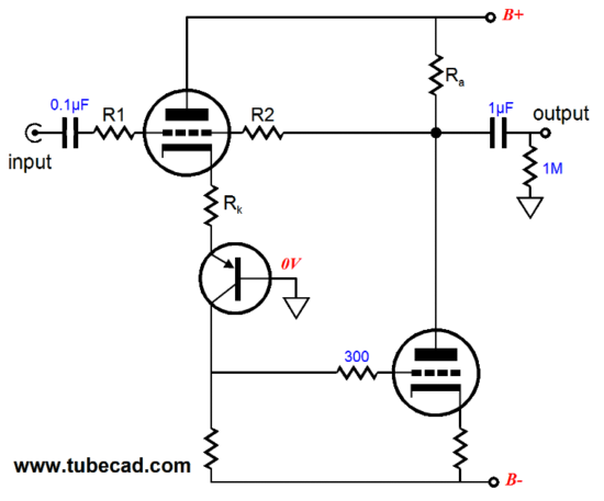
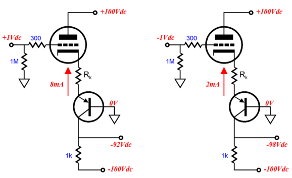
This Op-Amp holds no internal coupling capacitors, being DC coupled throughout; the 1µF coupling capacitor at its output is almost, but not quite, optional. But I am getting ahead of myself. So let us begin at the top triode's grid. If this grid sees a positive input voltage, the triode will increase its current conduction. Because the triode's plate sees a fixed DC voltage, the only element that can move with the input signal is the cathode. Because the cathode resistor is not bypassed, the input signal the grid sees will be superimposed upon the cathode resistor, although attenuated quite a bit. In other words, the triode is configured inside a cascode topology, which will serve to preserve much of its transconductance. For example, if the triode's effective transconductance reduces down from, say, 10mA/V to 3mA/V because of the unbypassed cathode resistor, then a 1Vpk input voltage will prompt a 3mA increase in current conduction; a -1Vpk voltage, a 3mA decrease in current conduction.
Note that the signal developed across the 1k resistor is the result of multiplying the triode's effective transconductance against the resistor's resistance. The larger the resistance, the higher the gain. And, unlike the grounded-cathode amplifier, the resulting gain can easily exceed the mu of the triode. In addition, since the triode's plate is locked tightly in place, the triode cannot develop any dreaded Miller-effect capacitance, ensuring a wide bandwidth. The PNP transistor could easily be replaced by a high-voltage P-channel MOSFET (or FET). So what's not to like? Unfortunately, plenty. But it will have to wait until next time.
Next Time
//JRB |
|
I know that some readers wish to avoid Patreon, so here is a PayPal button instead. Thanks.
John Broskie
E-mail from GlassWare customers:
And
High-quality, double-sided, extra thick, 2-oz traces, plated-through holes, dual sets of resistor pads and pads for two coupling capacitors. Stereo and mono, octal and 9-pin printed circuit boards available.  Aikido PCBs for as little as $20.40 http://glass-ware.stores.yahoo.net/ Only $12.95 TCJ My-Stock DB
Version 2 Improvements *User definable Download or CD ROM www.glass-ware.com |
||


| www.tubecad.com Copyright © 1999-2011 GlassWare All Rights Reserved |