| John Broskie's Guide to Tube Circuit Analysis & Design |
|
21 May 2010 Hasta la Vista, California
Since my last post, life has been more than normally crazy, as I and my family are moving eastwards, abandoning California, and embracing Colorado. Why? As I put almost one year ago,
Moving is never easy; and each successive move gets harder. Thus the absence of any recent posting on my part. Packing, discarding, packing, shipping, planning, fretting, packing, driving, packing…the month of May has both hammered me and shoots pasts me. In this month, I have already made one road trip to Colorado and before the month ends, we will all, family and dog, leave California. No new orders for PCBs or kits can ship until after the first week in June. To make up for the hassle, I have put all the TCJ software downloads on sale.
Since writing about the Tringlotron circuit, I have had an itch to create my own "_tron" topology. The first step was to pick a name, a name that implied three, as I wanted to limit myself to three active devices, just as the Tringlotron does. "Tritron" was a tube brand from the 1930s, so it would not do. After much head scratching, I chose "Triadtron." Surely "Triadtron" is such a cool name that it demands an equally cool topology. Now all I had to do was come up with a new topology. Mind you, this is not how it is supposed to work, you don't come up with a name and then create a new topology to match it. But, of course, that is precisely how much of the stuff that fills our modern life is created, from movies to kitchen appliances; just ask any marketing department. A major principle of marketing is “The right name is an advertisement in itself.” And as Søren Kierkegaard rightly pointed out back in 1846, in his book, The Present Age, "the present age is an age of advertisement." Advertising pervades and saturates the whole of our life. TV shows and movies are sullied with product placements. Web pages flash and blink with inane banners. Public busses and benches are draped in corporate graffiti. My kids can quote TV ads the way a Puritan could quote scripture. Politicians never cease campaigning. Soon, I expect Google to offer free toilet paper, toilet paper completely covered with ads. So, at one extreme, we have George Orwell saying, "Advertising is the rattling of a stick inside a swill bucket;" and at the other, Anton Chekhov telling us that "Advertising is the very essence of democracy." Who is right? Can both be wrong? Or could both be right? My inclination is, as with most things, to agree with Orwell. But at the same time, I must admit that Chekhov has a valid point, for surely, we choose which ad to believe. All cars, toasters, beers... cannot be the best, in spite of what the ads say. And what would high-end audio look like without glossy advertisements, snobby salesman, slick packaging, exotic materials, or astronomic prices? Have you also have noticed that the worst audio products usually get the biggest, slickest ads. Nonetheless, I am reminded of what one of my favorite writers, Milan Kundera, said of business having only two functions: marketing and innovation. I cannot stop doing the latter, but the former requires effort, great effort. A friend once told me that the best thing about the Aikido circuit was—not its low distortion, low output impedance, nor its great PSRR—but its name. At the time, hearing this irked me greatly, as I thought it the least important aspect of the circuit. Today, I better understand what he was saying, for "names are everything."* As they used to say in the Soviet Union and as they say today in feminist studies, what is not named does not exist. Back to circuits. I had not only the desire to create a new circuit, I had the need. Recently, I built and tested a new Aikido PCB, the LV Aikido, which is meant to replace my old 24V Aikido board. The 6GM8 is an amazing little tube and I am quite surprised by just how good this little tube can sound, but the 6GM8/ECC86 tubes have become so rare and so expensive that some other tube must be used. Thus, the "LV Aikido," which stands for low-voltage Aikido, as this board could be used with either a B+ of 24Vdc with 6GM8 type tubes or 48Vdc with ECC99 or 12BH7 tubes. (No, it is not for sale yet, as I have much to finnish first. But soon...)
The PCB is small, only 3.6 by 5.5 inches. And it fits nicely in an extruded enclosure, such as the one made by Hammond.
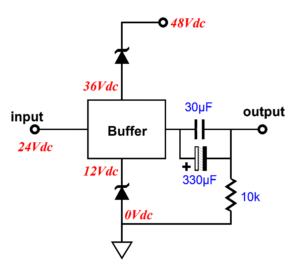
Cute, mega cute. And sweet, very sweet sounding. The board, however, does not hold a solid-state buffer for driving headphones as the old 24V Aikido PCB did. Thus my need for a 48V powered, solid-state, unity-gain buffer strong enough to drive 32-ohm loads. (If you have to ask "Why do you need to drive headphones?' you are not a headphone listener.) Although 48Vdc is amazingly low for tube circuits, it is amazingly high for solid-state OpAmps, which makes using an off-the-shelf buffer, such as the BUF634 or LME49610 or LT1010, problematic. Why? These solid-state wonders cannot withstand a 48V power supply voltage. One workaround is to place a zener in series with each power-supply pin, as shown below.
The zener diodes allow us to retain DC coupling between the Aikido gain stage and the solid-state buffer; and they reduce the heat dissipation produced by the buffer, by halving the voltage differential across the buffer. (A high-quality bypass capacitor should be placed across the buffer.) OpAmp buffers offer many conveniences, such as small packages, high-current delivery, short-circuit and excessive thermal dissipation protection, and wide, wide bandwidth. Unfortunately, they seldom sound all that great. Even the highly-esteemed BUF634 sounds a bit too gritty for my ears. Yes, even with the bandwidth pin attached to the negative power supply rail; remember that while this connection increases the idle current tenfold, the idle started out a miserly 1.5mA, so while the heavier 15mA is welcome, it does not go nearly far enough. In addition, most solid-state OpAmp buffers hold a diamond-buffer topology, which even when built out of matched, discrete transistors, still only provides so-so performance.
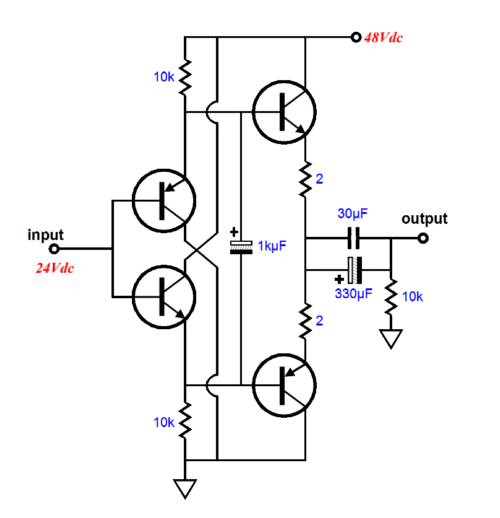
Diamond-Buffer Topology
Adding a capacitor across the output transistor bases helps some, as it allows both input transistors to drive both output transistors over wider voltage swings and further out in frequency.
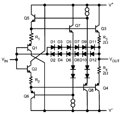
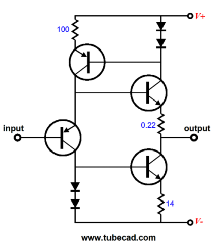
The LMH6321 buffer achieves the same result without a capacitor by using the following topology, wherein the two output transistors have each of their bases driven by a pair of push-pull transistors; the diodes simply allow for the required voltage drops, functioning as coupling capacitors of sorts but with a fixed voltage drop.
In the above topology, resistors R1 and R2 are essential for taking up some voltage slack and they serve to increase the idle current through the output transistors, improving the buffer's distortion figure. There are times when we cannot tolerate a high idle current, say in battery-powered equipment or in high-voltage gear, wherein the large voltages differentials will cause large heat dissipations in the face of high idle current. Using two coupling capacitors and two large-valued emitter resistors is a good workaround in such a situation, as they maintain a fixed bias current and lower the output impedance due to the removal of the output emitter resistors, but at the cost of greater complexity and more expensive parts.
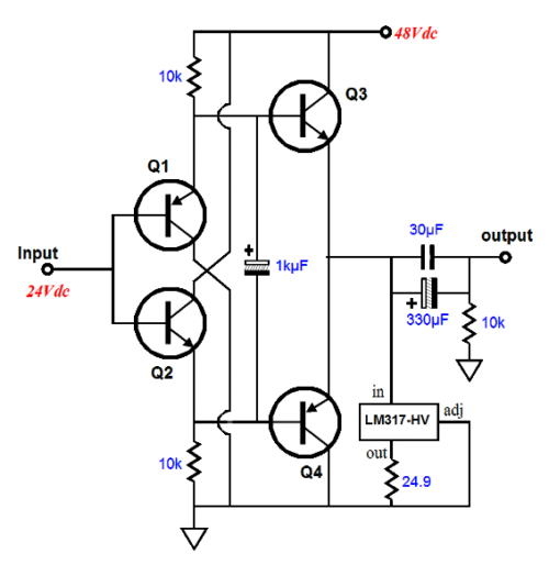
And more help comes from removing the emitter resistors and adding a constant-current source to pull the output stage into an asymmetrical mode, wherein the buffer idles is class-A, single-ended mode, then breaks into class-B with large input signals, signals large enough to provoke transistor Q4 into conduction.
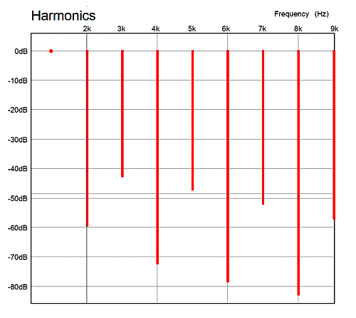
THe LM317-HV is the high-voltage version of the LM317. In the circuit above, the LM317-HV defines a constant-current source, which pulls transistor Q3 into a preset and rich idle current of 50mA, as 1.25V/24.9 (roughly) equals 50mA. Remember, transistor Q4 is shut off at idle. This pull-down technique is effective, in sonic terms, because it breaks the diamond buffers usual pattern of distortion harmonic generations, wherein the even harmonics are suppressed and the odd freely mix with the signal. The ear is not pleased with such an imbalance.
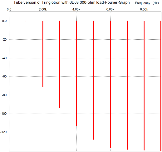
In contrast, single-ended buffers and amplifiers present a more uniform stepping down the harmonics.
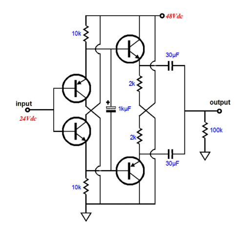
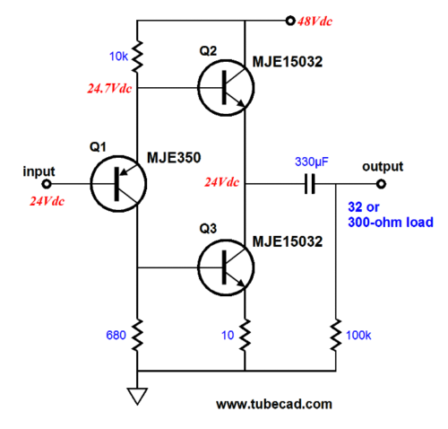
Which leads us to the question: Why bother with a push-pull buffer at all? Why not create a single-ended buffer instead? The following circuit uses two emitter followers and two constant-current sources (CCS) to create a single-ended buffer.
This buffer can be further improved by adding two bypass capacitors, as shown below.
The downside to any single-ended buffer is heat. The idle current must at least equal the maximum expected current demand, for a maximum symmetrical output swing. Because (good) music presents such a wide dynamic range, the high idle current required for peak current swings makes for a lot of wasted heat (but not wasted sonic bliss; I won't tell Al Gore if you don't.) Hence the attractiveness of a dual-mode or asymmetrical output stage operation, as we can enjoy single-ended bliss for 98% of music's duration and still enjoy thunderous crescendos. Replacing the LM317-HV-based constant-current source with a swinging current source helps further the buffer's performance. Transistor Q6 functions not as a CCS, but as a variable current-source. As the output swings positive, it conducts less; as the output swings, negative, it conducts more. This is and example of an asymmetrical output stage and of what Cambridge Audio has trademarked as Class-XD. Nevertheless, the diamond configuration at its core limits the maximum performance. There is only so much performance that can be wrought from cascading emitter followers.
The Triadtron at Last
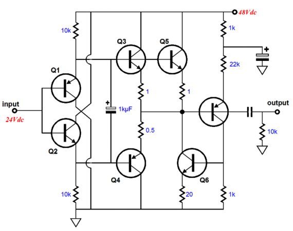
This circuit provided low distortion and an SE-flavored harmonic structure. In SPICE, replacing the the 10k resistor with a CCS made the distortion go up, not down, which inclines me to think that this topology is ironing flat the combined transistors transfer curve by complementary balancing. I like the look of this topology a great deal, but I wanted lower distortion. Further brainstorming resulted in the following topology.
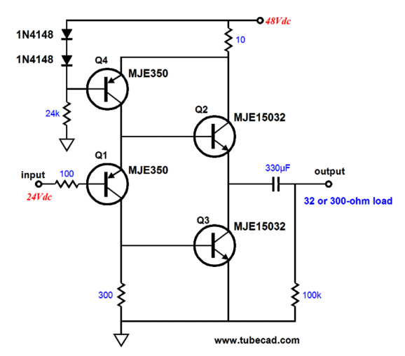
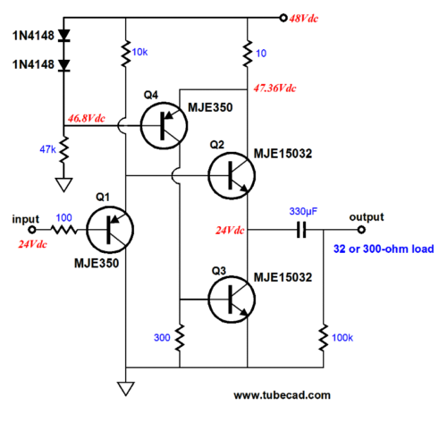
It is a variation on the Taylor amplifier topology, with the bottom MJE15032 transistor (Q3) being indirectly driven by the current flowing through the top MJE15032 (Q2). The topmost MJE350 (Q4) fights to keep the voltage drop across its 10-ohm emitter resistor at a fixed voltage of about 0.7Vdc, which would in turn imply that the top MJE15032 (Q2) also under goes a fixed current draw. In other words, the bottom MJE15032 transistor (Q3) is undergoing all the signal induced current flow variations, while top MJE15032 (Q2) traces the input signal while conducting steadily. And it all works, works quite in fact—until the output voltage swing exceeds the idle current, whereupon the the top output transistor conducts more, while the bottom transistor cuts off. The input transistor, Q1, is not essential, as we could drive transitory Q2's base directly with the signal source; so I still see this topology holding only three key players, making it a trio, not a quartet. In fact, we can separate out Q1 on its own current branch.
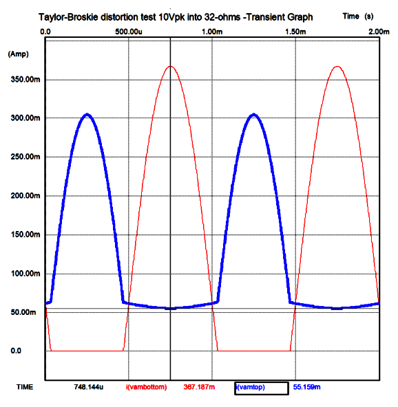
The following SPICE simulation graph shows the current relationships between the two output transistors when delivering 10Vpk swings into a 32-ohm load. Note how the top transistor (blue trace) never cuts off, whereas the bottom transistor does.
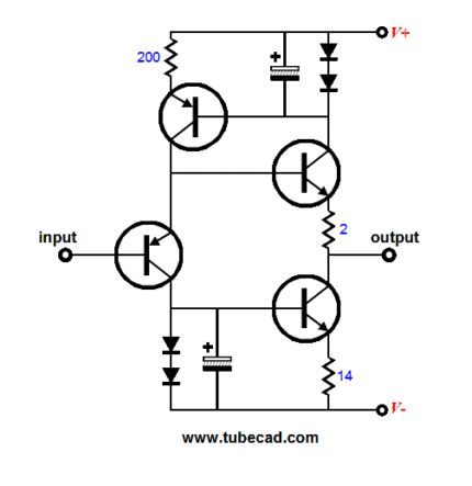
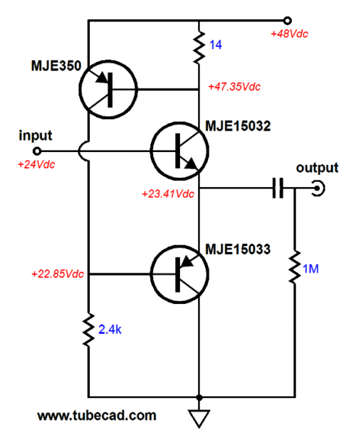
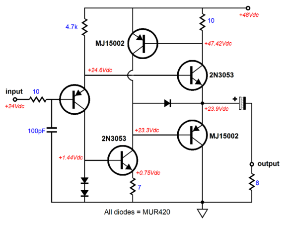
From here, the Triadtron under went several more mutations. Complexity was creeping in and the part count was beginning to swell. I decided to go back to my old notes on buffer circuits. There I found a topology that I falsely remembered being lackluster; it isn't. This topology deserves the "Triadtron" label.
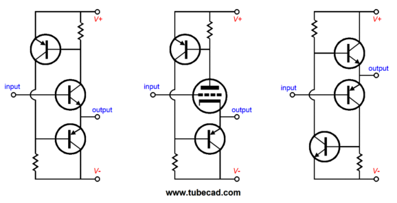
In fact, it's amazing how much performance can be squeezed from just three transistors. Besides from offering low distortion, low output impedance, and good PSRR, this circuit employs a form of auto-bias, as the top MJE350 strives to hold the idle current at 50 mA, which is equal to 0.7V/14ohms; and it works. Like the Taylor variation from the previous example, the top output transistor conducts a steady current up until the demand exceeds the idle current, then the top transistor increases its conduction, while the bottom device turns off. Inside the idle-current envelope, the buffer act very much like a class-A, single-ended buffer, giving rise to a single-ended harmonic structure. Here is the Triadtron in three variations. Yes, the auto-bias feature even works with the hybrid example in the middle. With a few modifications, the Triadtron can be made into a power amplifier.
Next Time
//JRB
|
Kit User Guide PDFs
E-mail from GlassWare customers:
And
High-quality, double-sided, extra thick, 2-oz traces, plated-through holes, dual sets of resistor pads and pads for two coupling capacitors. Stereo and mono, octal and 9-pin printed circuit boards available.  Aikido PCBs for as little as $20.40 http://glass-ware.stores.yahoo.net/ On SALE
Download or CD ROM www.glass-ware.com
|
|||


| www.tubecad.com Copyright © 1999-2010 GlassWare All Rights Reserved |