| John Broskie's Guide to Tube Circuit Analysis & Design |
18 January 2018 Post 409
How to Start a Single-Ended Design
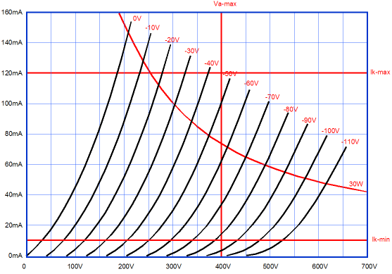
When I was in college, I sought to make The Perfect brownie, which had to exhibit the paradoxical goals of being crunchy on the outside, but moist and chewy inside, with an overpoweringly intense chocolate flavor blended with butter, not too sweet, and certainly not cloying; a dignified, but exuberant brownie. No surprise, my friends were eager to sample my efforts. I replaced coco powder with ground chocolate; vanilla with chocolate extract; oil with fresh butter. I experimented with using just egg whites, then just egg yolks, and finally a ratio of both. Batch after batch of brownies were baked and instantly consumed by my friends. One day, I showed a buddy of mine my notebook, which listed all the recipes I had tried and my evaluation of the results. He was dismayed. When he encountered a note I had written that stated that I must determine the PH of the ground chocolate, he flipped. "What the hell, PH," he grunted. "It stands for potential hydrogen and it is measures of the relative acidity or alkalinity." "I know what PH is. Why are you concerned with it?" "I believe that all my efforts to increase the chocolate flavor has thrown the batter too much towards acid, so I might have to compensate with more baking soda." "No, no, no. You aren't getting it. Why are trying to do science with cooking, which is an art?" That was it. He subscribed to the ever popular notion that art belonged to the subconscious mind, a Freudian sewer whose unseen course denied both reason and categorization. Art stood apart from rationality and forethought. At one end, we find science; at the other end, art; with craft and engineering in the middle. Well, I have known audiophiles who fear attaching an oscilloscope to their tube gear, lest its artistic purity gets soiled by grubby science. I get emails that state, "I own five Audio Diamond Super Elixir resistors. Can I use them in your Aikido design?" That's it, nothing more. Note that no mention of the resistor values was made, nor did he mention which tubes he planned on using or a dozen other useful pieces of information. At the other extreme, I once knew a retired aeronautical engineer. One afternoon, I called him and asked if he wanted to join me in a trip to a faraway electronics store. He did. When I stopped by his house, he showed me his shopping list, which held just three items, yet these three filled an entire carefully written page. I looked over the small, tightly scrawled script and saw that he had made columns with headings, bearing titles such as, Value, Tolerance, Maximum Length, Voltage Limit, Wattage Rating, Expected Price, Possible Substitute… In short, he wanted some 10k and 100-ohm resistors and a pair of 0.33µF coupling capacitors. Still in a stunned state, I asked if he always made shopping lists this detailed. He did, always; didn't everyone? He wasn't an artist. This is all nice, but what does it have to do with single-ended amplifier design? Single-ended designs are different. We must first wear our scientist hat before we can wear our artist's beret. Single-ended amplifier simply require much more care in design than push-pull designs. I have met several musicians who not only fix their tube amplifiers, but modify them, without any deep knowledge of how tube amplifiers works, let alone such concepts as transconductance or perveance. Push-pull amplifiers are far more forgiving. For if nothing else, they can be run in either class-B or class-AB or class-A, whereas a single-ended amplifier must be run in strict class-A. Moreover getting the correct idle current is critical, as either too little or too much will rob the amplifier of potential output power. Where to start is all important. We can either start with the output transformer or the output tube, and each will dictate the other to a large extent. For example, an output transformer with a primary impedance of 20k would be a dreadful match for a 2A3, just a 211 would be a poor match for a 1.6k primary. A good start is to read the data sheet for the output transformer. But at the same time, we must be cautious. Just as 2-by-4 strips of wood are not actually 2 inches by 4 inches, not all transformer specifications are trustworthy. Here is an example that I should never have encountered, yet I have: the output power is specified as 35W, but the transformer holds a primary impedance of 2500 ohms and a maximum idle current of 100mA. What's wrong with this picture? The idle current squared against one half of the primary impedance equals the maximum symmetrical power output, or W = I²R/2. When we do the math, we find 12.5W as the maximum power output, not 35, as 25W would be the accurate, but shameless, specification for peak watts. What went wrong? My guess is that the maker of the output transformer had been making push-pull output transformers and decided to catch the single-ended wave of enthusiasm; they had an easy rule in place for push-pull transformer that dictated so many watts for each pound of weight; the single-ended transformer weighed as much as the 35W push-pull transformer—therefore, it must put out 35W. In fact, we are not likely to realize the full 12.5W, as both the primary and secondary contain DC resistance and the core suffers its own losses, so 10W might be a more realistic expectation. Say we are happy with the 10 watts of output, we still might not get the full amount, even with the 100mA of idle current. Why not? One reason might be insufficient B+ voltage. For example, say the B+ voltage is 250Vdc, a woefully inadequate amount. Why? Once again, we must do the math. The peak symmetrical voltage swing across the primary is equal to the idle current against the primary impedance; thus, with an idle current of 0.1A and a primary impedance of 2500 ohms, the peak voltage swing equals 250V, which would leave zero volts for the output tube. Well, what would be the right B+ voltage? The math states that B+ voltage must at least equal (2Iq × rp) + (Iq × Rprimary) where Iq is the idle current. Assuming an output tube with an rp of 700 ohms and the primary impedance of 2500 ohms and the idle current of 100mA, we would need at least 320Vdc of B+ voltage, which also assumes grid bias, not cathode bias. If cathode bias is used, then the cathode voltage must be added to the total. Moreover, this assumed that the primary presented zero ohms of DCR. It won't in reality. In other words, a bit more B+ voltage should be added. How much more? At least the amount displaced by the output transformer's DCR against the idle current, Iq. Are we done? No, alas. We have been striving to attain the power from the output transformer, but we might have exceeded the output tube's dissipation limit and possibly its plate-voltage limit. Assuming that both these limits have been shown a healthy respect, we can be fairly sure that our single-ended amplifier is functional.
Climbing the Ladder
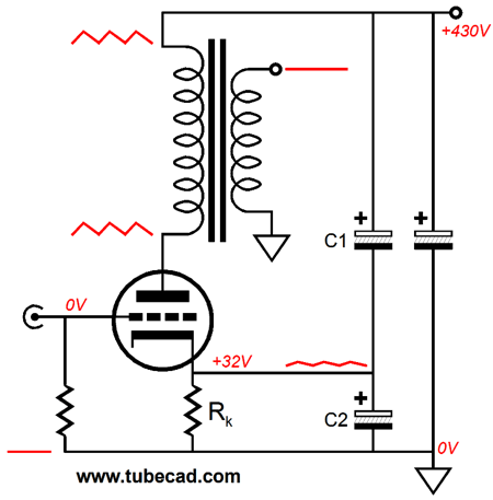
If we are using cathode bias, the best move is to employ some Aikido mojo by adding a capacitor (C1) that bridges the cathode to the B+ voltage. The capacitor prevents the B+ ripple from altering the output triode's current conduction, so the primary becomes immune to the ripple, greatly increasing the PSRR. The capacitor's value must equal the cathode resistor bypass capacitor's value divided by the output triode's amplification factor (mu). For example, if the mu was 10 and the bypass capacitor (C2) was 100µF in value, the added capacitor's value would be 10µF.
I have implemented this Aikido mod for over 20 years now and I am always surprised how much the sound improves. I believe that all increases in PSRR are worthwhile, but this modification seems to go beyond just improved PSRR. Perhaps, some Ultra-Path mojo is obtaining. Moreover, the added capacitor has usually been a high-voltage film capacitor, which in itself can make a big difference. Of course, we should also strive to improve the power supply and not rely on the added capacitor to do all the work. See post 229 for more details.
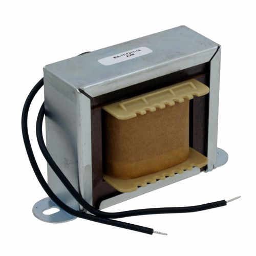
One modification that has always proved worthwhile is to add a choke (or an extra choke) to the power supply. Here is an example: about 12 years ago an audiophile had visited me and asked how he could improve the sound of his tube amplifier. I mentioned several modifications, including adding a choke. As we walked through my garage to his car, I spotted a beefy choke on a shelf. I handed it to him and told him to replace the power supply's 47-ohm RC resistor with it. I also explained that this choke wasn't ideal, as it only offered 100mH of inductance, but until I could dig through my hoard of iron, it would give him an idea of what to expect. A few hours later, he called me and proclaimed that the choke had transformed his amplifier into a true high-fidelity amplifier and that he was thrilled with the results, which proved far more satisfying than the $80 worth of coupling capacitor upgrades he had made the month before. Perhaps a month later, I finally got around to hunting down the choke with a few Henries of inductance. I drove to his place; we first listen to his amplifier with the old choke in place, and then we replaced it with the high-inductance choke. The sound was different, but I was sure that the previous choke actually sounded better. How could this be? More is always more, right? No, not always. Yes, the new choke offered ten times more inductance, but then it also presented ten times more DCR. Had his amplifier been a class-A design, either single-ended or push-pull, then the higher-valued choke might have sounded better; his amplifier was class-AB effort, however, and the choke was shared between two channels. Perhaps the lower DCR choke did a good job of cleaning up rectifier hash, without saturating under heavy demand and without stealing too much potential B+ voltage. We then listened to the amplifier with the choke shorted and the result was definitely worse sound. So, the big choke was better than no choke, but the lower-valued choke proved best.
I have added hash-chokes, which offer tiny amounts of inductance, far lower than 1mH, but are rated for several amperes of current; these, too, have improved the amplifier's sound, when a textbook expectation would be that they could make no meaningful difference, much like 100pF bypass capacitor improving a 4µF coupling capacitor's sound. These additional inductors are not limited to tube-amplifier designs, as solid-state equipment also benefits. I once modified a high-end CD player's I-to-V stage by replacing all the transistors with hand matched ones and replacing all the 1/8th watt metal-film resistors with bulk-foil types. How did it sound? Better, probably about 20%, but not the 200% I had dreamed of attaining. I was quite disheartened by the experience, particularly as I had spent hours of work and hundreds of dollars in fancy resistors. I then spotted the two 100-ohm RC resistors through which the circuit derived its positive and negative power supply voltages. No, I didn't replace them with fancy resistors; instead, I replaced them with hash chokes that consisted of a few turns of magnet wire over a small toroid core. Bingo! I got my 200% improvement—well, at least 100% improvement. The choke's inductance was embarrassingly small, but it did the trick. This was an important lesson for me, and it was quite similar to the one I learned while in college with solid-state power amplifiers, where I discovered—to my astonishment—that bigger-valued power supply capacitors did not necessarily improve the sound, but they could easily burn up rectifiers and melt power switches. (I had gone from two 30kµF/50V capacitors to twenty-four 100kµF/50V capacitors.) About thirty years ago, I encountered in British HiFi magazines the doings of Denis Morecroft and his many radical views on a variety of audio topics, such as thin, solid-core interconnects and speaker cables and small power-supply capacitors being better than large capacitors. At the same time, many of my friends were building capacitor boxes, which held many high-voltage power-supply capacitors and which attached to existing tube power amplifiers through an umbilical cord. In each case, I thought the amplifier sound had moved over towards a solid-state power amplifier sound, which I deemed a wrong direction, even if the bass performance was slightly improved. I argued that what was needed was not more capacitance, but higher-quality capacitance, that they could keep the quantity of microfarads, but use film or oil capacitors instead, which would still require external capacitor box. I then would retell my college experience with the mega capacitance. Actually, I did learn something else from that long ago capacitor experiment: when I unplugged the amplifier laden with mega capacitance from the wall socket, the music played on and it played beautifully. A diminutive high-pitched raspy sonic overlay that I didn't consciously know was there ended and the sound took on a silken texture. I pushed the plug back into the socket and, seemingly even before the prongs made contact, the annoying buzz returned. I pulled the plug out and the tiny, but infuriating, sonic overlay vanished. I will dare to say it: the sound became more tube-like. I was reminded of when someone in your neighborhood has been a running table-saw or a router and you only become aware of its presence when he shuts it off and your shoulders relax and you proclaim, "Thank God." Depending where you live, your wall voltage might rival your sewer connection in terms of contamination. (If I owned a Toyota Prius, believe me, I would take the high-voltage battery out of it and hook it up to tube gear.)
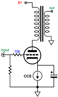
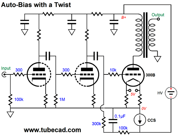
Upside-Down Auto Bias
Another approach would be to place the constant-current source at the plate, not the cathode. Remember that a triode offers three ways to alter its current conduction: a change in grid voltage or cathode voltage or plate voltage. The most efficient control element is the cathode, which is (mu + 1)/mu times more effective than the grid; then the grid is mu times more effective than the plate; or put differently, the plate is 1/mu times as effective as the grid in controlling the triode's current flow. Thus, the constant-current source in series with the plate will also set the desired idle current—and without the need for a shunting bypass capacitor across it. The triode can see either a fixed negative bias voltage or fixed cathode voltage, say by placing a zener or IC voltage reference in series with the cathode and ground.
The supremely great advantage that placing the constant-current source atop the triode, rather than below it, is that all the power-supply noise becomes invisible to the output tube. Effectively the constant-current source acts much like a large-valued inductor would, save for the difference that the constant-current source must displace voltage, whereas an ideal inductor sees no voltage drop. The price we must pay for this supreme benefit is that—because the plate is 1/(mu + 1) times less effective than the triode's cathode—much bigger plate voltage changes will be required than what the same constant-current source would need to make to cathode voltages, were placed in the usual bottom position. If the triode's amplification factor is low, then this would prove less of a problem. Still, we should give the constant-current source a much larger voltage window in which to work. Think of this: say your wall voltage climbs or falls 5%. This would result in the usual B+ voltage of 400V climbing to 420V and falling to 380V. The constant-current source must have a voltage window large enough to absorb these changes in B+ voltage. In addition, it must have enough voltage to adjust a wide variation in output tubes and to work with older, fading tubes or tubes that have grown gassy. With the constant-current source located between ground and the output tube's cathode, the constant-current source must also be able to contend with varying wall voltage and varying output tubes, but it has the advantage of being (mu + 1) times more effective at the cathode than at the plate. In addition, if we use an LM337 configured as a constant-current source, we get the advantage of being able to fix the regulator's tab directly to the chassis. (Thermal grease, but no insulator, would be needed.)
In other words, placing the constant-current source atop the output tube and output transformer will require more thought and planning. Moreover, we must be willing to waste more B+ voltage, which will result in more wasted heat. Nonetheless, the great advantages that accrue from isolating both the output stage and input stage from power-supply noise makes the added effort worth it. In addition, we could use solid-state rectifiers, as this setup would ensure a slow ramp-up of B+ voltage, as the constant-current source will linearly charge up the shunting capacitance across the amplifier. And it would act as a sort of fuse, as it would impose a long-term current limit in the face of a faulty output tube or arcing within the tube. So, what sort of care is required? If we use a zener diode to set a fixed cathode voltage, we should pick a break voltage that will roughly center the constant-current source in its voltage window. For example, say we give the constant-current source 100V within which to operate; we would want the constant-current source to displace 50V. If we use grid-bias instead, we would adjust the grid voltage to center the constant-current source. We must also ensure that the constant-current source can handle the worst-case scenario. For example, with an idle current of 100mA and a constant-current source voltage window of 100V, the device must be able to withstand 10W of constant dissipation. Unlike the constant-current source located at the cathode, this arrangement makes parallel output tubes a tad more difficult, as each output cannot get its own individual constant-current source. This means that matched output tubes would be needed with the single constant-current source This brings up the issue of how to make a high-voltage constant-current source.
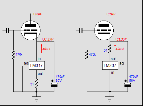
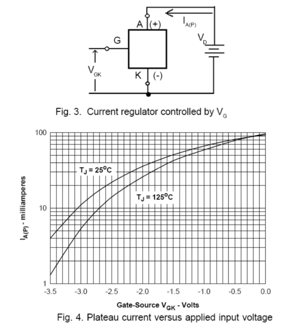
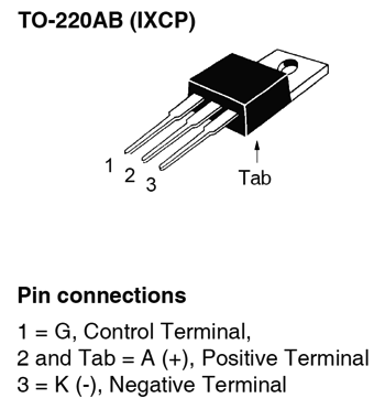
For most audiophiles, the zener diode is the perfect voltage reference. Why? It's not due to it being quiet, as it isn't. It's not due to being accurate, as it isn't. No, what they love about the zener is that it only holds two leads. A closer approximation to a perfect device would hold one lead; no leads, perfection itself. Each added lead or terminal worsens the situation, probably by the square of the leads, so a two-lead device is four times worse than the single-lead device, while a three-lead device is nine times worse. As for fourteen-lead circuits, forget about it; it's not going to happen. Fortunately, IXYS makes two high-voltage constant-current source in a three-lead, TO-220 package: the 10M45S and 10M90S. The first is rated for up to 450V; the second, 900V. Hence, the 45 and 90 in the part names.
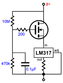
Mounted on a 2.5in tall heatsink, with a thermal resistance of 2.6C/W, even at 10W of dissipation, the heatsink will only rise to 51C, assuming an ambient temperature of 25C. Of course, one constant-current source will be needed per channel. I would use the 10M45S for B+ voltage of up to 400V, say in a 2A3 single-ended amplifier; and the 10M90S with B+ voltage of up to 600V. (I hate going above 600Vdc; it just makes me too nervous.) If a heavy idle current is required, say over 100mA, then we will have to place several in parallel, with each getting its own cathode resistor. If we are willing to get more complex, we could use an LM317 configured as a constant-current source in cascode with a high-voltage power MOSFET.
The high-voltage MOSFET shields the LM317 from the high voltage and dissipates most of the heat. Hell, if we wanted to, we could use a 6AS7 or 6080 in place of the MOSFET.
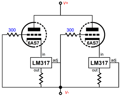
Note how each triode gets its own LM317-HV. By the way, the LM317-HV is the 57V version of the device. The 6AS7 would have to get its own floating heater winding, but the 5Vac winding might be used, if it were rated for more than 3A. (Yes, I know that the tube require 6.3V, but since most old tube power transformers were designed for 115Vac and since most wall outlets here in the USA run over 120Vac, and since the 6AS7's 2.5A heater current draw is less than 3A, the heater is likely to see something closer to 6Vac than 5Vac.) Or, we could simple give the 6AS7 its own dedicated 6.3Vac power transformer.
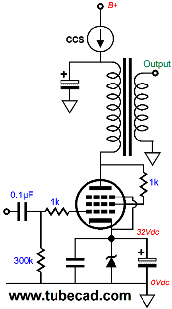
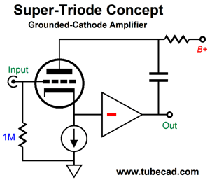
Hybrid Super-Triode Example
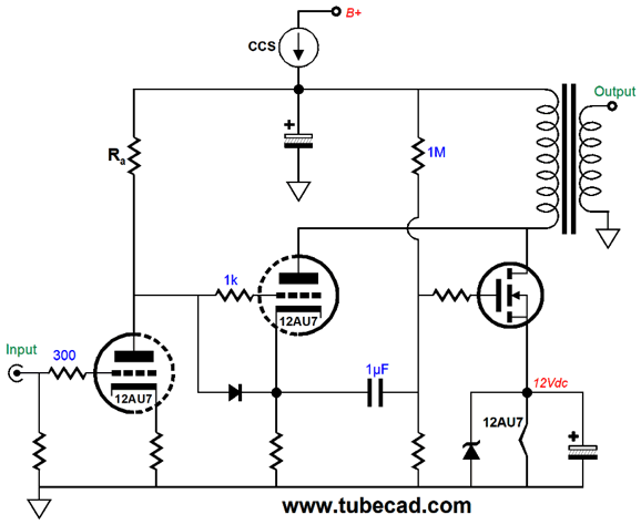
The constant-current source adjusts the B+ voltage to bring the amplifier's entire current conduction up to the constant-current source's preset value. Note the two-resistor voltage divider that gives the MOSFET's gate its sampling of the B+ voltage. If the B+ voltage is too high, the MOSFET will over conduct, causing the constant-current source to low the B+ voltage until the desired current flow is achieved. Note how we get a free 12Vdc heater power supply, as the idle current through the MOSFET is great enough to supply the 12AU7's heater its needed 150mA of current and to make the zener break at 12V. Here is a fleshed out version.
The first and second stages no longer directly couple, as we need all the voltage headroom we can provide the second 12AU7. Of course, this isn't the only possible topology; for example, here is another possibility.
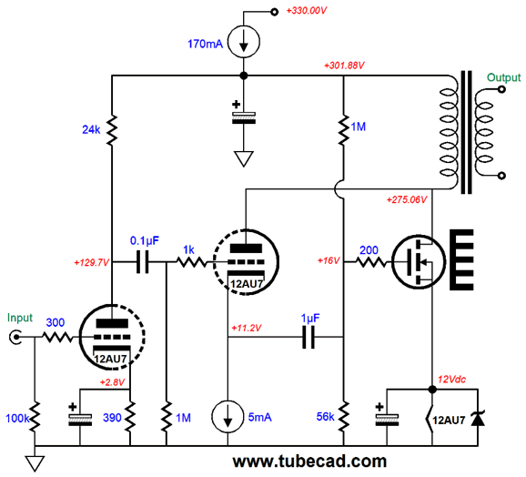
A huge input signal will be needed to drive this amplifier to full output. Nonetheless, tube-based line-stage amplifier can usually swing huge output voltages. The ECC99's heater is not in the MOSFET's source circuit. Why not? IT draws 400mA at 12.6Vdc, which is far too much for any single-ended output transformer I know of; however, if a special, low-winding output transformer were custom made, then we might be able to return the heater to the source.
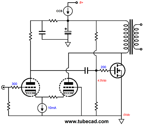
An Down-Upside-Down Variation
Note where ground falls. Note how the 0.1µF shields the 300B grid from ripple, which resides below the constant-current source, not at the B+ voltage. Note that the power supply is floating, i.e. not grounded. Note that each channel would require its own floating power supply. Having said all that, there is still a lot to like here. The power-supply ripple is hidden from the amplifier, both its output stage and its input stages, by the constant-current source. At the same time, the 300B output tube's current is governed by the grid-to-cathode voltage, which makes more efficient use of the constant-current source. The constant-current source can be the same 10M45S or 10M90S devices, or something more complex.
One fantastic advantage to the 10M45S or 10M90S devices is that the TO-220 tab is connected to the anode, so in this, and only this, application, the tab can be connected to the chassis (or at the very least, DC connected to the heatsink, with no insulator).
//JRB
User Guides for GlassWare Software Since I am still getting e-mail asking how to buy these GlassWare software programs:
For those of you who still have old computers running Windows XP (32-bit) or any other Windows 32-bit OS, I have setup the download availability of my old old standards: Tube CAD, SE Amp CAD, and Audio Gadgets. The downloads are at the GlassWare-Yahoo store and the price is only $9.95 for each program. http://glass-ware.stores.yahoo.net/adsoffromgla.html So many have asked that I had to do it. WARNING: THESE THREE PROGRAMS WILL NOT RUN UNDER VISTA 64-Bit or WINDOWS 7 & 8 or any other 64-bit OS. One day, I do plan on remaking all of these programs into 64-bit versions, but it will be a huge ordeal, as programming requires vast chunks of noise-free time, something very rare with children running about. Ideally, I would love to come out with versions that run on iPads and Android-OS tablets.
//JRB |
Special Thanks to the Special 60 (stuck on 60) Only those who have produced a technical white paper or written an article on electronics know just how much time and effort is required to produce one of my posts, as novel circuits must be created, SPICE simulations must be run, schematics must be drawn, and thousands of words must be written.
If you have been reading my posts, you know that my lifetime goal is reaching post number one thousand. I have 592 more to go. My second goal is to gather 1,000 patrons. I have 940 patrons to go.
And
High-quality, double-sided, extra thick, 2-oz traces, plated-through holes, dual sets of resistor pads and pads for two coupling capacitors. Stereo and mono, octal and 9-pin printed circuit boards available.
Designed by John Broskie & Made in USA Aikido PCBs for as little as $24 http://glass-ware.stores.yahoo.net/
The Tube CAD Journal's first companion program, TCJ Filter Design lets you design a filter or crossover (passive, OpAmp or tube) without having to check out thick textbooks from the library and without having to breakout the scientific calculator. This program's goal is to provide a quick and easy display not only of the frequency response, but also of the resistor and capacitor values for a passive and active filters and crossovers. TCJ Filter Design is easy to use, but not lightweight, holding over 60 different filter topologies and up to four filter alignments: While the program's main concern is active filters, solid-state and tube, it also does passive filters. In fact, it can be used to calculate passive crossovers for use with speakers by entering 8 ohms as the terminating resistance. Click on the image below to see the full screen capture.
Tube crossovers are a major part of this program; both buffered and un-buffered tube based filters along with mono-polar and bipolar power supply topologies are covered. Available on a CD-ROM and a downloadable version (4 Megabytes). |
||


| www.tubecad.com Copyright © 1999-2018 GlassWare All Rights Reserved |