| John Broskie's Guide to Tube Circuit Analysis & Design |
19 November 2008
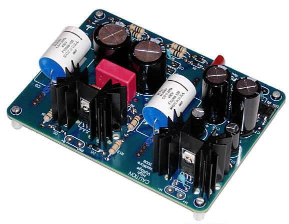
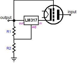
PS-1 Solid-State Regulator Kit A bit of history: I designed this high-voltage regulator several years ago and I laid out a PCB for it in 2007, which actually had a production run. Unfortunately, I had screwed up the pin out of one of the high-voltage devices, so I scrapped it. Although the workaround was simple and easy, I feared that some future owner of the PCB, not knowing of the workaround, might try setting the board "straight." Thus, I decided to play it safe and redo the PCB layout. (I once fixed a friend's Dynaco ST-70, which was the cleanest ST-70 that I had ever seen, as it had sat in the original box the kit came in. It had been assembled, but it never worked, so back into the box it went, waiting for me to show up 40 years later. The power transformer held mismarked secondary leads, as the center-tap lead was marked as one of the outside leads and one outside lead was marked as the center-tap. I went against the markings and wired the transformer up correctly. The then ST-70 worked perfectly. Still, I am uncomfortable with the thought that at some future date, the amplifier will fail and the fellow who fixes it will probably undo my fix in the process.) The inspiration for the PS-1 regulator came from my reading the data sheet for the LM317—not the current PDF from National Semi, but the old book-bound data sheet from the late 1970s, which showed the following high-voltage-regulator topology.
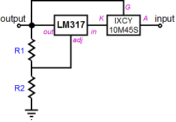
The triode protects the low-voltage LM317 from silicon-melting high voltages; the LM317 establishes the fixed output voltage. Because the LM317 is comfortably nested in the voltage differential that develops between the triode’s cathode and grid (as long as the differential does not exceed 37V) the LM317 is safe, no matter how high the plate voltage. In fact, I believe that the original data-sheet schematic showed a 2,500-volt power supply attaching to the triode’s plate. Making the translation to an all-solid-state design requires finding a solid-state pass device that exhibits a depletion-mode conduction of current. In other words, we need to find a device that can be biased by a resistor at the emitter or source or cathode of the device, much as a vacuum tube can. Thus, an NPN transistor or an enhancement-mode N-channel MOSFET could never work in this topology. One possibility is the Infineon BSP135, a 600V depletion-mode MOSFET; unfortunately it is a surface-mount device, which is not suitable for a kit. Another canidate is the DN2540N5, which is a 400V, 15W device, which is a tad wimpy. The pass device I settled on was the IXCY 10M45S, which is a 450-volt, 300mA, 40W device and is readily available. (The IXCP10M90S and the IXCY10M90S are 900V devices, which would definitely prove useful in higher-voltage applications, but as the intended target range of output voltage for the PS-1 was between 200V to 300V, the 10M45S should prove adequate.)
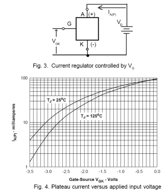
Now the interesting question is, Within how much differential voltage will the LM317 have to work? The answer is, Not much. Below is the graph of the cathode-to-gate voltage versus anode current for the 10M45S.
First, note the negative temperature coefficient, which means that the idle current drops with increased temperature—a wonderful attribute. Like a nuclear reactor with a negative temperature coefficient of reactivity, a pass device with a negative temperature coefficient of conductivity is inherently self-controlling and, thus, much safer. Second, note that 10Ma of current flow requires a 3V voltage differential; 50mA, about 1.5V. While 3V is enough to run an LM317 successfully, 1.5v is a bit too close to its minimum voltage differential. So a low-dropout-voltage regulator is needed, such as the LT1085 or LD1085.
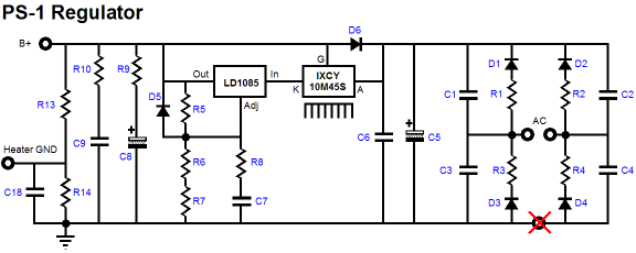
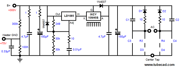
Above is the full schematic for the PS-1 regulator. The 10M45S receives the heatsink, not the LD1085, as the 10M45S will dissipate much more heat than the three-pin regulator. The red X through the bottommost eyelet marks the use of a non-center-tapped primary on the power transformer. On the other hand, if a full-wave, center-tap rectifier configuration is desired, then the following arrangement can be used.
Note all the extra resistors, such as R1 to R4 and R7 to R10. Each rectifier gets its own series resistor, which will help the solid-state rectifier better mimic a tube rectifier. Capacitors, C7, C8, and C9 find a series resistor that serves to protect the solid-state regulator from the capacitor’s high voltage and inherent series inductance. Two resistors, R6 and R7, are used to set the output voltage, rather than one resistor, as these resistors must dissipate a good amount of heat. The total wattage dissipated equals 5mA against the output voltage. So, for example, a 300V regulator output voltage against 5mA develops 1.5 watts of heat. Using two resistors splits this dissipation, which allows greater freedom in resistor choice. The PS-1 regulator PCB, like the Janus PCB, also holds a low-voltage regulator for heating the heaters. The schematic for this regulator can be found in the description of the Janus regulator in blog 149, as they are identical. The PS-1 kits are now available at the GlassWare Yahoo store and, until the next production run is complete, only ten kits are obtainable.
Janus Regulator User Guide
Although I quickly sold out of the Janus regulator kits, I have more boards on order and I have completed its user guide. This fat beast is 24 pages long and covers much more than just the Janus regulator. In other words, I recommend that everyone interested in high voltage power supply design to download the PDF version of the user guide.
//JRB
|
Kit User Guide PDFs
E-mail from GlassWare Customers
High-quality, double-sided, extra thick, 2-oz traces, plated-through holes, dual sets of resistor pads and pads for two coupling capacitors. Stereo and mono, octal and 9-pin printed circuit boards available.  Aikido PCBs for as little as $24 http://glass-ware.stores.yahoo.net/
Support the Tube CAD Journal & get an extremely powerful push-pull tube-amplifier simulator for TCJ Push-Pull Calculator
TCJ PPC Version 2 Improvements Rebuilt simulation engine *User definable
Download or CD ROM For more information, please visit our Web site : To purchase, please visit our Yahoo Store:
|
|||


| www.tubecad.com Copyright © 1999-2008 GlassWare All Rights Reserved |