| John Broskie's Guide to Tube Circuit Analysis & Design |
22 August 2021 Post Number 543
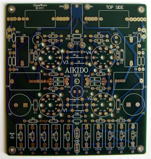
Aikido MFB Filter PCB
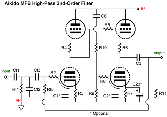
Of course, the list of frequencies is not exhaustive. But this should not prove all that big a problem, if you are sneaky. For example, say you wish to crossover at 430Hz, but the table only lists 400Hz and 500Hz. The workaround is to see if it lists 4300Hz. Indeed, it does. If we keep the resistor values and increase the capacitor values by tenfold we get the values for 430Hz. What if we wanted 215Hz instead? We would keep the resistor values for 4300Hz and multiply the capacitor values by 20. Here is another possibility: you cannot source the required 1% 10nF capacitors, but you can buy 1% 1nF capacitors. In this case we use the 1nF capacitors but increase the resistor values by tenfold. The PCB holds two MFB filters based on the Aikido gain stage. If a two-way active crossover is needed, then two PCBs must be used. Here is a 2nd-order, high-pass filter configuration.
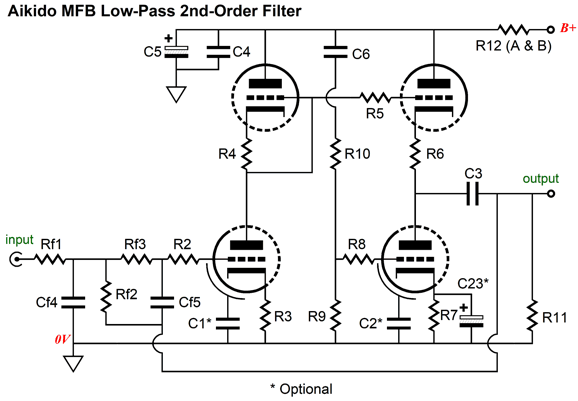
And a 2nd-order, low-pass filter configuration.
Note how the Rf and the Cf resistors and capacitors just swap positions. The MFB filter PCBs and part kits are available now at the GlassWare/Yahoo store until they run out. The required filter resistors and capacitors are not included, as I could never stock that many differing values.
Solid-state Power Buffer
He was probably right, but my design required eight pins. Well, our back and forth strayed off onto other audio topics, such as his workplace keeping the few analog EEs employed separate from the digital EEs, as they feared analog madness contaminating the sober digital workforce and the stodgy digital crowd depressing the analog creativity.
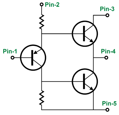
At the top of my wish-list for new solid-state devices was a 5-pin adjustable regulator that would allow using a discrete voltage reference and a separate pin for the pass-device's collector.
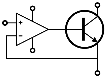
By placing the needed voltage reference outside the IC package, we could use an external high-quality voltage reference and bypass it with a large-valued capacitor, which would lower the regulator noise and allow for a slower ramp up to full output voltage. The separate pin for the pass-devices collector would allow the inclusion of a high-voltage internal pass transistor and the possibility of using a separate floating power supply for the internal OpAmp. Well, another missing solid-state device in the 5-pin TO-220 package was a simple class-A, push-pull power buffer.
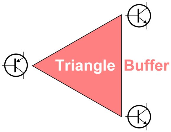
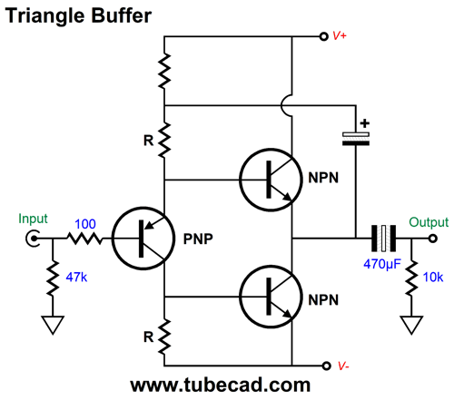
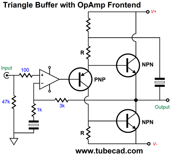
In post 232, I labeled this design the "triangle buffer," offering it as an alternative to the famous diamond topology. Unlike the diamond, the triangle buffer uses the same polarity output devices, either two NPN transistors or two PNP transistors or two N-MOSFETs or two P-MOSFETs or two triodes or two pentodes. This is a huge feature as true matching is possible, as the exact same output device is used top and bottom. When we compare the triangle buffer to a comparable diamond buffer, we find that the triangle produces more 2nd harmonic distortion, but less high harmonic distortion. (See the graphs in post 232). This is a feature. What is not a feature is that the triangle buffer requires a large-valued bootstrap capacitor, which precludes encapsulating the entire circuit in an IC package. On the other hand, with a 5-pin TO-220 package, we can add the needed capacitor externally.
Here is the circuit with the 5-pin package.
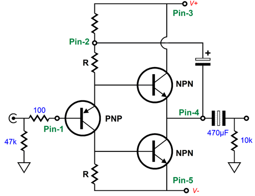
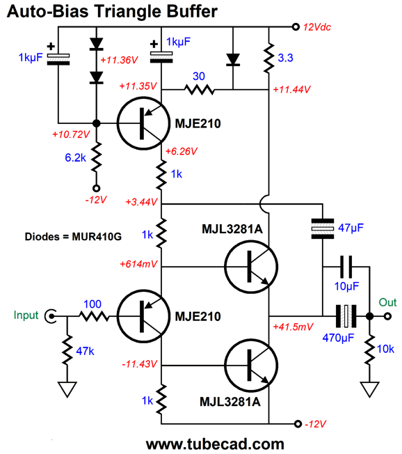
I went searching my hard-drive for SPICE circuits of the triangle buffer, and I found the following circuit that I had forgotten that I had created.
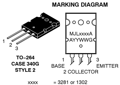
Two features stand out: auto-bias of the output stage idle current and no emitter resistors. I remember Richard Vandersteen telling me that he hated emitter resistors in output stages as they just got it the way. Well, due to the auto-bias circuitry, no emitter resistors are needed. (No output-protection circuitry is included, as the output coupling capacitor pretty much protects the top output transistor from burning up due to a shorted output, which is a huge problem with headphones.) The two MJL3281A output transistors are beefy TO-264, 15A, 200W devices used in high-power amplifiers.
The way the auto-bias circuitry works is that the current flowing through the 3.3-ohm collector resistor is monitored by the topmost PNP transistor through the 30-ohm emitter resistor. If the voltage drop across the 3.3-ohm resistor grows too high, the top PNP transistor ceases to conduct, which will shut down the output stage. If the voltage drop is too little, the top PNP transistor will increase its current conduction to make up for the missing output stage current flow, causing the output stage idle current to rise. The shunting rectifier clips the maximum voltage drop across the 3.3-ohm resistor to about 0.6V. The two rectifiers in series define a simple voltage reference for the top PNP transistor's base. The 6.2k resistor terminates into the negative power-supply rail for safety reasons. If both power-supply rails get their own fuse, the bottom fuse opening will collapse the reference voltage for the top PNP transistor. How well does this circuit perform in SPICE simulations? Not bad at all.
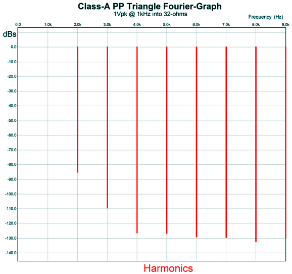
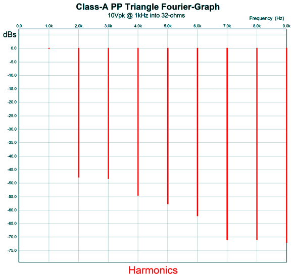
A lovely single-ended cascade of harmonics and the THD was below 0.01%. The load was 32-ohms and the idle current was 170mA. Each NPN transistor dissipates about 2W at idle. The peak class-A output current swing should be 340mA, which implies a 10.9Vpk output voltage swing. Except—the bipolar power supply rail voltages are not high enough to allow such big swings. In SPICE simulations, the actual limit was about 10Vpk. Here is the Fourier graph with 10Vpk of output at 1kHz into 32 ohms.
The THD comes in at 0.64%. When we examine the current flows, however, we see that we have left class-A operation.
In the SPICE simulations, the maximum voltage swing within the confines of class-A was 9Vpk, which is huge for a headphone amplifier, as it results in 1.26W or, as other put it, 1260mW. With 9Vpk of voltage swing, the THD fell to 0.2%.
Mind you, 9Vpk is crazy high output for all but the most inefficient headphones, i.e. some of the planar types. Here is the transient graph for 9Vpk of output.
It's hard to see, but the output transistors never fall below 6mA of current conduction, which meets the first requirement for class-A operation. If we are willing to live dangerously, we can DC couple the output.
The OpAmps works to eliminate a DC offset at the output (assuming no DC offset voltage from the signal source) and provides a gain of 1:4 or 12dB, which should prove enough for headphone listening. The danger enters the picture due to no output-transistor-protection circuitry.
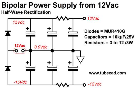
Bipolar Power Supply from 12Vac
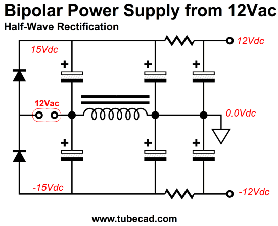
Only two rectifiers are needed. The AC voltage alternately charges the positive-rail capacitor and then the negative-rail capacitor. The ripple frequency is the same as the wall voltage frequency; and the ripple on both rails are not symmetrical, which make Aikido mojo power-supply noise techniques impossible. Nonetheless, the two RC filters do a fair job at scrubbing away the ripple. We can also resort to brute force by replacing the two RC-filter resistors with inductors or with a single common-mode inductor. One trick that I have used with good results is to use one choke.
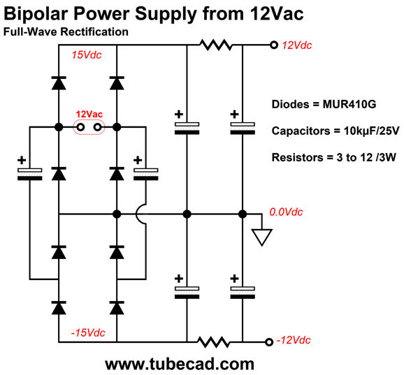
The choke somewhat smoothes away the harsh ripple artifacts, but mostly equalizes the ripple between rails. Just about any amount of inductance helps, say from 100mH to 1H. The better arrangement is the full-wave rectifier setup, but it requires many more parts. In addition, few know that it exists.
Lots of capacitors and rectifiers, true enough, but the results are far better. The capacitors might seem to be voltage overrated, but I would stick to the 25V rating, as wallwart transformers offer extremely poor regulation. Transformer regulation refers to the difference between unload and loaded secondary voltages. A massive 1kVA 12Vac toroid might exhibit half a volt difference between the two loads. In contrast, a 12Vac wallart might deliver 19Vac unloaded. (19Vac peaks at 26.9V.) The 25V voltage rating buys us some latitude in transformer choice.
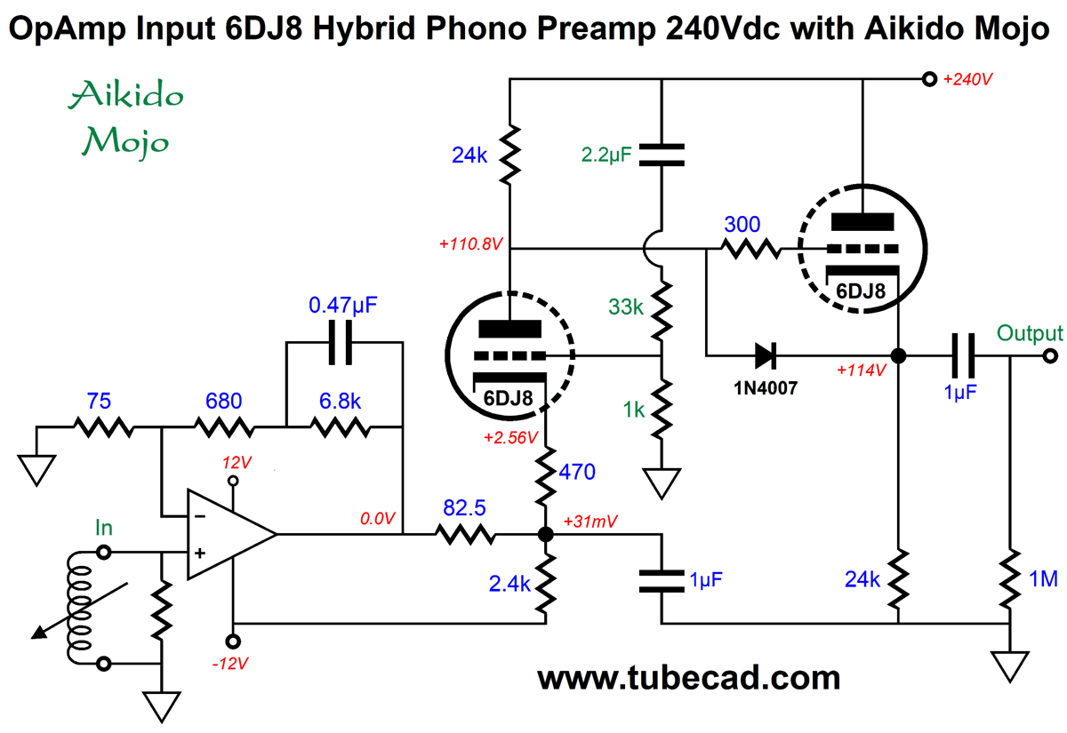
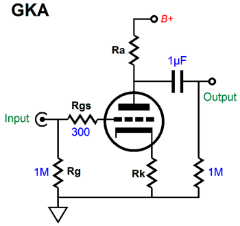
Hybrid Phono Preamps
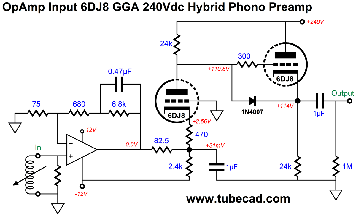
The OpAmp delivers a gain of 20dB at 1kHz and 40dB at 10Hz. In other words, the OpAmp covers the first two time constants of the RIAA equalization curve, 3180µs and 318µs. The 82.5-ohm resistor and 1µF capacitor define a passive low-pass filter at 2122Hz, which completes the 75µs time constant of the RIAA equalization. This might not seem to make sense, as a 75-ohm resistor is needed to create a 75µs time constant. The solution is found in realizing that the 2.4k and 470 ohm resistors are effectively in parallel with the 82.5 ohm resistor. Indeed, the 470-ohm cathode resistor is also in series with the cathode impedance. Here is the math: the cathode output impedance is equal to the sum of the plate-load resistor added to the triode's plate resistance (rp) divided by the triode amplification factor plus one, Zout = (Ra + rp)/(mu +1) or, in this example, 794 = (24k + 3k)/(33 +1). Placing 82.5 and 2.4k and 794 all in parallel gives us 75 ohms.
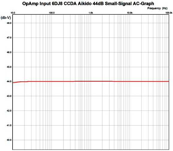
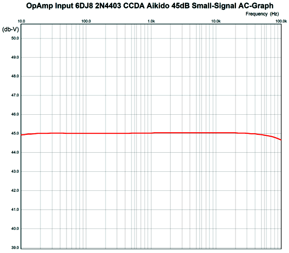
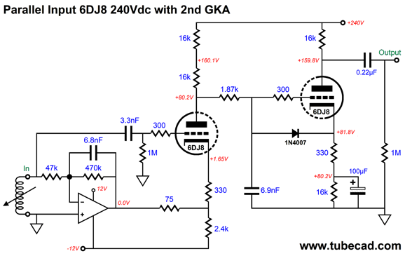
(Note the 1dB divisions, not the usual 10dB. The frequency plot is flat to within 0.3dB from 20Hz to 20kHz.) In other words, the tube-based circuit sees a flat signal at its cathode, as all the needed equalization has been completed. The only task remaining for the tube-based circuit is further amplification. The 6DJ8-based grounded-cathode amplifier cascading into the cathode follower output stage delivers a final gain of 24dB, making for a total of 44dB. If we desire less gain, we could use a 6SN7 or 12AU7; if we desire more gain, a 6AQ8, 6N1P, 12AY7, 12AT7, 6SL7, 5751, or 12AX7 (12DW7). The 6DJ8 wins in low-noise competition. Speaking of low noise, we can greatly improve upon the grounded-grid amplifier's PSRR by injecting some Aikido mojo.
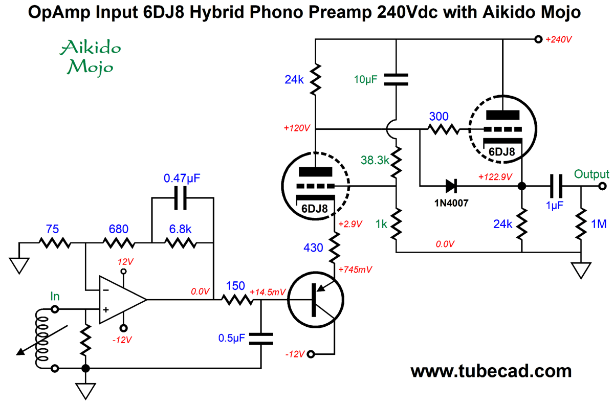
The two-resistor voltage divider defined by the 33k and 1k resistors in series leak 1/34th of the power-supply noise to the grid, which the 6DJ8 triode then amplifies and inverts at its plate, creating a power-supply-noise null at the plate. Unfortunately, the 82.5-ohm resistor and 1µF capacitor introduce some phase shift, so the null is not as deep as it could be. Here is the workaround.
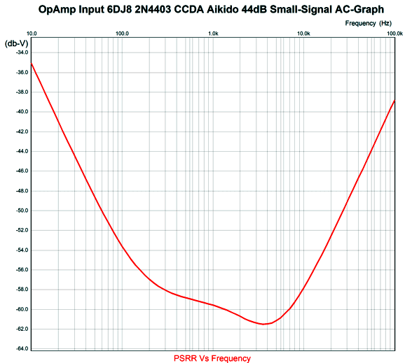
The 2N4403 PNP transistor isolates the cathode resistor from the 212Hz low-pass RC filter. The old 75µs low-pass filter has been replaced by 550 ohms and 0.5µF (we could also use 750 ohms and 0.1µF instead, as both combination yield the same time constant of 75µs). The cathode resistor has been reduced to 430 ohms to compensate for the base-to-emitter voltage drop of about 0.7V, which forced a recalculation of the Aikido-mojo voltage-divider ratio. In addition, I replaced the 2,2µF mojo capacitor with a 10µF capacitor. The result is a PSRR of about 54dB at 100hz.
The hybrid phono preamp's frequency response remains unaltered and quite flat.
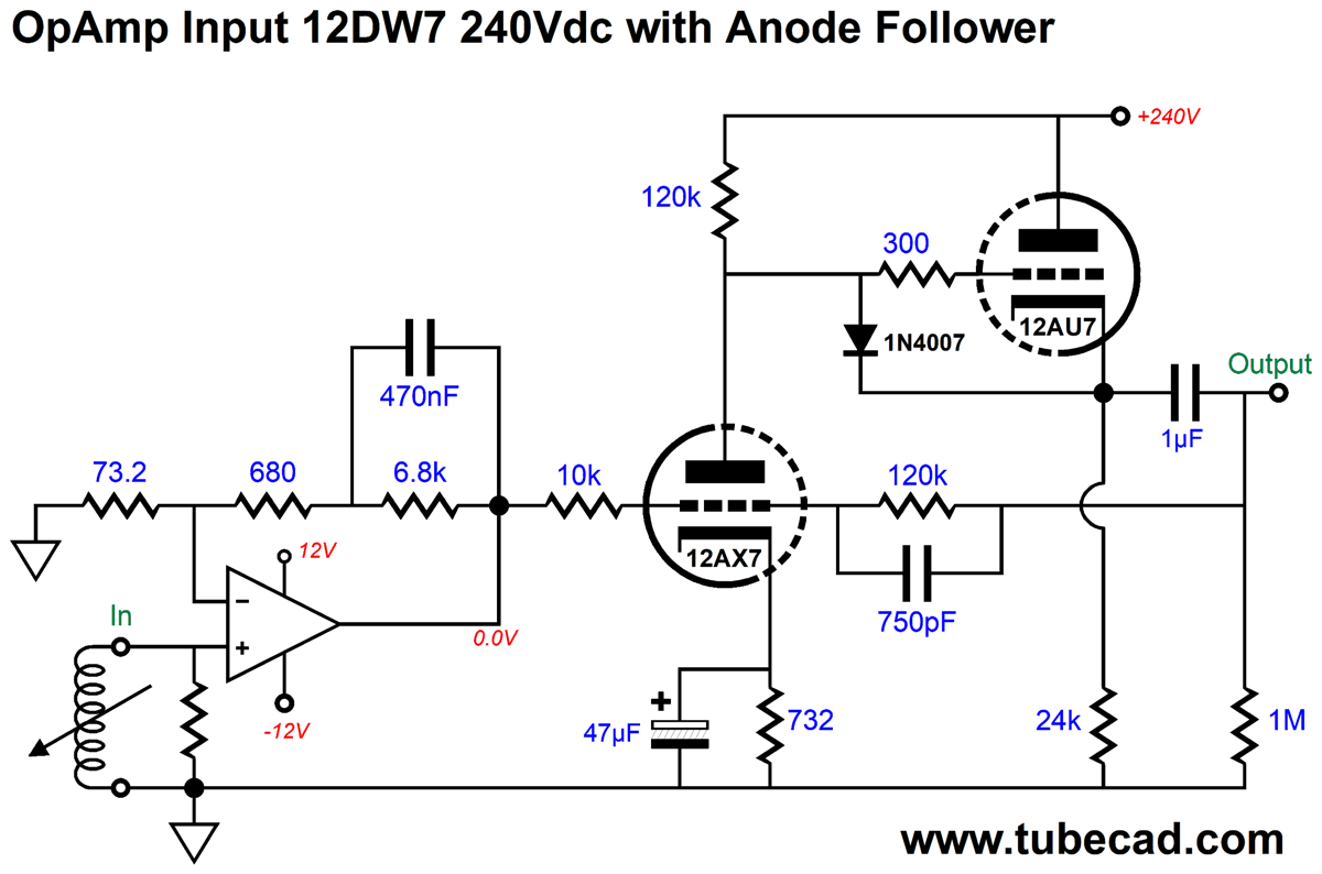
The Y-axis divisions are in 1dB, not the usual 10dB we see in ads or product brochures. I love the frugality of this design, as one tube per channel is sweet. In addition, tube aging will not alter the RIAA equalization. We can get away with an unregulated power supply, as two cascading RC filters should prove sufficient. (I would certainly use, however, a regulated bipolar power supply, such as my PS-22 or Dual/Bipolar LV-Reg, for the OpAmps.) In fact, I would give the 6DJ8 heater elements their own floating regulated power supply referenced to +60Vdc. Another possible topology is to use an anode-follower with active completion of the RIAA equalization. Once again, an OpAmp develops a gain of 20dB at 1kHz and 40dB at 10Hz, as the OpAmp covers the first two time constants of the RIAA equalization curve, 3180µs and 318µs. The tube-based anode follower delivers a closed-loop gain of 20dB, bringing the total to 40dB.
The this anode-follower consists of a grounded-cathode amplifier cascading into a cathode follower. It doesn't qualify as a constant-current-draw amplifier, since the current draw is not constant. A 12DW7/7047/ECC832 dissimilar-triode tube is used, with the 12AX7 triode in the grounded-cathode amplifier and the 12AU7 triode in the cathode follower. The anode-follower's open-loop gain is 53 (about 34dB); its closed-loop gain, 20dB. Thus, the amount of negative feedback is 14dB. With the 750pF capacitor shunting the 120k negative feedback resistor, the 75µs (2122 Hz) portion of the RIAA equalization is accomplished. In other words, the amount of negative feedback increases beyond 2122Hz, rising to 34dB at 20kHz. (The recorded frequencies above 2122 Hz on an LP also rise at 6dB per octave or 20dB per decade, so the result is a flat playback.) When dealing with negative feedback in an amplifier, the internal coupling capacitors and cathode bypass capacitors become an important issue. For example, the 47µF cathode bypass capacitor value may seem arbitrary, but it isn't. Too large a value can cause peaking in the low frequencies; too low a value, a dip in low-frequency output. Ideally, we do not want to terminate the negative feedback 120k resistor and its shunting capacitor into the other side of the output coupling capacitor, as that would place this coupling capacitor inside the negative feedback loop. The workaround is to DC terminate the two into the cathode follower's cathode.
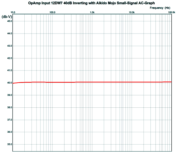
Note that the grounded-cathode amplifier's cathode resistor value has been increased from 732-ohms to 10.2k. DC current flows through the 120k and 10k resistors, which the OpAmp must sink. Is this a problem? No, as 123.4Vdc/(120k + 10k) = 0.95mA of current flow, which all OpAmps can handle. In addition, this current flow helps force a larger class-A range of operation from the OpAmp, as the current forces a crossover displacement. This is a decades-old trick to improve the sound of OpAmps, which usually use a resistor that bridges the OpAmp output to the either the positive or negative power-supply rail. The only real difference, other than the larger cathode resistor value, is that the 47µF capacitor must be rated for 16V rather than 6.3V. Note that the anode follower inverts the signal phase at its output. Is this a big deal? No. In fact, I deem it an advantage, as it lessens the chance that the output will cause problems by coupling to the input due to stray capacitances. If you deem it a problem, then you simply need to reverse the leads on the phono cartridge, so the blue wire goes to the left hot and the white wire goes to the left negative; the green to right hot; and the red to right negative. How flat is the RIAA equalization? Very flat, as in +/-0.01dB from 20Hz to 20kHz.
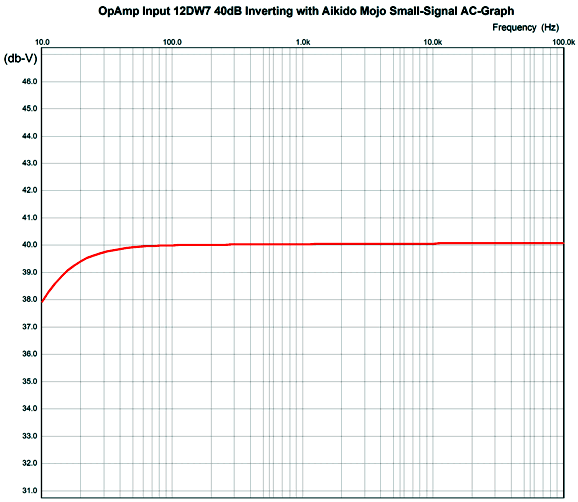
Actually, this is the frequency response at the cathode follower's cathode. With a 1µF output coupling capacitor and 20k volume potentiometer, the frequency plotline looks like this.
As you can see, the low-frequency -3dB cutoff frequency is below 10Hz. Although both these phono preamp design are perfectly fine and quite useable, they have also been a mental warm-up for what will follow.
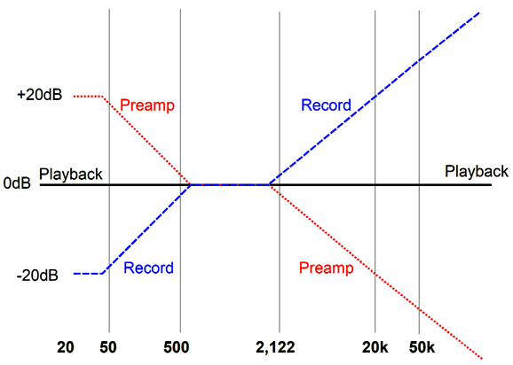
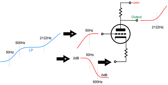
Bi-Amped Phono Preamps The LP's recorded sound is not flat, but equalized to extend playing time and reduce noise. Low-frequencies are reduced and highs are boosted. The phono preamp's job is to both provide gain and inverse equalization to produce a frequency-flat output signal.
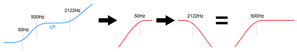
In the graph above, we see three transition frequencies: 50Hz, 500Hz, and 2122Hz. If we apply a 1st-order 50Hz high-pass filter to the LP's output signal, only two transition frequencies remain: 500Hz and 2122Hz. If now apply a 1st-order 2122Hz low-pass filter to this signal, we get one transition frequency: 500Hz. In fact, it looks like the application of a simple 1st-order 500Hz high-pass filter to a full-bandwidth signal.
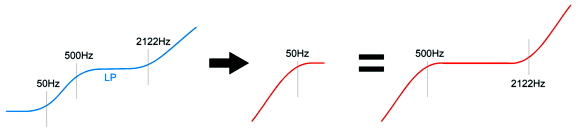
Amazingly enough, if we apply a 1st-order 50Hz LOW-pass filter to the LP's output signal, once again only two transition frequencies remain: 500Hz and 2122Hz. This time, however, a shelving response occurs, starting at 500Hz and ending at 2122Hz.
If now apply a 1st-order 2122Hz HIGH-pass filter to this signal, we get one transition frequency: 500Hz. It looks like the application of a simple 1st-order 500Hz LOW-pass filter to a full-bandwidth signal. Combine these two signals together and we arrive at a flat frequency response. Okay, how do we combine the two signals?
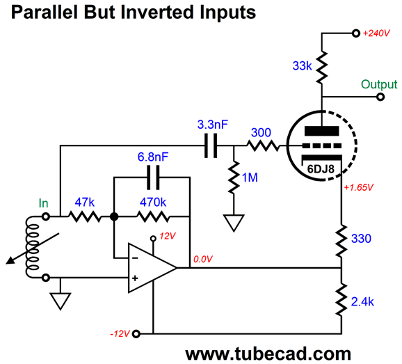
A grounded-cathode amplifier actually has two inputs: the grid and the cathode, with the cathode offering a mu of (mu + 1). In other words, the cathode is (mu + 1)/mu times more effective than the grid in controlling the flow of current through the triode. With a 12AX7 this makes little difference, as its mu is 100; but with a 6AS7, the difference is substantial, as its mu is only 2, so its cathode is (2 + 1)/2 or 1.5 times more effective than its grid. Unfortunately, we cannot hope to mix the signals without some more work, as the cathode does not invert the signal phase as the grid does. The workaround is to pre-invert the signal before passing it along to the cathode. Actually, this not the liability that it may seem, as we need to amplify the signal's low frequencies before injecting it into the cathode, as we need to perform the 50Hz to 500Hz shelving first. We must also devise a means for introducing the 50Hz high-pass filter on the grid's signal. Here is how we do both:
That's the overview. Here is the implementation.
The 3.3nF input coupling capacitor and the 1M grid resistor impose the 50Hz high-pass filter, while the OpAmp's negative feedback loop imposes the 50Hz to 500Hz shelving. At the triode's plate, the output signal is still not flat, as we still have the rising slope above 2122Hz. We must follow with a 2122Hz low-pass filter, R and C.
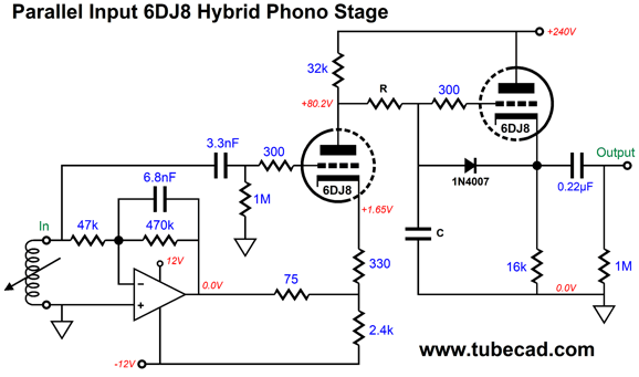
The 75-ohm resistor in series with the OpAmp output allows us to trim the bass gain. The 75-ohm and 2.4k define a two-resistor voltage divider, which in this case reduces the OpAmp's output by 1/33th. In other words, we have brought the cathode's gain down to the grid's gain. In addition, the 2.4k R resistor provides a current path to the -12V power-supply rail for the triode. The 1.87k resistor is in series with the triode's output impedance, so the two resistances combine and work with the 5.9nF capacitor to impose the 75µs time constant, completing the inverse RIAA (IEC) equalization. The cathode follower simply buffers the output. As the circuit stands, the final gain is 26dB, 14dB short of 40dB. This amount of gain might prove sufficient for those who want to "rip" their LP collection to their hard drive. To bring the gain up requires an extra gain stage.
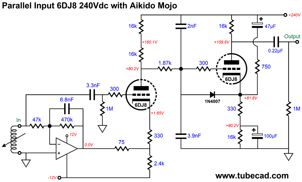
The cathode follower has been replaced by a grounded-cathode amplifier that is DC coupled to the low-pass filter. The resulting gain comes in at a tad over 50dB. Now we get sneaky. We must to do so, as the circuit's PSRR is positive (+13.4dB), not negative; in other words, whatever power-supply noise resides on the B+ voltage will be amplified by the two grounded-cathode amplifiers at the output. The workaround is to inject some Aikido mojo in the form of my Cynosure resistor and by using two capacitors in place of the single 5.9nF capacitor.
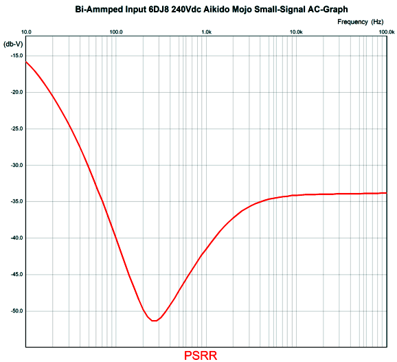
The PSRR now falls to -43dB at 120HZ and -51dB at 270Hz.
The 47µF, 100µF, 2nF, and 3.9nF capacitor values are not arbitrary, nor are the 750-ohm and 330-ohm resistor values. The output coupling capacitor value depends on the line-stage amplifier's volume control resistance. With a 20k potentiometer, 1µF works well; with 100k, 0.22µF.
Music Recommendation: Familiar Female Singers I was disappointed to see that Amazon Music didn't offer a single high-res album of 10,000 Maniacs. Undaunted, I played the first album I had never heard of before, MTV Unplugged. Dang. It sounds good. Recorded live back in 1993, the sound is excellent. Natalie can sing! And singing live before a large audience requires much more from a singer than singing in a recording studio, where do-overs and help from the recording engineer are possible. (The other three albums are available in high-res formats at Amazon Music.)
Aimee Mann is one of those singers that I often forget how well she can sing. Mental Illness is a concept album that shatters her reputation as a singer of pop love songs. (Still, Bachelor No. 2 or, the Last Remains of the Dodo is a better album.) I had forgotten that Edie Brickell was born and raised in Texas, but hearing her deliver believable country music on a single with Willie Nelson quickly restored that old memory. (One memory I never had was that she is married to Paul Simon. Really? Isn't she really tall? Isn't Paul Simon really...) Suzanne Vega no longer sounds young, but her voice retains her signature sound and phrasing. For system showing off, try her 1992 album, 99.9F, instead; listen to tracks, 99.9F and (If You Were) In My Movie. I wish this album could be re-released in a high-res format, as they have done for her Solitude Standing album, which sounds great as a result. For me, hearing theses four albums felt like meeting old friends again.
//JRB
Very few can imagine just how much hard work is required to make one of my posts. If you have any sort of inkling or intuition of what is involved, please think about supporting me at Patreon.
User Guides for GlassWare Software
For those of you who still have old computers running Windows XP (32-bit) or any other Windows 32-bit OS, I have setup the download availability of my old old standards: Tube CAD, SE Amp CAD, and Audio Gadgets. The downloads are at the GlassWare-Yahoo store and the price is only $9.95 for each program. http://glass-ware.stores.yahoo.net/adsoffromgla.html So many have asked that I had to do it. WARNING: THESE THREE PROGRAMS WILL NOT RUN UNDER VISTA 64-Bit or WINDOWS 7, 8, and 10 if the OS is not 32-bit or if the OS is 64-bit. I do plan on remaking all of these programs into 64-bit versions, but it will be a huge ordeal, as programming requires vast chunks of noise-free time, something very rare with children running about. Ideally, I would love to come out with versions that run on iPads and Android-OS tablets.
|
I know that some readers wish to avoid Patreon, so here is a PayPal donate button instead. Thanks. John Broskie
John Gives
Special Thanks to the Special 84
I am truly stunned and appreciative of their support. In addition I want to thank the following patrons:
All of your support makes a big difference. I would love to arrive at the point where creating my posts was my top priority of the day, not something that I have to steal time from other obligations to do. The more support I get, the higher up these posts move up in deserving attention.
If you have been reading my posts, you know that my lifetime goal is reaching post number one thousand. I have 447 more to go. My second goal is to gather 100 patrons. I have 16 patrons to go. Help me get there.
Only $9.95
The Tube CAD Journal's first companion program, TCJ Filter Design lets you design a filter or crossover (passive, OpAmp or tube) without having to check out thick textbooks from the library and without having to breakout the scientific calculator. This program's goal is to provide a quick and easy display not only of the frequency response, but also of the resistor and capacitor values for a passive and active filters and crossovers. TCJ Filter Design is easy to use, but not lightweight, holding over 60 different filter topologies and up to four filter alignments: While the program's main concern is active filters, solid-state and tube, it also does passive filters. In fact, it can be used to calculate passive crossovers for use with speakers by entering 8 ohms as the terminating resistance. Click on the image below to see the full screen capture.
Tube crossovers are a major part of this program; both buffered and un-buffered tube based filters along with mono-polar and bipolar power supply topologies are covered. Available on a CD-ROM and a downloadable version (4 Megabytes). Download or CD ROM
|
||||||||||||||||||||||||||||||||||||||||||||||||||||||||||||||||||||||||||||||||||||||||||||||||||||||||||||||||||||||||||||||||||||||||||||||||||||||||||||||||||||||||||||||||||||||||||||||||||||||||||||||||||||||||||||||||||||||||||||||||||||||||||||||||||||||||||||||||||||||||||||||||||||||||||||||||||||||||||||||||||||||||||||||||||||||||||||||||||||||||||||||||||||||||||||||||||||||||||||||||||||||||||||||||||||||||||||||||||||||||||||||||||||||||||||||||||||||||||||||||||||||||||||||||||||||||||||||||||||||||||||||||||||||||||||||||||||||||||||||||||||||||||||||||||||||||||||||||||||||||||||||||||||||||||||||||||||||||||||||||||||||||||||||||||||
 vs
vs 


| www.tubecad.com Copyright © 1999-2021 GlassWare All Rights Reserved |