| John Broskie's Guide to Tube Circuit Analysis & Design |
27 April 2013
Power Booster Down Shift
My previous post on this topic generated a big response—almost all of it negative. Tube-loving audiophiles feared that the solid-state power booster would undo all the thermionically-produced sonic glory, leaving a cold, eviscerated, and brittle sonic aftertaste. Solid-state folk worried that the differential output of the power booster could cause instability; and some solid-state lovers even queried the need for a power booster, explaining that what was really needed was just bigger solid-state power amplifier, say a 200W powerhouse. After pushing my way through the all fear, nervousness, and uncertainty that most e-mails contained, I am sure that what is needed now is a downshift, a recapitulation, an extended overview at lower level of generalization. Tube-based power amplifiers are usually current-limited. With intimidatingly high B+ voltages, tubes do not have any problems with swinging voltage. Swinging lots of current, on the other hand, for most audio power tubes, such as the EL34 or KT88, is pretty much an impossibility. To deliver 36 watts into an 8-ohm load requires a peak current swing of 3A, which even the mighty KT120 cannot hope to achieve. Thus, the need for an output transformer to greatly reduce the tube's voltages and to greatly increase its current swings, if you will forgive the split infinitives. The key point to remember is that the output transformer is a passive device and cannot create power, it only converts it or translates it. The same amount of goes into the transformer's primary as comes out of its secondary. If the transformer holds 16-ohm, 8-ohm, and 4-ohm output taps, then each tap will deliver the same power into its intended load impedance.
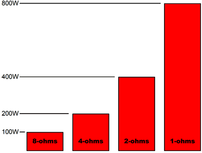
In contrast, solid-state power amplifiers are usually voltage-limited. A typical solid-state power amplifier can deliver great torrents of fuse-popping current into a dead short. Voltage peaks, in contrast, are truncated by the amplifier's fairly low power-supply rail voltages, which are usually between +/-25Vdc to +/-70Vdc. If the typical solid-state power amplifier held an output transformer, however, two results would obtain: it would cost much, much more and it would deliver more power. The first result is obvious, as copper and high-quality iron are not cheap and moving heavy amplifiers around the globe is expensive. The second result is not so obvious. One proof for the increased power is that a typical solid-state power amplifier will put more wattage into a 4-ohm load than an 8-ohm load. Indeed, many high-end, solid-state power amplifiers proudly state that they can put out monstrous amounts of power into 2-ohm or 1-ohm loads. Well, if these power amplifiers sported output transformers, they could deliver that same monster amount of power into an 8-ohm loudspeaker. Alas, although a few solid-state power amplifiers do use output transformers, this inclusion of iron will never become a trend in solid-state amplifier design, as even the lowly heatsink is deemed too expensive and heavy, which make class-D amplifiers all the more attractive to audio companies; ideally, as they see it, a power amplifier should be no larger than a pack of cigarettes. At a CES show, I saw what looked like a typical high-end, solid-state, audio power amplifier, replete with the thick aluminum faceplate and the two flanking large heatsinks and a many-digit price tag. So? This amplifier held a class-D power amplifier, which occupied a small PCB at the chassis' cavernous center. In other words, the heat sinks attached to nothing other than the air within the enclosure. When questioned about this interesting design feature, the poor company representative looked ill at ease. He explained that the heat sinks were largely gratuitous, although the convection-driven air currents within the chassis would deposit some heat on the heat sinks, but they were sadly necessary, as they were what an audiophile expected a power amplifier to look like. Although output transformers for solid-state amplifier will remain rare, there is, however, a simple trick to get more of the latent power out of a solid-state power amplifier: run the amplifier differentially. For example, if a solid-state power amplifier can put out 100W into 8-ohm loads and 200W into 4-ohm loads, then if we run the two of these amplifiers differentially with an 8-ohm load, the loudspeaker collects 400W, not 200W. How is this possible? How can two 100W amplifiers deliver 400W?
Yes, it does seem paradoxical, but the extraction of extra power does not break any laws of physics, as it results from a better load-matching for the amplifiers. In other words, if the 100w solid-state amplifiers had held output transformers, then they could have put out 200W into 8-ohm loads. But they didn't, so the differential opposition of the two amplifiers made the 8-ohm load effectively appear as a 4-ohm load to each power amplifier, allowing each to deliver 200W. If this same solid-state power amplifier can deliver 400W into a 2-ohm load, then the differential setup would deliver 800W into a 4-ohm loudspeaker. It isn't magic, just math.
The math, however, can get tricky. For example, often the specification for a solid-state power amplifier are not so linear, as the nominally 100W amplifier may only put out 160W into a 4-ohm loudspeaker, not the expected 200W. Where did the missing 40W go? A 4-ohm load sees the same voltage swings as the 8-ohm load and it draws twice the current that the 8-ohm load would. Well, that doubled current draw can probably be sustained for brief periods, so the amplifier does indeed put out peaks of 200W into a 4-ohm load. But long, sustained sine waves will reduce the power deliver into 4-oh loads to 160W, as the power transformer's own internal DC resistance against the doubled current draw will collapse the rail voltages to the point where the same output voltage swings can no longer be sustained, so the maximum power output drops. If this amplifier were used differentially with an 8-ohm load, the maximum power that could be delivered would be 320W. Beyond increased power, the differential driving of the loudspeaker offers some advantages. For example, the amplifier's slew-rate is effectively doubled, as twice the voltage rise can be achieved in the same amount of time; at the same time, it must be admitted, the damping factor will be halved, as the output impedance will double. In addition, if the two amplifiers share the same power supply, as one power amplifier swing positively, the other swings negatively, so both the positive and negative power-supply rails are dragged down equally. Moreover, each speaker cable lead will see its own capacitance-decoupling network, which could prevent RFI from sneaking in the power amplifier through its grounded output, as there is no grounded output, for each output terminal is actively driven.
Lastly, if the differential setup is carefully laid out, common-mode signals are largely rejected. Thus, if the signal source is contaminated with common-mode, i.e. shared, power-supply noises and RFI, then the differential power amplifier will drop this contamination from its amplification; and even if it did pass it along, the errant signals would be in phase and common to both outputs, so the loudspeaker could not "see" them. If you haven't gathered by all this that I quite like the differential arrangement, I will state my admiration for it now. It's groovy. (No doubt that was my first use of the word "groovy" here and equally no doubt it will be my last.) Okay, the simplest power-amplifier booster is the use of a secondary identical solid-state power amplifier in a differential arrangement with an 8-ohm loudspeaker. If mono amplifiers are used, four will be needed for stereo; if stereo amplifiers are used, two. I don't recommend this approach if your loudspeakers are 4-ohm units or if their impedance falls too low. The next question is Where does the balanced, the differential, input signal come from? Some line-stage amplifiers and most DACs offer a balanced output that is seldom used. Or a center-tapped, signal-isolation transformer can be used. Yes, each power amplifier will see half the input signal, but that works out well, as the effective gain of the differential setup is twice that of a single power amplifier. In other words, no change in volume will occur. A third approach is to use an active phase splitter circuit to create the needed two phased balanced output signals. With either OpAmps or tubes, this is fairly easy. Of course, you know my preference. (I should offer a simple unity-gain phase splitter PCB.)
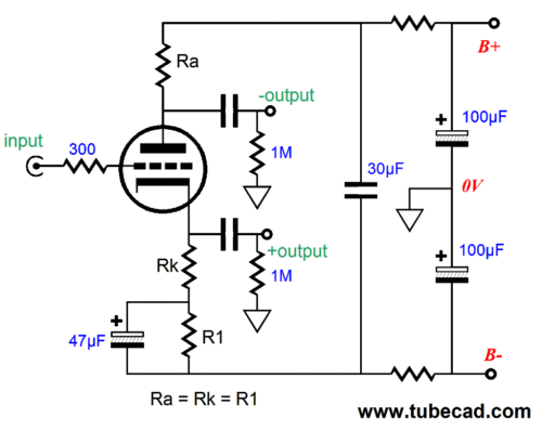
The assumption behind the above circuit is that the bipolar power supply develops equal but out-of-phase power-supply noise on both rails, which the spilt-load phase splitter exploits to null the noise from its two outputs. See Blog Number 196 for more details. For most stereo power amplifiers, the above circuit would work well, delivering a two-phased, balanced input signal. But with some power amplifiers, a bit more is needed.
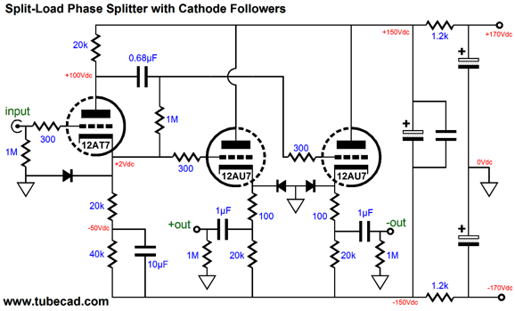
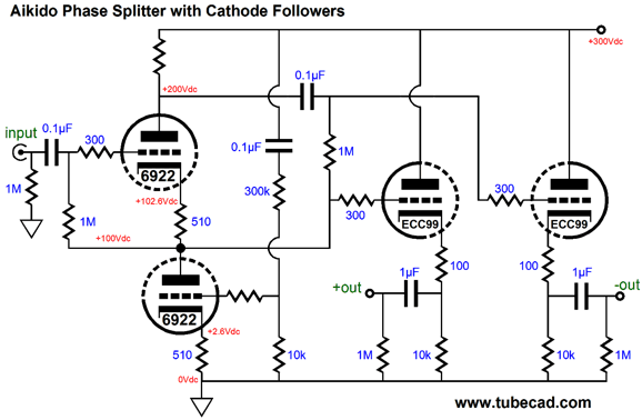
The above circuit may look excessively complex, as a simple split-load phase splitter could be used instead. But the above circuit embodies my prejudices, such as giving the sole task of splitting the phase to the split-load phase splitter and giving the job of driving the outputs to the two cathode followers. It also incorporates my signature power-supply noise canceling techniques and safety diodes that protect the tubes at turn-on, when the cathodes are cold and not emitting, when the grid voltage could be hundreds of volts more positive than the cathodes. The 12AT7's high amplification factor (mu) delivers a gain only slightly less than unity and the 12AU7s provide a fairly low output impedance. (If a more robust output is needed, say for driving 600-ohm loads or high-impedance headphones differentially, the ECC99 is a good choice.) Alternatively, if bipolar power supplies are not your thing, the following circuit makes use of a mono-polar power supply and my Aikido phase-splitter circuit.
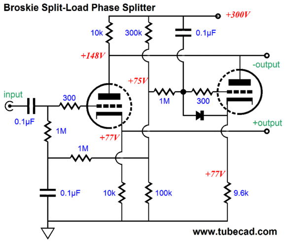
The big problem with the split-load phase splitter is the dissimilar output impedances, but its dismal PSRR from the output at its plate. The Aikido phase-splitter circuit uses the bottom triode both as a cathode resistor replacement and as a means of nulling the power-supply noise at the phase splitter's plate. The two cathode followers see equally quiet input signals as a result. Another possibility is the Broskie split-load phase splitter, which uses another triode to null the huge amount of power-supply noise from the inverting output.
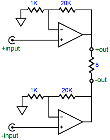
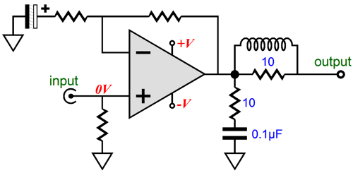
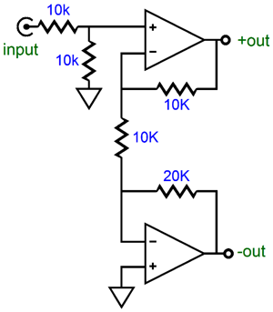
On the other hand, an OpAmp-based phase splitter is easy enough. Two OpAmps and few resistors are needed.
The two-resistor voltage divider at this phase splitter's input is not strictly necessary, but it does undo the gain of 2 that the OpAmps develop. Of course, discrete FETs or transistors could be used to build a solid-state phase splitter, but the OpAmp approach is certainly much easier. In addition, some OpAmps sound surprisingly good, such as the OPA2107, which I am quite partial to, finding it almost tube like. Of course, a solid-state phase splitter can be made from discrete transistors and resistors, as shown below.
I quickly came up with this circuit, so I am sure a simpler or better phase splitter can be designed with transistors. Check out Blog Number 202 for some ideas on how a discrete solid-state phase splitter could be made.
Boosting Transformer-Coupled Power Amplifiers
In terms of output current, the same 4W of output obtains, with the 8-ohm load getting a peak of 1A; a 16-ohm load, 707mA; and a 4-ohm load, 1.414A.
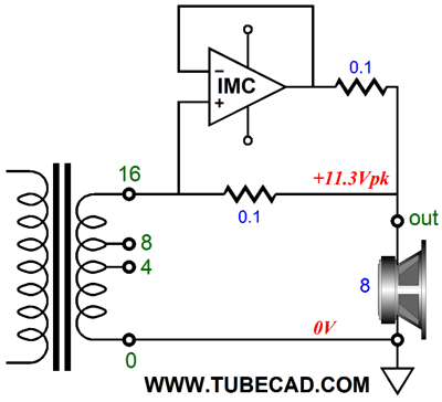
Note how as the load impedance goes up, so too the voltage, but the current goes down. Now, if the tube power amplifier could deliver more current at its 16-ohm tap, then an 8-ohm loudspeaker could be attached and it would see twice the power. If a 4-ohm speaker were attached to the 16-ohm tap, it would see four times the power. But as we are not allowed to break the laws of physics, such a dream is only suited to opium pipe smokers with excessive leisure time on their hands. But what if the required extra current could be found elsewhere, so the tube power amplifier was fooled into believing that it was attached to a 16-ohm speaker, not an 8-ohm or 4-ohm speaker?
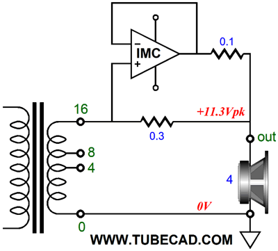
The tube amplifier still puts out the peak voltage of 11.3V and peak current of 707mA, but the loudspeaker draws 1.414A, so it secures 8W, not 4W. If a 4-ohm loudspeaker were used instead, the IMC must be adjusted to deliver enough current to make the 4-ohm load appear as a 16-ohm load.
What does "appear" mean in that last sentence? It means that as far as the amplifier is concerned the load must be a 16-ohm one, as that is the load-line imposed by it. As far as the 4-ohm loudspeaker is concerned it sees sufficient voltage and current to develop 16W, four times the amplifier's nominal 4W. No doubt, some are grumbling that 16W is still no big deal. Well, think about this: this power booster setup turned 4W into 16W, so it could also turn 40W into 160W.
Note how the IMC offers no signal gain and only augments the current flowing from the small power amplifier. Since the IMC's input signal is the small power amplifier's output voltage, I assume that the predominate sonic flavor will come from the small amplifier; nonetheless, we shouldn't expect no sonic contribution from the solid-state IMC, as no amplifier or unity-gain buffer is perfect. If we are lucky, the sonic blend will be more felicitous than either the small amplifier or the solid-state IMC alone—something of a half-way point that a few audio critics have argued as being the true ideal, neither pure tube or pure solid-state. Also note how the IMC's impedance ratio could easily be set with a switch with two positions: 8-ohm or 4-ohm.
Next Time
//JRB
|
I know that some readers wish to avoid Patreon, so here is a PayPal button instead. Thanks.
John Broskie
Kit User Guide PDFs
And
High-quality, double-sided, extra thick, 2-oz traces, plated-through holes, dual sets of resistor pads and pads for two coupling capacitors. Stereo and mono, octal and 9-pin printed circuit boards available.
Designed by John Broskie & Made in USA Aikido PCBs for as little as $24 http://glass-ware.stores.yahoo.net/
The Tube CAD Journal's first companion program, TCJ Filter Design lets you design a filter or crossover (passive, OpAmp or tube) without having to check out thick textbooks from the library and without having to breakout the scientific calculator. This program's goal is to provide a quick and easy display not only of the frequency response, but also of the resistor and capacitor values for a passive and active filters and crossovers. TCJ Filter Design is easy to use, but not lightweight, holding over 60 different filter topologies and up to four filter alignments: While the program's main concern is active filters, solid-state and tube, it also does passive filters. In fact, it can be used to calculate passive crossovers for use with speakers by entering 8 ohms as the terminating resistance. Click on the image below to see the full screen capture.
Tube crossovers are a major part of this program; both buffered and un-buffered tube based filters along with mono-polar and bipolar power supply topologies are covered. Available on a CD-ROM and a downloadable version (4 Megabytes). |
|||


| www.tubecad.com Copyright © 1999-2013 GlassWare All Rights Reserved |