| John Broskie's Guide to Tube Circuit Analysis & Design |
31 October 2022 Post Number 569
I am embarrassed to admit that I have yet to carve up a pumpkin with a triode symbol. Maybe next year.
300B-Based Augmented-Amplifier Ideas In truth, the output transistor's actual cost is much higher because of the need for a huge, heavy, and expensive heatsink, whereas output tubes do not require heatsinks. On the other hand, tubes wear out, whereas solid-state devices (usually) do not. If we factor all the costs and benefits, we must conclude a hybrid 300B power amplifier to be the most cost-effective choice. While saving money is always worthwhile, our goal is to preserve as much of the 300B's sonic signature as possible. In post 567, I showed a single-ended, transformer-coupled, 300B-based amplifier being augmented after the fact by a single-ended MOSFET-based unity-gain power buffer. This arrangement used an impedance-multiplier circuit (IMC) to boost twofold the 300B's power output.
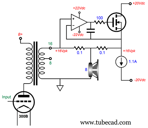
Well, what if we, instead, configured the 300B as a cathode follower and used a class-A, push-pull, unity-gain power buffer in the IMC?
No output transformer, which means OTL. Hooray!
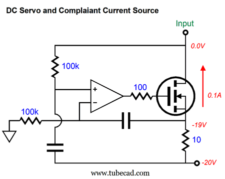
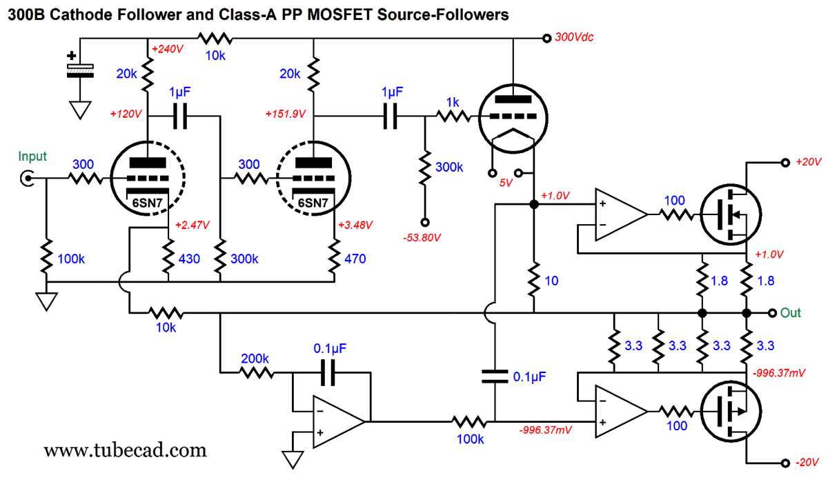
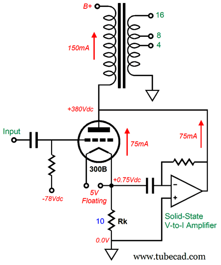
The 300B's cathode is loaded by a 100mA constant-current source, while its grid sees a negative bias voltage. The IMC impedance ratio is equal to (10 + 0.5)/0.5, or 21:1, so the 8-ohm loudspeaker appears as a 168-ohm load. Actually, it's closer to a 178-ohm load, as the 10-ohm series resistor's resistance must be added to the total. Note that the IMC falls out of the negative feedback loop. The constant-current source could be made from several L317-HV regulators placed in parallel. Alternatively, we could build a compliant constant-current source.
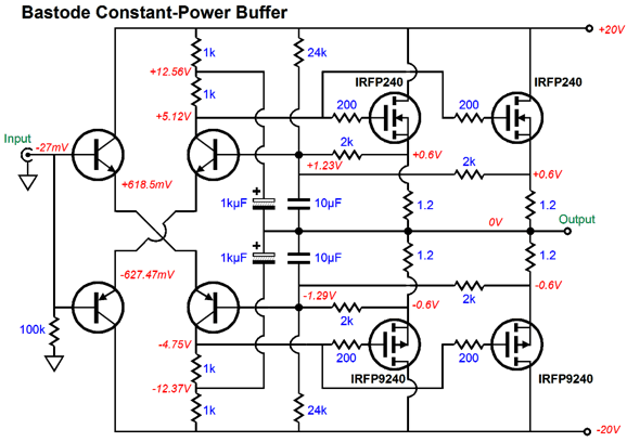
This circuit does not establish a fixed current flow; instead, it mimics the current flowing through the 300B. If the 300B draws 90mA, rather than 100mA, the circuit will draw 90mA as well. The circuit does, however, seek to banish a DC offset at the 300B's cathode, while presenting an extremely high impedance to the cathode, much as a true current regulator (CCS) would. This circuit works well to avoid start-up voltage bumps at the output. The 10k negative feedback resistor allows a global feedback loop to further lower the 300B-based cathode follower's output impedance. The class-A amplifier, push-pull unity-gain power buffer needs to idle at 1A, so 2A peak current swings can be delivered into the loudspeaker, which would develop 16W into an 8-ohm load. One possible design is found in post 352.
Each power MOSFET must dissipate 10W at idle. Since the buffer runs in strict class-A, the output stage actually cools as it delivers power into the loudspeaker. Another possible circuit design is from post 557.
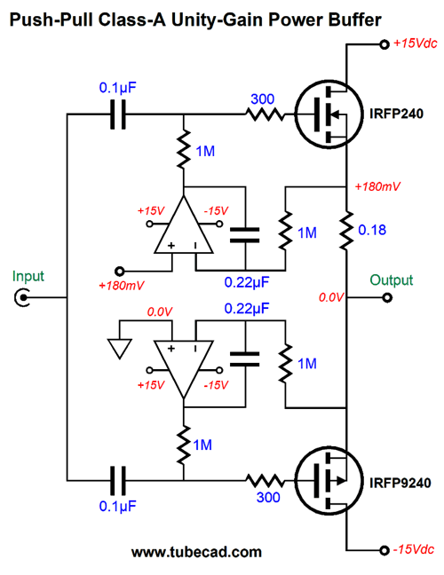
Many fewer parts are needed, as the OpAmps do all the housekeeping. The bipolar power supply voltage must be increased to +/-20Vdc or so. In addition, the number of MOSFETs should be doubled. The OpAmps set the idle current and eliminate DC offset voltages, but they do not otherwise control the MOSFET's output. In other words, this power buffer relies entirely on degenerative negative feedback inherent in the source follower operation to produce a clean output and a low output impedance. If we want to include the MOSFET's AC output in the OpAmp negative feedback loops, we need to use the following topology from post 452.
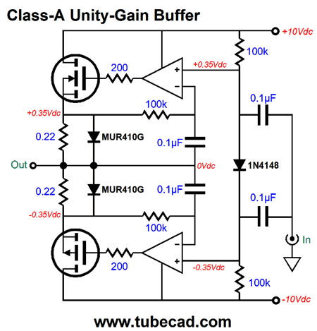
Effectively, we are looking at two class-A amplifiers in tandem, as each OpAmp controls only the output of its captured MOSFET. Well, what if we let the bottom MOSFET provide the 100mA of current flow into the 300B's cathode?
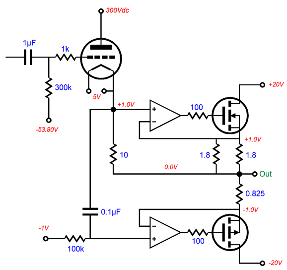
The two 1.8-ohm source resistors in parallel produce 0.9 ohms of resistance, which further in parallel with the 300B's 10-ohm cathode resistor results in 0.8257 ohms. In other words, the output centers on 0Vdc due to the equal current flow. Great, but where do we buy a 0.8257-ohm resistor? Well, a 0.82-ohm resistor comes close, but four 3.3-ohm resistors in parallel come even closer. Let's plug this output stage into the complete amplifier.
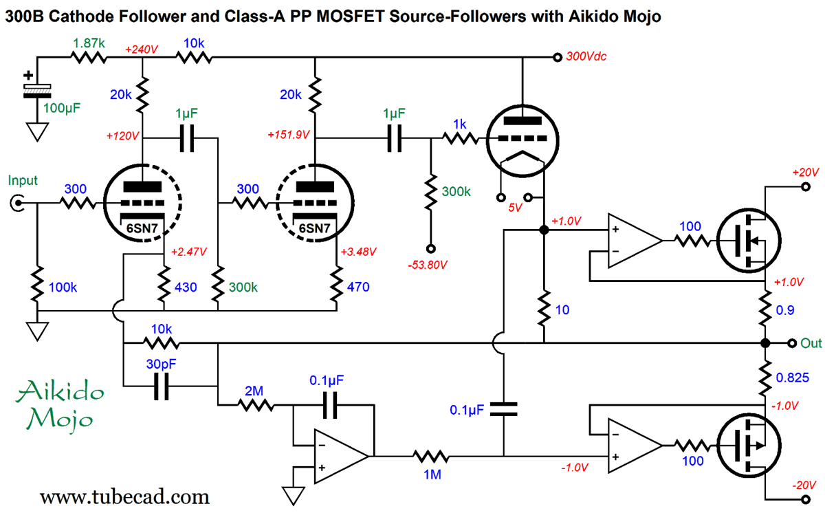
The leftmost OpAmp works as a DC servo that prevent any DC offset output at the output. If the 300B only draws 90mA, then the bottom P-MOSFET will draw 90mA as well, which erases any DC offset voltage at the output. In other words, the leftmost OpAmp does not set the output stage's idle current to a preset value. On the other hand, if we add another DC servo, one that works to establish a 1Vdc voltage drop across the 10-ohm cathode resistor by varying the 300B's grid voltage, then the output stage idle current will be set to 1.21A. Okay, let's inject some Aikido mojo.
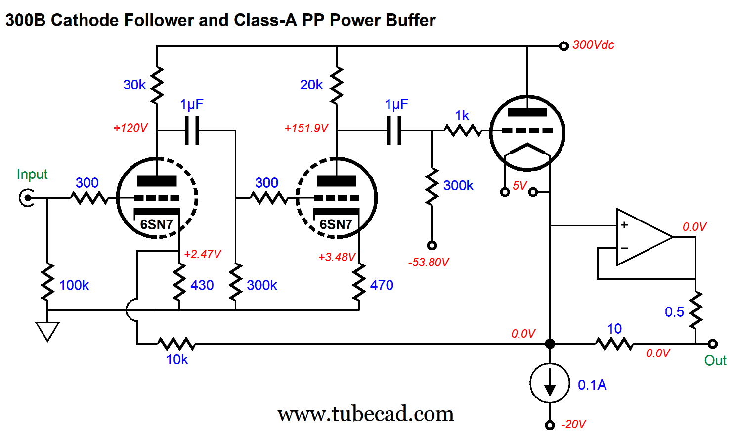
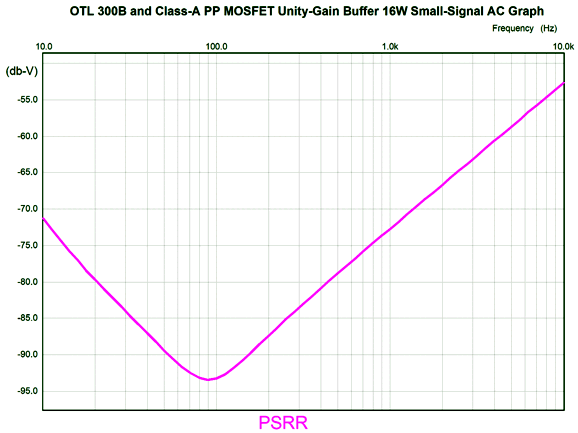
The 1.87k cynosure resistor leaks just enough B+ voltage ripple to create a power-supply-noise null at the output. How well does my cynosure trick work in this amplifier design? Without the resistor, the PSRR in SPICE simulations was -20dB at 100Hz; with the resistor, -93dB at 100Hz.
All the part values marked in green text are critical to achieving the wondrous PSRR. Sadly, this sort of dictating of precise part values runs counter to general tube practice, which deems part type and brand vastly more important than part value. Other than setting RIAA equalization networks or active crossovers, most enlightened solder slingers will throw in the part they believe sounds best—regardless of its incorrect value. Quoting myself from post 505:
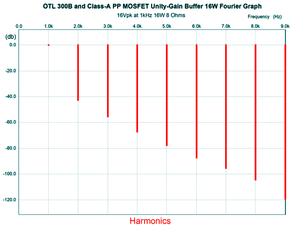
Here is a quick recap of how the amplifier works. The two 6SN7 triodes in cascade develop more than enough gain to drive the 300B-based cathode follower to 16V of peak output voltage swing, which the IMC helps along sufficiently to deliver 16Vpk into a an 8-ohm load, thereby producing 16W of power output. The amplifier's excess gain is then used to drive the negative feedback loop and reduce the amplifier's final gain, distortion, and output impedance. An input signal of 0.97pk is enough to drive the amplifier to full output (16W). The distortion at full output is about 1% and looks extremely single-ended.
The negative feedback loop encompasses the two MOSFETs and OpAmps. In SPICE simulations, the alternative arrangement of having the negative feedback loop terminate into the 300B's cathode didn't alter the amplifier's performance by much, so I abandoned this alternative approach. At 1W of output, the distortion falls by tenfold (20dB) and the same smooth falling away of higher harmonics obtains. The output impedance is about 0.9 ohms. The output bandwidth was ruler flat from 10Hz to 100kHz, with a clean rolloff above 400kHz.
Return of the Output Transformer
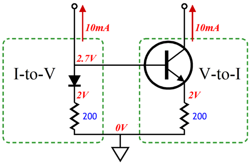
This is just the conceptual schematic. The idea behind it is that the 300B and the solid-state power amplifier will work in unison, both drawing the same current throughout, with the 300B in charge of the combined current flow. The AC signal appearing at the 300B's cathode resistor is in phase with the signal at its grid. The solid-state inverting power amplifier responds to the cathode voltage swings the same way that the 300B does to the signal at its grid: amplifying and inverting it at its plate. Think of this arrangement as an analog of the Darlington two-transistor topology, but with a triode cascading into a transistor. Actually, a better analogy would be that of a current-mirror circuit, where both active devices draw the same current.
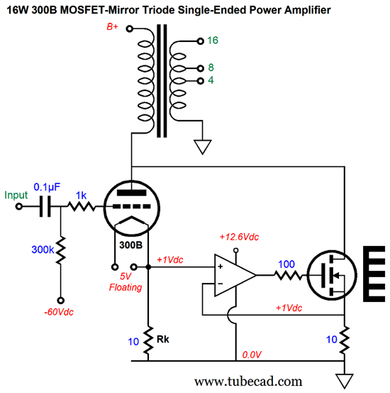
Of course, the output transformer would have to be capable of delivering twice the output power, but a 16W transformer doesn't cost all that much more than an 8W transformer; moreover, the slight increase in transformer cost is small in comparison to the cost of doubling up on 300B output tubes, especially if NOS WE 300B tubes are used. Another downside to this approach, in contrast to the IMC arrangement, is that it cannot be retrofitted to an existing 8W single-ended 300B-based power amplifier. The first idea to come to mind was the following.
The high-voltage power MOSFET mirrors the 300B's current flow exactly, as the OpAmp ensures that the MOSFET's 10-ohm source sees the same AC and DC voltage across its leads as does the 300B's 10-ohm cathode resistor. If the 300B ceases to conduct, so, too, the power MOSFET. If the 300B doubles its current conduction, so, too, the power MOSFET. Normally, the MOSFET drain impedance is super high, but in this circuit it mirrors the 300B's plate resistance, as the 300B is in control of the MOSFET's current conduction. In other words, the 300B and the MOSFET behave in the same way that two 300B tubes in parallel would. If the inclusion of the OpAmp bothers you, we can replace it with half of the transistor diamond circuit.
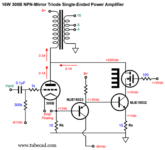
The PNP transistor in cascade with the NPN transistor works a unity-gain buffer with nearly the same AC and DC input and output voltage. The high-voltage power MOSFET creates a cascode circuit with the NPN transistor below it. Indeed, we could further cascode another MOSFET atop it. On the other hand, we can replace the MOSFET with a power pentode, such as the KT88.
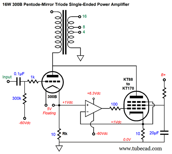
A high-voltage OpAmp, such as the ADA4700-1 or LTC6090 or OPA445, drives the pentode's grid and imposes the strict mirroring action on the pentode. Imagine four KT88s and one 300B configured in this current-mirror topology delivering 40W of 300B single-ended sonic glory. The output transformer's winding ratio for 8-ohm loads would be a low 6.33:1, which implies a primary impedance of only 320 ohms. If the inclusion of the OpAmp bothers you, you could replace the solid-state OpAmp with a tube-based OpAmp.
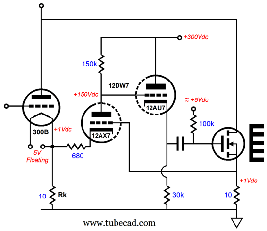
The 12DW7 twin-triode tube holds dissimilar triodes, one 12AX7 and one 12AU7 type. The 12AX7 input triode is configured in the grounded-grid amplifier topology, where the input signal is at its cathode, not its grid. The grid is used as a negative feedback input in this circuit. The 12AU7 triode is configured as a cathode follower. The grounded-grid amplifier does not invert its input signal at its output, so the signal present on the 300B's cathode resistor will be superimposed upon the N-MOSFET's source resistor. The 12AX7 triode compares the two signals and adjusts its plate voltage to bring the two in line with each other. Negative feedback, in a nutshell. Missing from the schematic are all the grid-stopper resistors and the protective diode from 150k to the 30k resistor—all were elided for conceptual clarity. The required bias voltage for the MOSFET's gate could be adjusted with a potentiometer. A better approach would be to retain an OpAmp for auto-biasing the MOSFET with a DC servo.
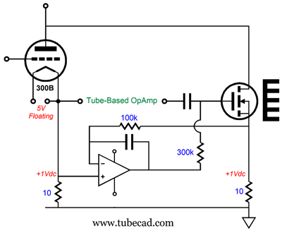
The OpAmp strives to maintain the same DC voltage drop across both 10-ohm resistors. Interestingly, the OpAmp's output will follow the signal at the cathode resistor, including the AC signal. Does this mean that the tube-based OpAmp is being bypassed? No, as the 300k gate resistor forms a two-resistor voltage divider with the cathode follower's output impedance (about 300 ohms), so the tube-based OpAmp over powers the solid-state OpAmp by about a thousand fold in AC terms. Another way to double a 300B output tube's power output is to go push-pull with a solid-state device.
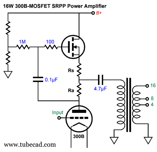
This is a hybrid SRPP topology, with the 300B's plate resistor acting as a phase splitter for the high-voltage MOSFET's gate. With some tweaking of the plate resistor and source resistor values, we could achieve equal and opposite current swings from the two dissimilar output devices. The output transformer no longer needs an air-gap, so a regular push-pull output transformer could be used. Unlike two 300B tubes in a similar SRPP configuration, the B+ voltage does not need to be twice that of a 300B single-ended power amplifier, as the MOSFET does not require a large chunk of high-voltage padding the way a triode does. In other words, a B+ voltage of only 560Vdc would be probably sufficient. Yes, this is arrangement is much like the (if not functionally identical to) "steered constant-current source" faux single-ended amplifier topology.
300B and MOSFET Working in Tandem
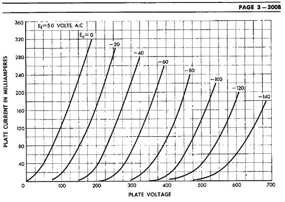
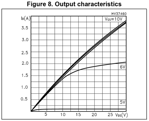
To find the plate-overhead voltage we simply double the triode's idle current and inspect the triode's plate curve's 0V grid plotline's intersection with the doubled current. For example, with a 300B idling at 100mA, the 0V grid line intersects 200mA at about 137V. If we expect a plate voltage swing of +/-160V, then the B+ voltage must exceed 137V + 160V, or 297Vdc. Now, let's contrast this with a high-voltage MOSFET, the STW3N150, which is a 1500V, 140W N-MOSFET.
We see that we only need a few volts of overhead voltage to obtain 200mA of current flow. In other words, the power MOSFET could deliver the same amount of output power as the 300B with a B+ voltage about half as high as the 300B's B+ voltage. This means that letting the 300B and the MOSFET share the same B+ voltage will entail a lot of wasted heat creation. Well, what if we ran two different B+ voltages?
The output transformer holds two separate primaries, each with the same number of turns of wire, thus the same reflected impedance. Each primary sees the same 100mA of idle current flow and the same peak current flow of 200mA and the same peak voltage swing of 160V, results in 16W of output power. At idle, the 300B dissipates 34W; the MOSFET, 16.5W, bringing in the output stage efficiency at about 32%. If two 300B output tubes had been used instead, the combined plate dissipation would have been 68W, so the output stage efficiency would have been only 24%. (These calculations do not include the power dissipated by the input stage and heater elements.)
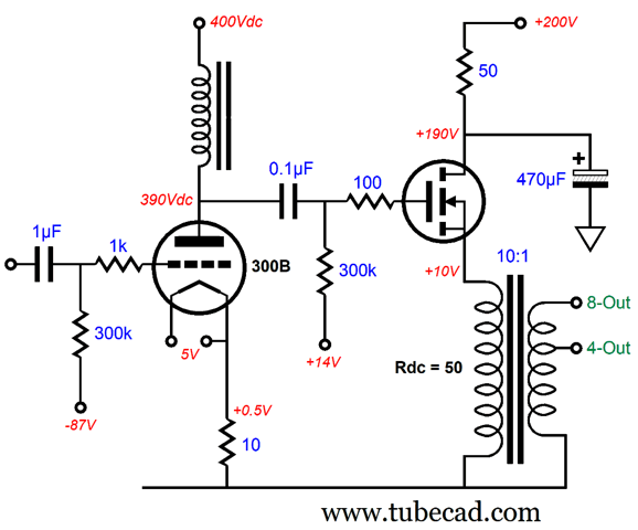
300B Qua Driver Stage
The 300B idles at only 50mA, so its dissipation is only 19.5W. The MOSFET idles at 200mA, so its dissipation is a toasty 36W. (In other words, we might have to double up on power MOSFETs.) The output transformer's winding ratio of 10:1 implies an impedance ratio of 100:1, so the 8-ohm load appears as 800 ohms on the primary. (The 4-ohm winding ratio would be 14.14:1, which also implies an 800-ohm primary impedance.) In order for the MOSFET to swing 160V peak, the 300B's plate will have to swing at least the same voltage. This should be no problem for the triode, as it is effectively loaded by constant-current source presenting a staggeringly high impedance, as inductor strives to maintain a constant flow of current through the 300B. in other words, the 300B is unburdened, so we can expect a gain equal to its amplification factor (mu), which is about 4. Well, to get 160V of peak plate voltage swing will need about 40V of peak grid-voltage swing. Which two 6SN7 triodes in cascade can easily deliver.
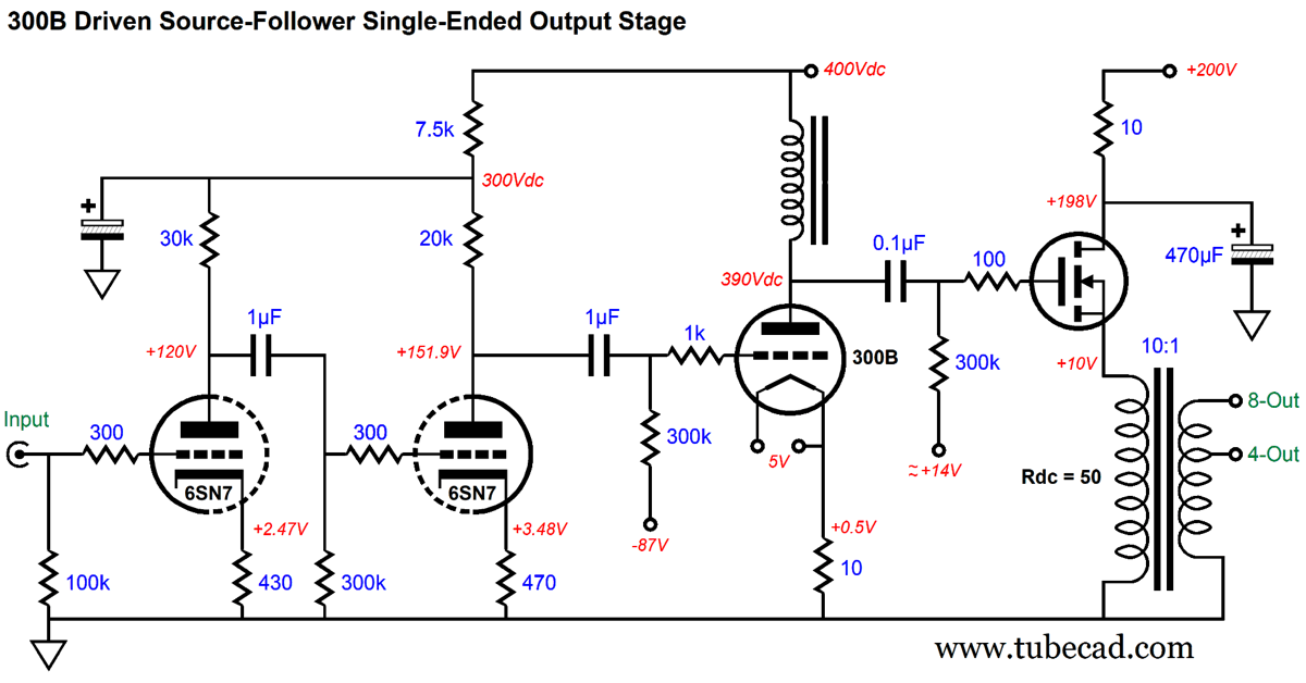
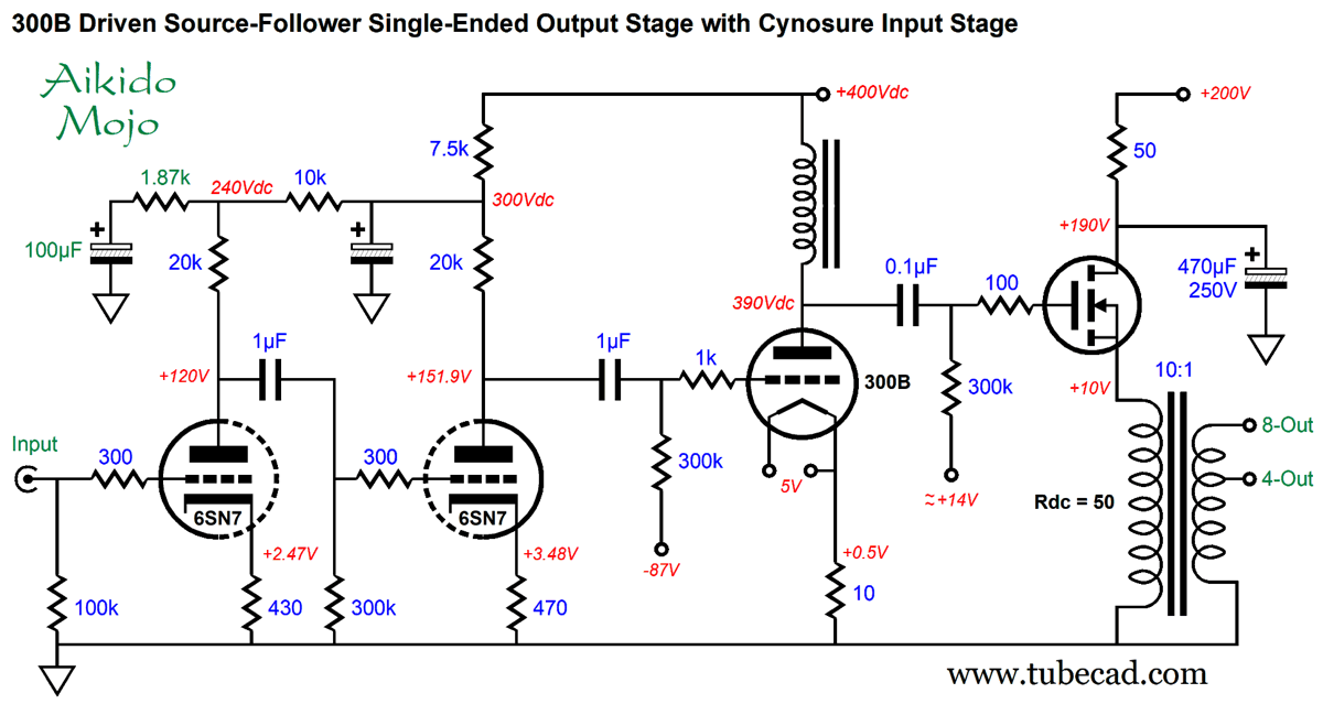
If anything, the two-triode cascade provides too much gain. We could reduce the gain by using a 12AU7 instead or by reducing the plate resistor values or by incorporating a negative feedback loop from the input triode's cathode to the second 6SN7's plate. One thing I would certainly want do is to add some Aikido mojo.
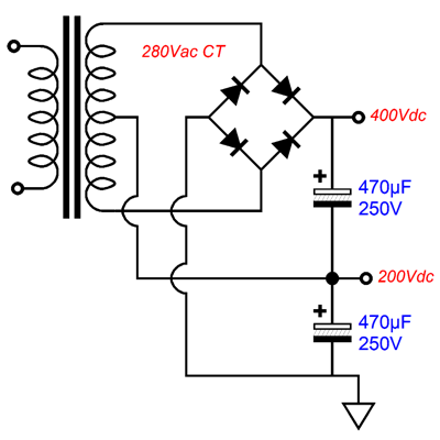
The 1.87k cynosure resistor inject a small amount of the B+ voltage noise into the right 6SN7 triode's grid, so a deep power-supply-noise null obtains. We needn't worry too much about the 300B, as the inductor shields the triode from the power-supply noise. We do, however, need to worry about the inductor's quality. A junk-box power supply choke will not cut it. The inductor must be built to the same high standard as the output transformer, with high-quality iron and careful winding. What would the power supply look like? Very simple indeed.
The two power-supply rail voltages are easy enough to create, as all we need is a center-tapped secondary.
Last 300B-Based Idea
The 300Bs would drive headphones and two solid-state power buffers would drive loudspeakers. This idea ran into a conceptual snag, as I could not think of an elegant way to inject some Aikido mojo to improve the PSRR. The solution came to me in the form of standing the 300B stage on its head.
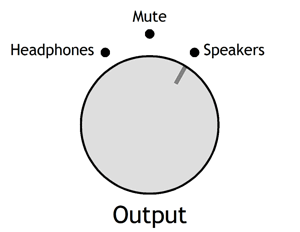
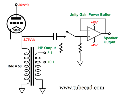
The 300B is now configured as a cathode follower and the output transformer is located at its cathode. When we listen to headphones, the stereo power buffer is disengaged. When we listen to loudspeakers, it's engaged, while the headphones are disconnected. Once again, the 300B works into a high-impedance load. With a winding ratio of 10:1 for low-impedance headphones, the 300B cathode must swing 10V to deliver 1V of output signal. The impedance ratio is equal to the square of the winding ratio, so 32-ohm headphones will reflect to the primary as a 3200-ohm load. I imagine that 4Vpk will prove thunderously loud for most low-impedance headphones, so the 300B need only swing 40Vpk, which in turn means that the input stage must deliver at least that much gain, i.e. 1:40.
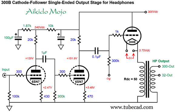
Here we see a 6SN7 configured in the same two grounded-cathode amplifier cascade as in the previous design. This may seem odd at first, as the previous design required the 300B to develop 160V peak voltage swings, whereas this circuit only requires 40V peak swings. The difference is that the cathode follower does not produce any signal gain; in fact, it falls a tad below unity-gain. As compensation of sorts, the cathode follower delivers far lower distortion and output impedance. By the way, since the unity-gain power buffer will see the 40V of peak voltage swing from the 300B's cathode, how much power does that equal with 8-ohm loudspeakers? The answer: 100W, as 40V² / (8ohms x 2) = 100W.
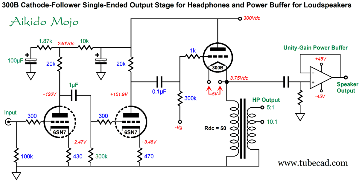
The power buffer runs off a +/-45Vdc bipolar power supply. I would use a regulated B+ voltage for the 300B and the input and driver stages. By the way, the output transformer allows for easy balanced output for the headphones, as we need only break the connection to ground. (The output transformer also allows for easy phase reversal for the headphones, as we need only flip the secondaries, assuming balanced output.) This is a project that I would love to build. The only difficult part would be locating the output transformers and designing a high-quality unity-gain power buffer. Next time.
Music Recommendation: Qobuz What I didn't like was that, like Tidal and Amazon Music, Qobuz has no idea what classical music is. Composers are not performers; symphony movements are not songs; compositions are critical; classical sub-genres are numerous; the conductor is important, as can be the orchestra or ensemble; eras of musical creation cannot be ignored; recording labels figure much more importantly than with pop music. If I type in "Beethoven," the app should list his compositions first, not the huge array of album covers. Once I pick a composition, I should be able to refine the search further by selecting conductor or recording label or featured soloist. Qobuz isn't close to being perfect, but it beats its compitition when it comes to classical music. Amazon, however,wins the content battle. Here is an example: I went searching at Qobuz for the Danish blues-man, Thorbjørn Risager. I was happy to find 10 albums. When I made the same search at Amazon Music, I found 28 albums. But the big bummer for me was that that music stream hick-upped more often than was bearable on the high-res music (24-bit, 192kHz), as the interruption was not silence, but garbled sound. (I listen to headphones primarily, so any disturbance is disturbing in the extreme.) To test if it was my WiFi fault (fiber optic), I fired up Amazon music and heard nothing go wrong (once again, with 24-bit, 192kHz). I also noticed that that if I used another program, such as MS Word or my graphics programs, the small glitches resulted with Qobuz. I tried running the app as an administrator with no change. I have yet to hunt down how to prioritize the digital stream to the app. I did increase the time buffer setting, but it didn't seem to make any difference whatsoever. What will happen when my free month ends? I will sign up, working on the assumption that Qobuz holds great promise and probably is undergoing some growing pains.
//JRB
Did you enjoy my post? Do you want to see me make it to post 1,000? If so, think about supporting me at Patreon.
User Guides for GlassWare Software
For those of you who still have old computers running Windows XP (32-bit) or any other Windows 32-bit OS, I have setup the download availability of my old old standards: Tube CAD, SE Amp CAD, and Audio Gadgets. The downloads are at the GlassWare-Yahoo store and the price is only $9.95 for each program. http://glass-ware.stores.yahoo.net/adsoffromgla.html So many have asked that I had to do it. WARNING: THESE THREE PROGRAMS WILL NOT RUN UNDER VISTA 64-Bit or WINDOWS 7, 8, and 10 if the OS is not 32-bit or if it is a 64-bit OS. I do plan on remaking all of these programs into 64-bit versions, but it will be a huge ordeal, as programming requires vast chunks of noise-free time, something very rare with children running about. Ideally, I would love to come out with versions that run on iPads and Android-OS tablets.
|
I know that some readers wish to avoid Patreon, so here is a PayPal button instead. Thanks.
John Broskie
John Gives
Special Thanks to the Special 80 To all my patrons, all 80 of them, thank you all again. I want to especially thank
All of your support makes a big difference. I would love to arrive at the point where creating my posts was my top priority of the day, not something that I have to steal time from other obligations to do. The more support I get, the higher up these posts move up in deserving attention.
If you have been reading my posts, you know that my lifetime goal is reaching post number one thousand. I have 431 more to go. My second goal was to gather 1,000 patrons. Well, that no longer seems possible to me, so I will shoot for a mighty 100 instead. Thus, I have just 20 patrons to go. Help me get there. Thanks.
Support the Tube CAD Journal & get an extremely powerful push-pull tube-amplifier simulator for TCJ Push-Pull Calculator
TCJ PPC Version 2 Improvements Rebuilt simulation engine *User definable
Download or CD ROM For more information, please visit our Web site : To purchase, please visit our Yahoo Store: |
|||


| www.tubecad.com Copyright © 1999-2021 GlassWare All Rights Reserved |