| John Broskie's Guide to Tube Circuit Analysis & Design |
06 August 2016
Pentodes and Aikido Mojo
(I just queried Google with “300b + tubecad.com” and 17,800 results came up. If only one tenth of those results is actually found on my site, the number is still a tad higher than never; indeed, it might be even over “so rare” in quantity.)
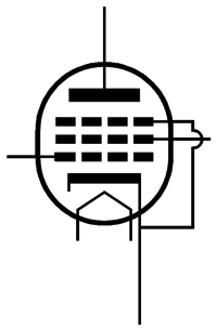
The pentode is 9o years old now, having been invented in 1926. A pentode holds three grids: the control grid, the screen grid, and the suppressor grid, which works to inhibit secondary emission.
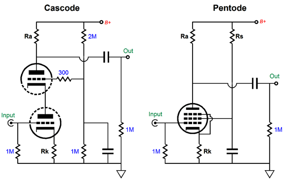
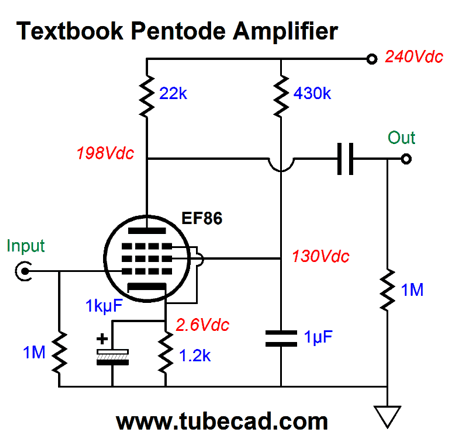
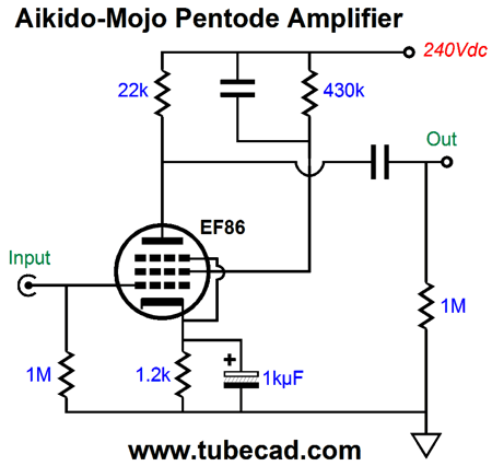
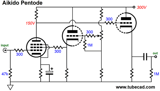
Triodes in cascode are similar to a single pentode. The cascode circuit sought to achieve the gain of a pentode but without the pentode’s noise, noise due to random shifts in the flow of electrons from the cathode up to the plate as the electrons move about the screen grid (grid-2) before hitting the plate, creating the famous pentode hiss. (In reality, the difference between a good audio pentode, i.e. a sharp-cutoff pentode, and a high-mu, high rp triode, such as the 12AX7 and 5751 is not that great. More often, the pentode’s greater offence is increased microphonics.) Since triodes in cascode are similar to a single pentode, we can apply similar Aikido mojo techniques to enhance the pentode’s PSRR. For example, what follows is a textbook pentode circuit—in layout if not in part values. (Most often, a far larger plate resistor value would have been used.)
With an EF86, a nice-sounding pentode by the way, about 97% of the power-supply noise leaks out the circuit’s output, a PSRR figure of only -0.264dB.
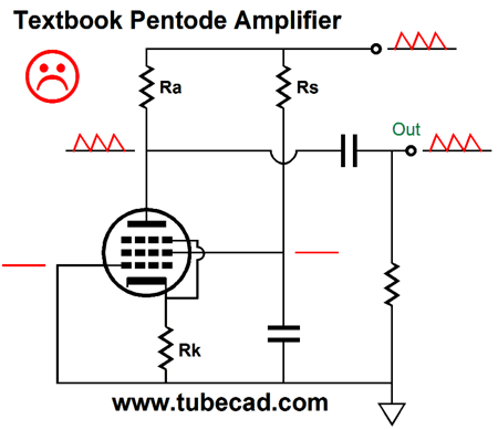
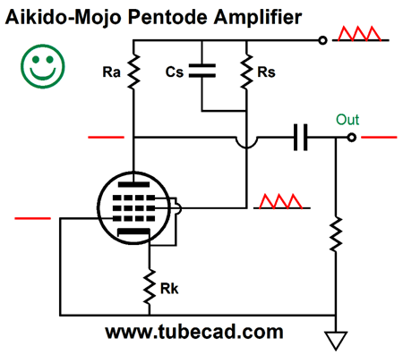
If we rearrange the placement of the screen-shunting capacitor, as in the following schematic, we accomplish a much better PSRR by creating some Aikido mojo in the move.
A pentode holds many transconductances: the control grid, the cathode, and the screen-grid transconductances. The screen’s transconductance will always prove lower than the grid’s, much in the same way that in a cascode the top triode’s grid offers less transconductance than the bottom triode’s grid. Nonetheless, as long as we set the plate resistor’s value to the reciprocal of the screen’s transconductance (1/gmG2), we will achieve an excellent PSRR from the pentode circuit, as our delivering all the power-supply noise to the screen grid will prompt an inverted power-supply noise at the plate equal in amplitude to the noise at the B+ connection, which results in the power-supply-noise null, as 1 - 1 equals 0. Unfortunately, most pentode data sheets fail to provide the screen-grid’s transconductance. In this example, SPICE simulations revealed an EF86 screen transconductance of 0.04545mA/V, whose inverse is 22k.
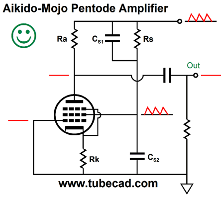
The above circuit achieves a gain of +30dB and a PSRR figure below -40dB. Mind you, if the cathode resistor is not bypassed, then the deal is off, as the gain will drop and the PSRR will worsen. Speaking of deals, no doubt that some are wondering if I haven’t improved a pentode’s PSRR at the expense of its gain. In this example, perhaps I have, but then we might be happy with a gain of +30dB. In those cases wherein we seek as much signal gain as we can get, we must employ a variation on the pentode Aikido mojo. The larger the plate resistor value, the more gain the pentode realizes. If the plate resistor value exceeds the inverse of the screen transconductance, then the screen grid must see a smaller portion of the power-supply noise. For example, if we use a 47k plate resistor with the EF86, then the screen grid must see 22k/47k as much of the power-supply noise.
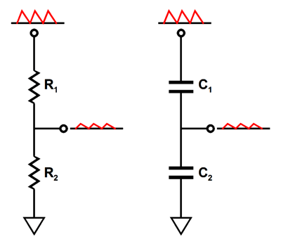
AC signal voltage dividers can be made from two resistors or two inductors or two capacitors. Two 1µF capacitors in series define an AC voltage divider of 50%, just as two 1k resistors would.
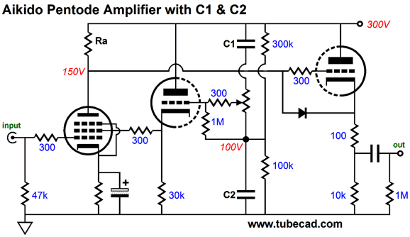
But if we place a 3µF capacitor atop a 1µF capacitor, what will the AC signal division be? If you guessed 25%, then you need to review your electronics textbooks, as capacitors differ from resistors in many striking ways.* For example, two 1µF capacitors in parallel create a 2µF capacitance, whereas two 1k resistors in parallel create a 500-ohm resistance. The larger the capacitance, the lower the capacitor’s impedance. Thus, a 3µF capacitor atop a 1µF capacitor results in 75% of the AC signal appearing at the nexus between capacitors. The formula for two-resistor voltage dividers is: Ratio = R2/(R1 + R2) whereas the formula for two capacitors is: Ratio = C2/(C1 + C2) Thus, if we set the ratio to 22k/47k, or 0.468, and solve for C1, we get: C1 = C2Ratio/(1 - Ratio), or 0.87. In other words, to get C1’s value we multiply C2 by 0.87. For example, if C2 equals 10µF, then C1 should equal 8.7µF. Mind you this is are starting point, not necessarily our ending point. I ran some SPICE simulations on the following circuit and I found that 8.2µF worked best. Why the discrepancy? Much like a triode, a pentode’s screen transconductance is not a constant such as its weight or height, as it varies with changes in screen current and voltage. In short, expect to experiment. Moreover, a decent scope will prove a godsend. Before leaving this topic, I must point out that I have brought the Aikido mojo to the pentode before; for example, see blog number 247, where you will find the following circuit.
A potentiometer replaces doing math and trial-and-error part replacement. Capacitors C1 & C2 might still be needed, which I would do as follows.
The screen grid sees a constant DC voltage as the potentiometer is twisted. The added diode protects the output cathode follower at start-up.
Constant-Power Class-A Power Buffer
The two bastode differential amplifiers replace the more conventional differential pairs of NPN & NPN and PNP & PNP transistors, which would look something like the following.
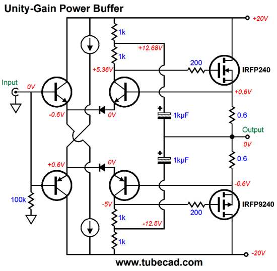
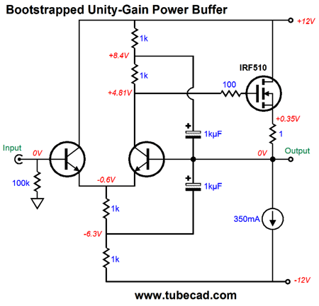
No doubt that many feel that this schematic returns us to the planet Earth, no more bastodes, no more head scratching, just plain, old, conservative, textbook-approved differential amplifiers. True, such a reader would prefer no diodes and would welcome two current mirrors in place of the bootstrapped collector resistors, but at least this version looks normal. This power buffer runs in class-A and offers no constant-power feature. The NPN-based differential amplifier controls the N-channel MOSFET (IRFP240), while the PNP-based differential amplifier controls the P-channel MOSFET (IRFP9240). The added diodes forced a 0.6V voltage drop, which means that the right side of the differential amplifiers bases must see that same voltage drop, which allows us to auto-bias the output stage. The bootstrapped collector resistors may look clunky, but they allow the power buffer to swing much larger output voltage swings. How so? The power MOSFETs require a large turn-on voltage, about 5V, which would normally restrict the buffers output to the rail voltage minus about 6V. In other words, with +/-20V power-supply rails, we could get only about +/-14Vpk swings from the output before the differential input stage hit the voltage limits imposed by the MOSFET's gate voltages. With the bootstrapped collector resistors, the output stage can swing past those limits. Here is a simple, single-ended, unity-gain power buffer that uses dual bootstrapping.
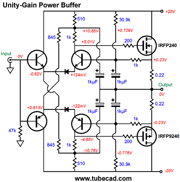
Super simple, super effective. The bootstrapping allows the output to swing +/-10Vpk into a 32-ohm load, i.e. a headphone driver, and it allows us to do away with the constant-current-source at the differential amplifier's tail. The downside to bootstrapping is that it works best with music, especially music that varies in amplitude, not signal-generator sine waves that run continually, as the capacitors will tend to discharge after large sustained sine wave reproduction. (Actually, as long as the buffer runs within its class-A window of operation and does not clip, the bootstrapping will work flawlessly.) This circuit could be turned into a mighty 6W power buffer (an external hot tube line stage would serve as the gain stage) for driving efficient speakers by using the idle current to 1.3A and using a higher-wattage MOSFET, such as the IRFP240. Or, we could resort to push-pull class-A operation with the following circuit, which does exhibit constant-power operation.
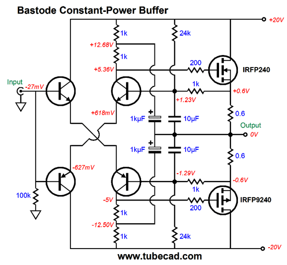
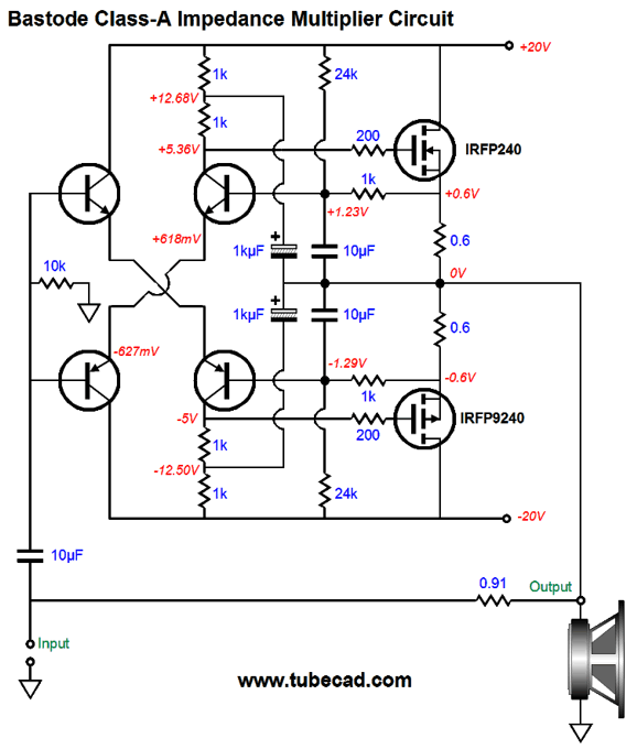
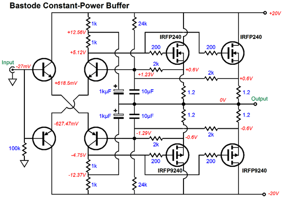
Note that the differential frontend uses no constant-current sources. The 1kµF capacitors that provide the AC feedback could be replaced with 10µF film capacitors. Let's return to bastodes and constant-power operation. At the time I created my bastode-based version, I realized that a change in power-supply rail voltages would result in a change in idle current. I quickly discerned that an increase in rail voltage would lower the idle current, while a decrease in rail voltage would raise the idle current—both of which were good results. Running strict class-A was essential and auto-biasing was a desirable feature. In addition, the large-valued source resistors would work well within the impedance-multiplier concept. Here is what I originally had in mind.
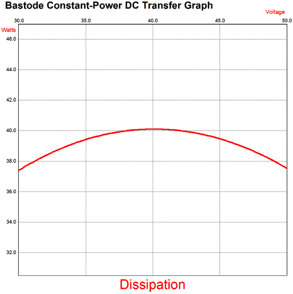
The two 0.6-ohm emitter resistors are effectively in parallel, so the buffer's output impedance is 0.3 ohms, which added to the 0.91-ohm resistor yields an impedance ratio of 4:1. In other words, an 8-ohm speaker appears as a 32-ohm load to the driving amplifier. Well, now that I am on my constant-power kick, I decided to reexamine the circuit more closely and determine the optimal resistor values to center the constant-power curve on the target +/-20V rail voltages.
Note that in this graph voltage refers to the sum of the negative and positive rail voltages. One fear I had was that even with the low 20V power-supply rails and the 20W of dissipation per power MOSFET that the heatsink would have too much heat to wick away per MOSFET. Thus, I redesigned the power buffer to use four MOSFETs. Same output power, same output impedance, same total heat dissipation, but each MOSFET sees a lower internal temperature.
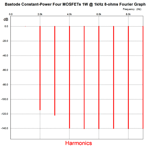
Note how we retained the two 24k resistors, but used four 2k resistors in place of the two 1k resistors. Each power MOSFET sees an idle current of 0.5A and the entire output stage must dissipate 40w of heat at idle. This means that the heatsink (per channel) must exhibit a thermal resistance below 0.8C/W. How well does this version perform in terms of distortion? Here is the SPICE results with 1 watt into 8 ohms at 1kHz.
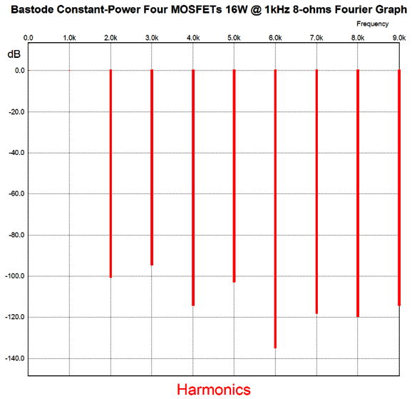
If the first watt is the most important watt, which I believe it is, this first watt is exceedingly fine. Note the single-ended look of the structure. Note that the THD is below 0.001%. Even if reality is ten times worse, the results would be 0.01%. Not bad. At full output, i.e. 16W, the harmonics structure looks more push-pull, but is still excellent.
*Positively Negative
//JRB
User Guides for GlassWare Software Since I am still getting e-mail asking how to buy these GlassWare software programs:
For those of you who still have old computers running Windows XP (32-bit) or any other Windows 32-bit OS, I have setup the download availability of my old old standards: Tube CAD, SE Amp CAD, and Audio Gadgets. The downloads are at the GlassWare-Yahoo store and the price is only $9.95 for each program. http://glass-ware.stores.yahoo.net/adsoffromgla.html So many have asked that I had to do it. WARNING: THESE THREE PROGRAMS WILL NOT RUN UNDER VISTA 64-Bit or WINDOWS 7 & 8 or any other 64-bit OS. One day, I do plan on remaking all of these programs into 64-bit versions, but it will be a huge ordeal, as programming requires vast chunks of noise-free time, something very rare with children running about. Ideally, I would love to come out with versions that run on iPads and Android-OS tablets.
//JRB |
Kit User Guide PDFs
And
High-quality, double-sided, extra thick, 2-oz traces, plated-through holes, dual sets of resistor pads and pads for two coupling capacitors. Stereo and mono, octal and 9-pin printed circuit boards available.
Designed by John Broskie & Made in USA Aikido PCBs for as little as $24 http://glass-ware.stores.yahoo.net/
The Tube CAD Journal's first companion program, TCJ Filter Design lets you design a filter or crossover (passive, OpAmp or tube) without having to check out thick textbooks from the library and without having to breakout the scientific calculator. This program's goal is to provide a quick and easy display not only of the frequency response, but also of the resistor and capacitor values for a passive and active filters and crossovers. TCJ Filter Design is easy to use, but not lightweight, holding over 60 different filter topologies and up to four filter alignments: While the program's main concern is active filters, solid-state and tube, it also does passive filters. In fact, it can be used to calculate passive crossovers for use with speakers by entering 8 ohms as the terminating resistance. Click on the image below to see the full screen capture.
Tube crossovers are a major part of this program; both buffered and un-buffered tube based filters along with mono-polar and bipolar power supply topologies are covered. Available on a CD-ROM and a downloadable version (4 Megabytes). |
||


| www.tubecad.com Copyright © 1999-2016 GlassWare All Rights Reserved |