| John Broskie's Guide to Tube Circuit Analysis & Design |
15 May 2022 Post Number 557
Bascom King RIP
I heard panic and pain in his voice. My friend had called me to bemoan the unfolding catastrophe in Ukraine. The old saying that "the first casualty in war is The Truth" must now be amended with the subtraction of vacuum tubes. As a musician, his fear—never being able to re-tube his many guitar amplifiers—makes more sense than most can understand. His tube music amplifiers are musical instruments, just as much as are his guitars. Without them, his signature sound is dead. I pointed out that tubes are made in countries other than Russia. Well, he was better informed than me, as he knew all the existing tube-producing companies in the world. For example, he informed me that the plant in China had closed due to a fire and had never been rebuilt; besides, their tubes were not as good as the Russian-made tubes. What's the solution? Perhaps, some American billionaire will resurrect tube-production in North America. I long to see modern technology applied to tube production: for example, laser-cut grid frames, Japanese late-development TV-tube cathodes, 12SX7 plate treatments, precise robotic assembly, extra-hard vacuum pumps, metal or ceramic envelopes...
Solid-State Output Stages What starts? My mind. I ask myself What circuit could use a 12Vdc switching power supply that puts out 2A, then schematics fill a few sheets in my drawing sketch pad.
Since the switching power supplies usually deliver more current than voltage, headphone amplifiers and flea-power amplifiers for loudspeakers are the first to come to mind, as a phono preamp doesn't need amperes of current flow. (See post 549 for more examples of switching power supplies and audio projects.) At the same time, I have been thinking about a conversation I had with Richard Vandersteen at the last RMAF, which turned out to be the actual last RMAF ever, sadly. I held such mixed emotions over the demise of the RMAF back in last October. I didn't like the new venue for the event and I hated the hassle of driving to it. In addition, I had predicted the RMAF's death to several doubting friends, so I felt vindicated. The huge, exceptional, all-important BUT is that with the passing of the RMAF, I will not see so many of friends again. The list is not short. (I just might have to attend audio shows elsewhere.) Returning to Vandersteen, at the last RMAF, we were talking about solid-state power amplifier design and he informed me that he hates emitter resistors in the solid-state output stage, as they just get in the way, so he strives never to use them. He is not alone. The resistors waste potential output power and introduce parasitics, such as inductance and resistor non-linearity; they also burn off potential transconductance; in addition, they are large and cost far more than lower-power resistors. So why are they used universally? Two reasons come immediately to mind. The first is that we need some way to measure the current flow through the output stage, and the voltage drop across the emitter resistors reveals the current low, as the voltage drop divided by the resistor's resistance equals the current flow; i.e. I = V/R.
The second reason for using emitter resistors is that allows us to easily parallel output devices, which becomes difficult without emitter resistors. Why? Bipolar transistors exhibit a positive-temperature characteristic: where the hotter the transistor becomes, the lower its emitter-to-base voltage drop becomes. Another way of putting it is that the hotter the transistor becomes, the more current it draws. If one transistor begins to draw more current than its brother transistors, it will get hotter still, as it draws more current, which in turn will prompt it to become even hotter and draw even more current—until a fuse opens or the transistor melts.
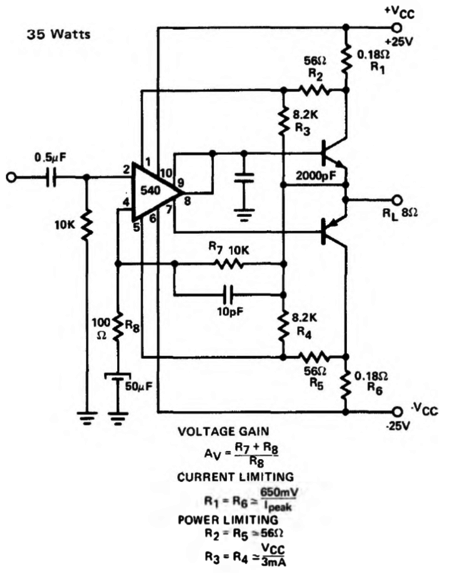
On the other hand, if each parallel transistor gets its own emitter resistor, current hogging ends, as the emitter resistor imposes a negative feedback mechanism: the greater the current flow through the emitter resistor, the bigger will be the voltage drop across the resistor, which will work to decrease the transistor's current flow. (Lateral MOSFETs exhibit a negative-temperature characteristic, wherein the hotter the MOSFET becomes, the less current it draws. Unfortunately, the temperature at which the MOSFET starts to decrease its conduction is often too high to be of use in typical power amplifiers.) The question is how can we design a transistor-based output stage that forgoes emitter resistors? One path to follow is not to use parallel output transistors. Another path to follow, paradoxically enough, is to run the output stage in either class-B or class-A, but not class-AB. By class-B operation, I mean near zero conduction of the output transistors at idle. Many early solid-state amplifiers held such an output stage, which also held no emitter resistors. Here is an example from the Signetics' NE540/SE540 datasheet.
The two output transistors share a bias voltage of only 0.7V, which is insufficient to keep both transistors turned on at idle. At extreme output, when the output transistors approach melt down, their base-to-emitter voltage might fall low enough to turn on both at the same time, but the SE540's internal current-limiting circuit will kick in to shut down the output stage, which explains what resistors R1 through R6 are doing.
At the other extreme of current conduction, we have class-A amplifiers. We all know that a class-A amplifier will be huge, heavy, and expensive—but it can be easier to design. Why? The required high idle current and the average of the peak output current are identical, which makes auto-biasing circuits easier to design and implement.
Let's start with a simple example: a single-ended, unity-gain, power buffer for driving low-impedance headphones.
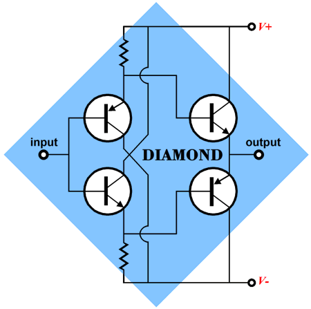
Only two transistors are used. Transistor Q1 is a simple emitter follower that presents a high input impedance and a low output impedance, which is needed to drive transistor's base. This power buffer is actually a form of the famous diamond configuration, which usually uses four transistors.
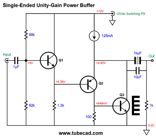
If we build this circuit, we will find that it certainly works, but we can go further, as the following schematic reveals.
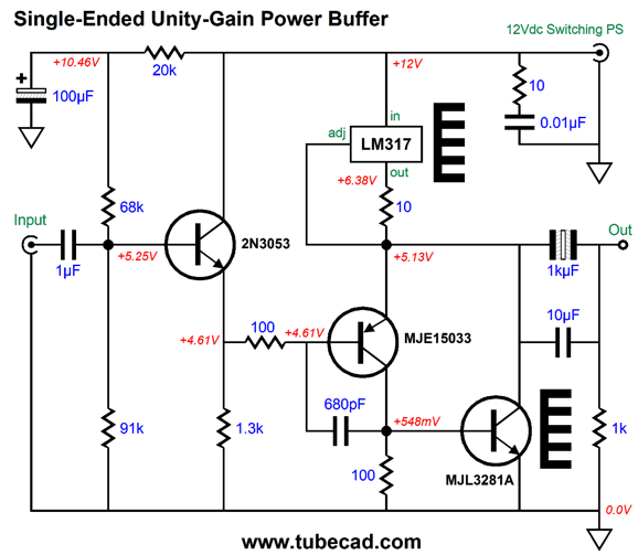
We added an extra NPN transistor (Q3), which creates the compound output stage made up of transistors Q2 and Q3. Transistor Q2 controls (enslaves) transistor Q3, with Q3 drawing the heavy current, which in turn explains why it gets a heatsink, not Q2. Once again, no emitter resistors are used in the output stage. What auto-biases the output stage is the constant-current source. Even if transistors Q2 and Q3 are cold or hot, the constant-current source forces an idle current flow of 125mA. We can roughly deduce the current flow through transistor Q2 by measuring the voltage drop across its collector resistor: 0.548V/100 ohms equals 5.5mA. Well, I did say roughly, as 5.5mA is the very limit to how little current it conducts, as transistor Q3's base also draws some current. How much? In SPICE simulations, 0.88mA flows through the base. We do the math and find that Q3 draws 119.3mA. The constant-current source also sets a limit to the output power and voltage swing. For example, with a 32-ohm headphone driver, the maximum peak voltage swing would be 4Vpk, as 0.125A against 32-ohms equals 4Vpk. If we limit the output to 3.2Vpk, the THD falls appreciably and the array of harmonics defines a lovely single-ended cascade. With 3.2Vpk, the 32-ohm headphone will develop 160mW of power, as 3.2² divided by 2 x 32 equals 0.16W. Plenty, for most headphones, as smart phones and iPods put out about 1Vpk (16mW). How do we make a 125mA constant-current source? The easiest solution is to use an LM317.
Yes, I did sneak in a lot more. The LM317 strives to establish a fixed 1.25V voltage differential between its output pin and its adjustment pin. Divide 1.25 by the current-setting resistor (10-ohms in this example) and you get the idle current flow 0f 125mA.
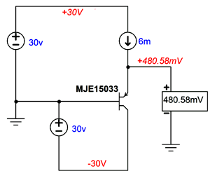
Since the LM317 must lose at least 1.25V (in addition to its own required voltage overhead), we do not center the output stage's center output voltage at 6V, but 5.15Vdc, which makes for the largest symmetrical potential output voltage swings with a 50-ohm load impedance. The MJE15033 PNP transistor might seem a bit of over-specification, as it draws so little current. True enough, but I like not having to worry about having to provide it a heatsink. Moreover, I fear temperature-shift-induced distortion, which the larger transistor's inner die's greater mass can resist better than a tiny TO-92 transistor's die can. The compound output stage is a two-transistor negative feedback circuit in itself. In this circuit, the MJE15033 is in charge, as it sees the output at its emitter and compares it to the signal at its base and then makes corrections as needed. As all electronic devices are bandwidth limited at some high frequency, phase discrepancies can lead to oscillation or peaking at some high frequency. The 680pF capacitor and the 100-ohm resistor impose high-frequency rolloff below the problem frequency. The 10-ohm resistor and 0.01µF ceramic capacitor convert some of the high-frequency hash from the switching power supply into heat through the resistor. The 20k resistor and 100µF capacitor defines an RC low-pass filter to prevent any of the power-supply noise from leaking into the input. Before moving on to a push-pull design, we should go over how the constant-current source forces the output stage to draw the desired current. We start with transistor Q2. Its base voltage is fixed at 4.61Vdc. Its emitter voltage depends on the constant-current source, as the constant-current source adjusts Q2's emitter voltage until the constant-current source experiences is target current flow. Since transistors exhibit such staggeringly huge transconductances, a tiny change in the base-to-emitter voltage results in a huge change in current flow. For example, if we spray liquid nitrogen onto the transistor Q2, it will dramatically cool and its base-to-emitter voltage will increase, to which the constant-current source will instantly accommodate. On the other hand, if we blow a hair-drier's heater air at it, its base-to-emitter voltage will decrease. Here is a graph that shows how the PNP MJE15033 transistor's base-to-emitter voltage changes with temperature.
The voltage decrements are in millivolts; the temperature is in Celsius. The SPICE circuit was easy enough to create:
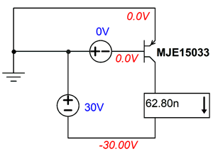
(Strictly speaking, in SPICE the +30V voltage source is not needed, but conceptually it is.) The next graph helps us see how a small change in a transistor's base-to-emitter voltage results in a huge change in current conduction.
The SPICE circuit is equally simple to the previous one.
Note that a messily 0.1V change in base-to-emitter voltage, from -0.7V to -0.8V results in a 2.8A increase in current conduction. In contrast, the 300B, with a cathode-to-plate voltage of 300V, experiences about 1mA increase in conduction when its grid is raised from -0.8V to -0.7V. Do not forget that 2.8A equals 2,800mA. Thus, the MJE15033 PNP transistor is 2,800 times more sensitive to a change in its base-to-emitter voltage than the 300B is to a change in its grid-to-cathode voltage.
This helps explain why we must make big twist in a tube-based amplifier's bias potentiometer, but a micro twist of a solid-state power amplifier's bias potentiometer is enough to blow a fuse. Okay, now imagine two output transistors in a push-pull arrangement, with no emitter resistors. How can we auto-bias the transistors and prevent the transistors from overheating?
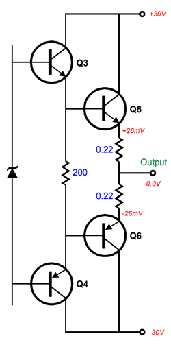
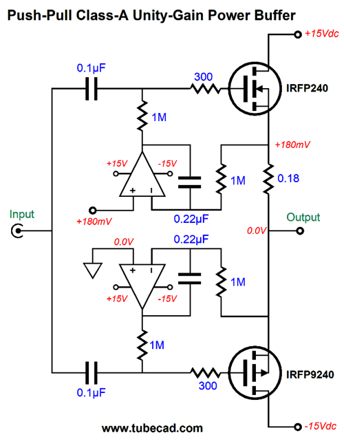
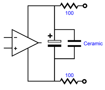
Push-pull Class-A Power Buffer If the solid-state output stage uses emitter resistors, we can use the voltage drop across the resistors to monitor the current flow through the output stage. In the absence of emitter resistors, we must find a different way to monitor the idle current. Here is a simple push-pull, class-A power buffer that uses two MOSFETs and two OpAmps.
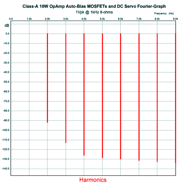
The top OpAmp sets and maintains the idle current through the MOSFETs. It is able to perform this task because the output stage runs in class-A. If the output stage ran a leaner idle current, its 0.22µF capacitor would see greater positive voltage swings than negative swings, which would excessively charge up the capacitor, which in turn would prompt the OpAmp to reduce the top MOSFET's gate DC bias voltage, possibly to the point of turning off output stage altogether. Not good. The bottom OpAmp is configured as a DC servo that eliminates DC offset voltages from the output. In addition, it ensures that that at idle both top and bottom MOSFETs draw and equal amount of current. (The only way a DC offset can be eliminated is if both output MOSFETs draw the same current.) Why didn't the bottom P-MOSFET get a 0.1-ohm source resistor? The N-MOSFET above offer slightly greater transconductance, so its source resistor reduces its transconductance to better match the bottom MOSFET. By the way, the ratio of roughly 1:2 between the input coupling capacitors and the DC servo 0.22µF capacitors must be maintained to ensure a smooth, bump-free rolloff at low frequencies. The design goal was a 10W class-A power buffer, which implies a peak voltage output swing of 12.65Vpk and 1.58Apk into 8-ohms. The 1A of idle current implies a peak output current swing of 2A, which is quite a bit more than the 1.58A needed for 10W of output into 8 ohms. The thing is that few loudspeakers actually present a fixed 8-ohm load. For example, some highly esteemed loudspeakers produce impedance plots that dip down to 2 ohms, due to poor crossover design. In addition, if a 4-ohm speaker were attached to this power buffer, the peak swing of output current of 2A would result in a peak voltage swing of 8V and 8W of power delivery. Had we chosen an idle current flow of just 0.8A, the peak swing of output voltage would be 6.4V and 5.12W. In other words, it's a sound practice to over design. Here is the SPICE-generated Fourier graph for 1Vpk at 1kHz into an 8-ohm load.
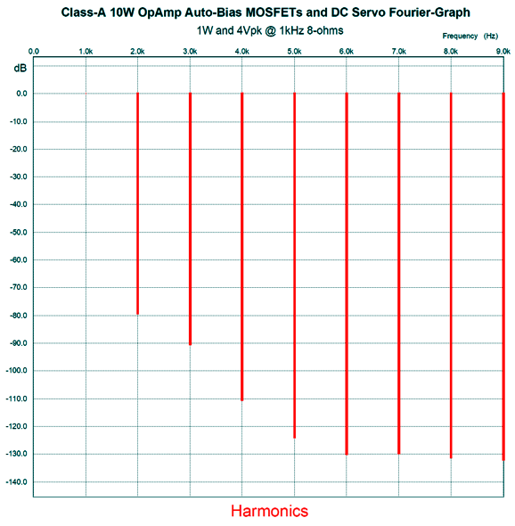
The THD is below 0.01% and the cascade of harmonics is sweetly single-ended. At 1W of output, 4Vpk, the distortion increases only slightly.
At full output, 10W, the THD rises only a tad (0.0114%), which isn't at all bad for a negative-feedback-free design. One nice feature of this design is that the OpAmps can run directly off the bipolar power supply, however, I would decouple them from the power supply by using RC filters with 100-ohm resistors.
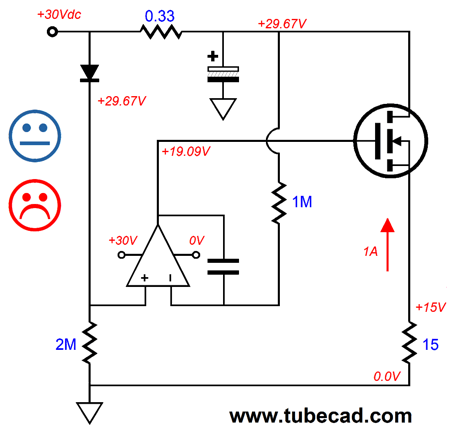
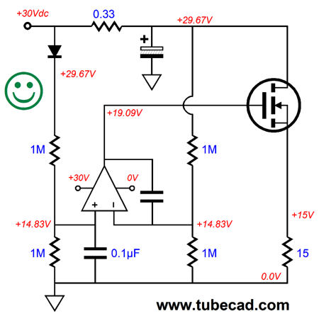
Since this is a unity-gain power buffer, the line-stage amplifier must supply the needed signal gain. A 6DJ8-based Aikido amplifier would easily provide the missing signal gain. The output stage dissipation is 30W at idle, so each most must dissipate 15W, which implies a largish heatsink. Okay, how do we eliminate the source resistor and still auto-bias the output MOSFETs? In addition, how do we use a monopolar power supply instead of the bipolar power supply? The first step is to specify a 30Vdc B+ voltage. The next step is to find a way to monitor the idle current flow without using source resistors, which leaves us with collector resistors. We only need one, and it can be placed in series with either the top or bottom MOSFET's collector. Let's start with the top.
The MUR420G rectifier serves as a voltage reference in this circuit. The 0.33-ohm current-sense resistor also forms an RC filter with the electrolytic capacitor, which will scrub away the high-frequency hash from the switching power supply. The OpAmp compares the voltage drop across the rectifier to the drop across the current-sense resistor, and it strives to maintain equal voltage at both its inputs. The 15-ohm load resistor reveals the 1A idle current flow through the MOSFET. The problem with this approach is that few OpAmps like to see their inputs that close to their positive-power-supply pin's voltage. In addition, the OpAmp will pass along al the power-supply noise at its output. Moreover, at startup up, the OpAmp's positive input will see almost 30V, while its negative input will something closer to ground potential, as the capacitors have yet to charge up; this situation might force the OpAmp into a latch-up mode, wherein its voltage latches to B+ voltage and stays stuck. Here is the workaround.
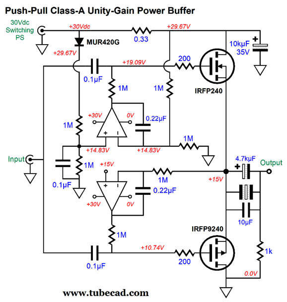
The four 1M resistors form two two-resistor voltage dividers, so the OpAmp's inputs are at close to half the B+ voltage. The added 0.1µF capacitor on the positive input and the RC filter work to create a slow ramp up of voltage across the 15-ohm resistor. Okay, let incorporate this circuit within the power buffer.
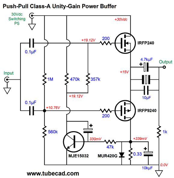
The bottom OpAmp simple centers the MOSFETs to half the B+ voltage, while the top OpAmp sets the idle current flow. No source resistors were used. We must use a high-capacitance output coupling capacitor to drive 8-ohm loudspeakers, which explains the 4.7kµF capacitor value, which ensured low-frequency bandwidth down to 5Hz. This capacitor is then bypassed by a non-polarized electrolytic and a film capacitor. If we wished to place the current-sense resistor in series with the P-MOSFET's collector, we would just stand the auto-bias circuit on its head. Let's say that you don't like OpAmps, preferring discrete solid-state devices. No problem. Here is a variation that uses a single NPN transistor in place of the OpAmp.
Note that only the top MOSFET's gate voltage is adjusted, as the bottom MOSFET's gate is set to a fixed Dc voltage due to the two-resistor voltage divider made up of the 1M and 560k resistors. The MJE15032 NPN transistor monitors the voltage drop across the current-sense resistor, which is shunted by a large-valued capacitor and a rectifier. The MUR420G rectifier limits the voltage drop to no more than about 6.2Vdc. The reason the NPN transistor's base-to-emitter voltage is so low is that the transistor is drawing so little current. This transistor exhibits positive temperature response, where its base-to-emitter voltage decreases as the device gets hotter. In other words, if the transistor gets too hot, the idle current will fall. Here is a SPICE-generated graph that shows the relationship.
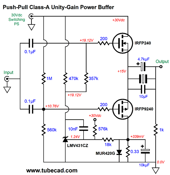
As we can see, at 32°C (89.6°F), the idle current flow is 1A. A reasonable expectation is that the inside of a class-A amplifier (or power buffer) will be toasty warm, if not hot. A workaround is to replace the NPN transistor with a shunt voltage reference, such as the LMV431CZ, which has been optimized for temperature stability. Much like other shunt voltage references, such as the TL431 and LM431, the LMV431CZ is three-pin shunt regulator with an NPN transistor pass device, an OpAmp, and voltage reference. Unlike the TL431 and LM431, the LMV431CZ's internal voltage reference is set to 1.24V, not 2.5V. Now, we do not want to throw away 1.24V of our 30V B+ voltage, so we need to add a resistor that terminates into the B+ voltage to bring the two-resistor voltage divider's output voltage up to 1.24V.
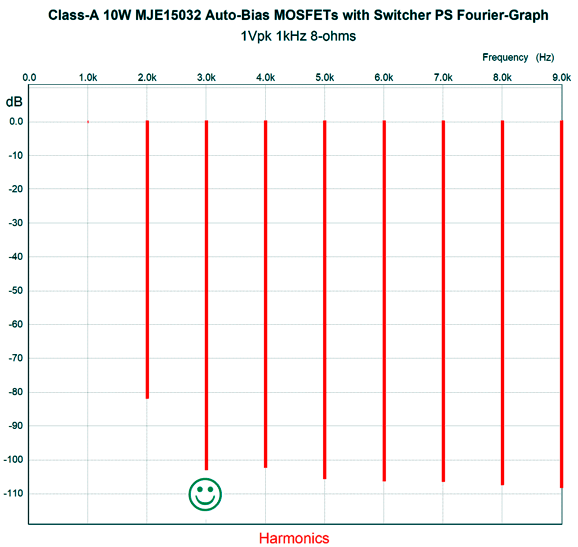
Since switching power supplies offer fairly good voltage regulation, this setup works well. In fact, it also works well with a conventional power supply filled with huge capacitors and a massive power transformer, as the result is a constant-power dissipation resulting from the 576k and 18k two-resistor voltage divider terminating into the B+ voltage. In other words, the idle current flow decreases with increased B+ voltage, but increases with decreased B+ voltage. (See post 347 to see many design examples of constant-power dissipation.) How well does this simple power buffer perform? Here is the SPICE-generated Fourier graph for 1Vpk of output with the MJE15032 auto-bias circuit.
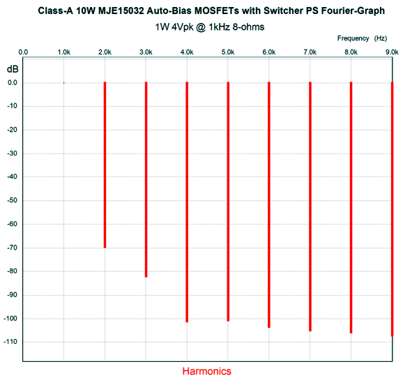
Note the 3rd harmonic's reduction. Next, we see 1W (4Vpk) into 8 ohms.
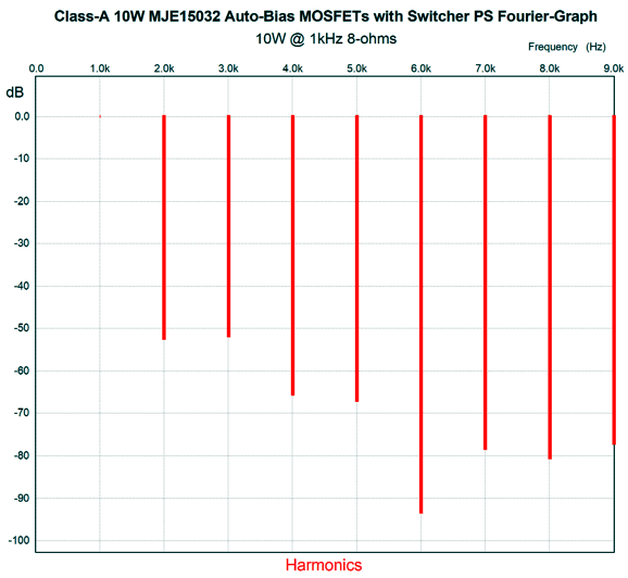
Quite nice. Finally, we see full output, 10W.
A tad jagged, but quite serviceable. One problem I spotted was that the N-channel IRFP240 MOSFET offers greater transconductance than its P-MOSFET partner, 6.9A/V versus 4.2A/V. The 1.64:1 ratio cause an imbalance in current swings, which screws up the class-A operation, as the N-channel MOSFET will do more work than the P-channel MOSFET. The workaround is to give the N-channel MOSFET a source resistor. How big a resistor? The formula for the effective transconductance of MOSFET with a source resistor is: gm' = gm / (1 + gm·Rs), where Rs is the source resistor. Thus, if Rs equals the inverse of the MOSFET's transconductance, then the effective transconductance will be halved. We rearrange the formula to solve for Rs: Rs = (gm – gm')/gm'² We plug in the variable values and get an Rs of 0.153 ohms, with 0.15 ohms being close enough. By the way, we can see an additional advantage to using cathode, emitter, and source resistors. Had both MOSFET been given a 0.22-ohm source resistor, as the resulting 1.26:1 ratio is much closer to 1:1 than is the 1.64:1 ratio. Okay, let's move on to bipolar power transistors. The OpAmp-based auto-bias circuits work far less with transistors, as the base draws current, unlike the MOSFET's gate. In other words, a high-resistance resistor and a small-valued coupling capacitor won't cut it.
Unity-Gain Push-Pull Headphone Power Buffer The best way to drive a pair of symmetrical output transistors is with a symmetrical emitter follower.
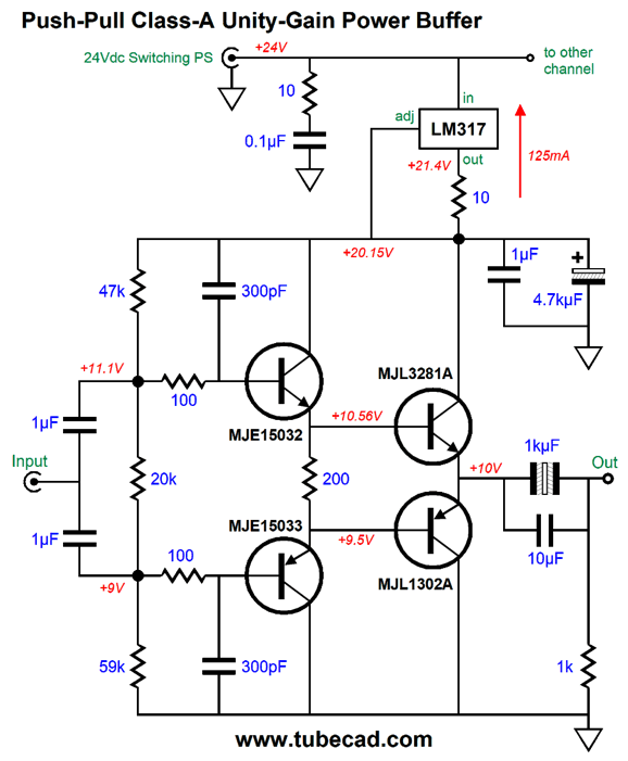
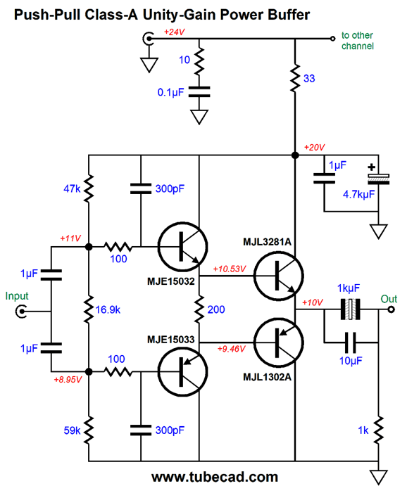
The MJE15032 and MJE15033 driver-stage pairing is famous in solid-state power amplifiers. The transistors were developed for fairly high-voltage use and are robust. The MJL3281A and MJL1302A output pairing are also in wide use. They cost more than other output transistors, but they are worth it, as they offer better performance and come in the large TO-264-3 package. To make this output stage auto-biased will be tricky, as the transistors are extremely sensitive to small variations in base-to-emitter voltage. How about using a constant-current source to set the idle current?
The LM317 is configured as a 125mA constant-current source. Each channel gets its own LM317 and 4.7kµF decoupling capacitor. The string of resistors, 47k and 20k and 59k, form a two-output voltage divider, with 2.11V of differential voltage between outputs. If the output stage draws less than 125mA at idle, the constant-current source will pull up the B+ voltage until the voltage divider delivers enough voltage to force the 125mA idle current flow. Conversely, if the idle current climbs too high, say due to the output transistors heating up excessively, the constant-current source will drop the B+ voltage to bring the 125mA current flow into being. The 10-ohm resistor and 0.1µF capacitor are there to turn the high-frequency switcher hash into heat. In addition, the constant-current source and 4.7kµF decoupling capacitor form an extreme RC filter that provides clean B+ voltage. Remember, headphone use requires the best PSRR possible. The 100-ohm resistors and 300pF capacitors also form low-pass RC filters, which limits the high-frequency bandwidth, so the output transistors do not get into trouble, such as oscillation at extreme high frequencies. Since this power buffer offers no signal gain, we must get it from elsewhere, such as a high-output DAC or a tube-based line-stage amplifier. The 125mA idle current sets a maximum output current swing of 250mA peak, which against a 32-ohm headphone driver equals an 8Vpk output voltage swing and 1W of output power, which is huge, as headphone amplifiers are rated in milliwatts, not watts of output. The THD at 1W at 10kHz into 32-ohms in SPICE simulations was below 0.1%; with 1Vpk of output, the THD falls below 0.01%. The output impedance is a fraction of an ohm (about 0.13 ohms). The -3dB bandwidth extends from 4Hz to 850kHz, assuming a signal source impedance of 200 ohms. The PSRR is crazy good.
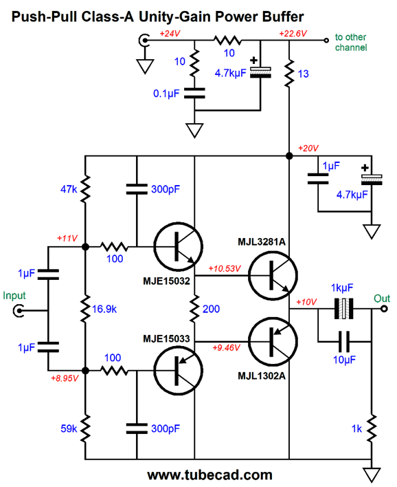
Usually, we look at 100Hz and 120Hz; not this time. Switching power supplies produce a ripple frequency between 30kHz to 100kHz, with most centering at about 48kHz. By the way, we can replace the LM317-based constant-current source with a 33-ohm power resistor.
The PSRR, while still stellar, is not as good as it was with the constant-current source. The workaround is to add another RC filter.
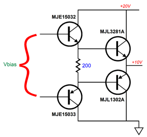
Now, the PSRR is better than with the LM317-based constant-current source. Of course, we could add an RC pre-filter to the LM317-based constant-current source, say 1-ohm and 1kµF, but I would fear tripping up the switching power supply's built-in current-limiting circuitry due to the peak current inrush to charge the large-valued capacitors. In contrast, the constant-current source produces a linear ramping up of voltage across the 4.7kµF capacitor. Okay, I know that some are wondering if a beefier version could be built to drive loudspeakers, say one that used a 48Vdc switching power supply. It could, but we would have to multiple output devices in parallel and emitter resistors. Doubling the B+ voltage in a class-A amplifier quadruples the heat dissipation. One problem with this constant-current loading of a transistor output stage, especially one without emitter resistors, is that Vbias voltage is relatively small compared to the B+ voltage.
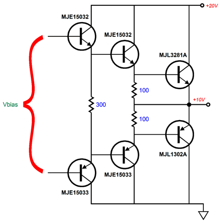
In contrast, a MOSFET-based output stage presents a much larger Vbias voltage. One workaround is to use Darlington driver transistors.
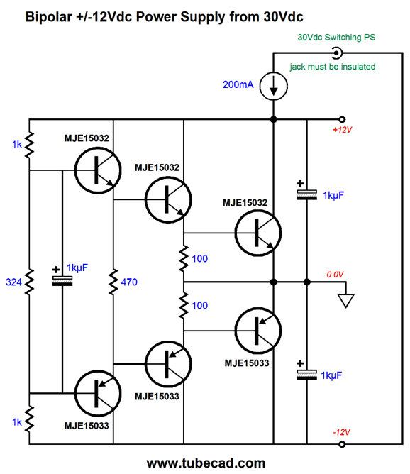
We have increased the Vbias voltage by the two added base-to-emitter voltage drops. Why is this important? We want the constant-current source to drop as little of the B+ voltage as possible, say no more than 3V to 4V. Fortunately, switching power supplies offer fairly good voltage regulation, usually about 3%. (Line regulation is different and often as low as 1%.) Since we can be sure that the target B+ voltage will actually be delivered to the circuit, something a regular big-transformer conventional power supply cannot do, the CCS solution to auto-bias makes sense. Here is an odd application that forgoes emitter resistors: a rail-splitter circuit.
The constant-current source (CCS) sets a strict current limit of 200mA, which is plenty for most OpAmp-based audio projects. In addition, the CCS insulates the circuit from the switcher ripple. The two 1kµF capacitors in series provide a low output impedance at high frequencies. The transistors extend the low output impedance down to DC. As I look over the schematic, I see that I should have specified 10kµF capacitors on the outputs. Note that the ground is not the DC power jack's negative terminal. In other words, the DC power jack must be fully insulated from the chassis. How do we make a 200mA constant-current source? Once again, the easiest solution is to use an LM317.
Music Recommendation: Your Music, But in Hi-Res What instantly struck me were not extra sparkling highs, but a more relaxed sonic presentation. This was not a first-time experience, as most high-resolution recordings sound more analog to my ears. Amazingly, the deeper the bit depth and the higher the sampling rate, the more the sonics resemble good open-reel-tape playback. You should give this a try. Just find some beloved album on your hard-drive and then hunt for a higher-res version on Tidal or Amazon Music. Perform a quick AB test. Perhaps, you will experience the same thing I did: music I loved hearing from a car radio, then from an LP, but not from a CD, but later did love from a high-res digital file. Of course, there are great sounding 16-bit CDs, with some sounding amazingly fine, so bit depth and sampling rate do not explain all. No doubt, part of the problem with some CDs was a lazy or rushed transfer from the analog master tapes to the CD. Thus, I am sure it would be worth performing a shootout of the CD and the streaming service's 16-bit stream, as the latter might have gotten a more careful transfer into a digital file.
//JRB
Did you enjoy my post? Do you want to see me make it to post 1,000? If so, think about supporting me at Patreon.
User Guides for GlassWare Software
For those of you who still have old computers running Windows XP (32-bit) or any other Windows 32-bit OS, I have setup the download availability of my old old standards: Tube CAD, SE Amp CAD, and Audio Gadgets. The downloads are at the GlassWare-Yahoo store and the price is only $9.95 for each program. http://glass-ware.stores.yahoo.net/adsoffromgla.html So many have asked that I had to do it. WARNING: THESE THREE PROGRAMS WILL NOT RUN UNDER VISTA 64-Bit or WINDOWS 7, 8, and 10 if the OS is not 32-bit or if it is a 64-bit OS. I do plan on remaking all of these programs into 64-bit versions, but it will be a huge ordeal, as programming requires vast chunks of noise-free time, something very rare with children running about. Ideally, I would love to come out with versions that run on iPads and Android-OS tablets.
|
I know that some readers wish to avoid Patreon, so here is a PayPal button instead. Thanks. John Broskie
John Gives
Special Thanks to the Special 82 To all my patrons, all 82 of them, thank you all again. I want to especially thank
All of your support makes a big difference. I would love to arrive at the point where creating my posts was my top priority of the day, not something that I have to steal time from other obligations to do. The more support I get, the higher up these posts move up in deserving attention.
If you have been reading my posts, you know that my lifetime goal is reaching post number one thousand. I have 447 more to go. My second goal was to gather 1,000 patrons. Well, that no longer seems possible to me, so I will shoot for a mighty 100 instead. Thus, I have just 18 patrons to go. Help me get there. Thanks.
Support the Tube CAD Journal & get an extremely powerful push-pull tube-amplifier simulator for TCJ Push-Pull Calculator
TCJ PPC Version 2 Improvements Rebuilt simulation engine *User definable
Download or CD ROM For more information, please visit our Web site : To purchase, please visit our Yahoo Store: |
|||


| www.tubecad.com Copyright © 1999-2022 GlassWare All Rights Reserved |