| John Broskie's Guide to Tube Circuit Analysis & Design |
15 October 2022 Post Number 568
More Loudspeaker-Internal Amplifiers
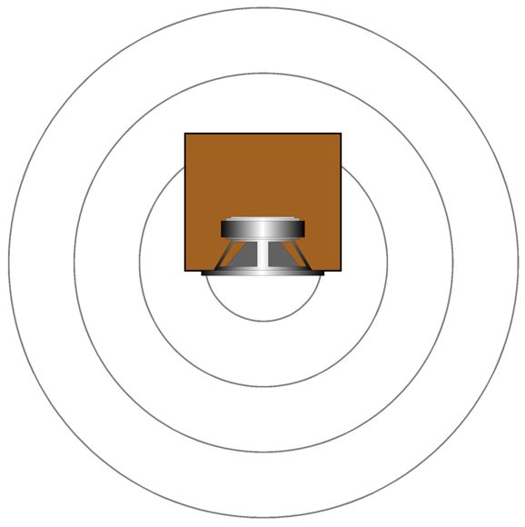
This necessary limitation to only solid-state power amplification leads to my pondering about a compromise of sorts: using an internal solid-state power amplifier to drive just a built-in subwoofer, so the tube-based power amplifier can be external to the loudspeaker. Sadly for me, this idea leads to big enclosures, which in turn requires table and radial-arm saws that I do not own. Thus, after seeing so many wonderful potential ideas die, I was left with only small loudspeakers. For example, one possibly doable small loudspeaker would be one with active diffraction-loss compensation, wherein an internal power amplifier drives an identical smallish woofer on the back of the speaker enclosure. The internal power amplifier and back-firing woofer only cover the same audio bandwidth as the front-firing woofer, which must be truncated, as we only want to fill-in the deep bass lost to diffraction. In other words, bandwidth no higher than about 300Hz to 400Hz. Where to start?
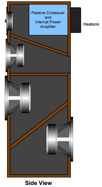
Imagine a small three-way loudspeaker with a 6-inch woofer, four-inch midrange, and a 1-inch dome tweeter.
The crossover frequencies are 300Hz and 3kHz. The 300Hz crossover isn't as arbitrary as it may seem. For any given loudspeaker cabinet width and depth, there is an optimal corresponding crossover frequency with diffraction-loss compensation. For example, if the speaker enclosure is so small that the bass loss starts at 500Hz, then 500Hz should be the crossover frequency. On the other hand, if the enclosure is much larger, so the roll-off occurs at 200Hz, then 200Hz is the desired crossover frequency. The crossover filter alignment might be 1st-order or, possibly, 2nd-order, and probably never 3rd-order. My guess is that a low-pass 1st-order would prove best, as the loudspeaker's diffraction-loss roll-off mimics the 1st-order slope.
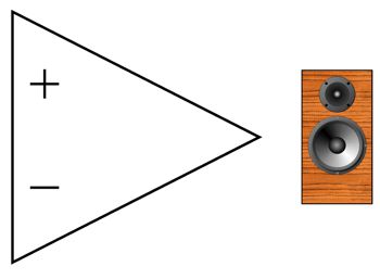
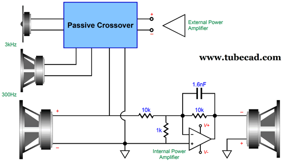
The external power amplifier (preferably tube-based) drives all three front drivers, while a passive crossover separates the bands of signals for each front driver. The rear woofer is driven only by the internal power amplifier; the internal amplifier's input signal is the signal delivered to the front-firing woofer's terminals after having passed through the crossover's low-pass filter and an attenuator.
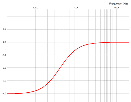
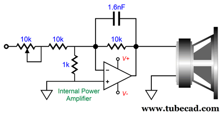
The 10k attenuator is needed to adjust the rear-firing woofer's output. At one extreme, the attenuation is -6dB; at the other, unity-gain. Why? If you listen to the loudspeaker in an anechoic room, the rear-firing woofer needs to put the same SPL as the front-firing woofer, as in this acoustic environment, the front-firing woofer will undergo a 6-dB deep bass loss due to the speaker going from hemispherical radiation to omnidirectional radiation at some low frequency. But with the loudspeaker sitting atop short speaker stands and located two feet from the rear wall, the deep-bass loss might only be -2dB, so very little bass reinforcement would be needed. A simple volume potentiometer would allow fine-tuning of the diffraction-loss adjustment.
The internal power amplifier is configured in the inverting arrangement, which explains why the rear-firing woofer's phase is inverted. The 1.6nF capacitor imposes a 1st-order low-pass filter at 10kHz. The odd component is the 1k resistor. Why is it there? The assumption here is that common chip power amplifiers, such as the LM1875 or LM3886 will be used. These chip amplifiers are not unity-gain stable. The inclusion of the 1k resistor effectively increases the internal power amplifier's gain to 1:10 (20dB), while also decreasing the input signal by 1/10, which results in unity-gain at the output, albeit inverted. In short, we are throwing away negative feedback to achieve unity-gain stability. The Bur-Brown chip amplifiers, in contrast, are unity-gain stable, so the 1k resistor is not needed. The next design decision is how much power should the internal power amplifier put out? My main power amplifiers are tube-based single-ended types that put out about 13Vpk, which translates into about 10W. Thus, the internal power amplifier need only be able to deliver 13W, which is so wimpy an amount that the LM1875 chip amplifier and an external switching power supply of 36Vdc @ 2A would probably suffice. But what if a more powerful amplifier were used, say one with 30W of output? Well, the LM3875 or LM3886 and 56Vdc power supply would be needed. What if a 100W or 200W external power amplifier were used? Well we run into problems.
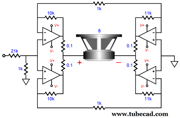
To deliver 100W into an 8-ohm load impedance, we need 40Vpk and 5Apk; for 200W, 56.6Vpk and 7.07Apk. That's a lot of peak voltage and current swing. If the internal amplifiers were setup in a parallel-balanced (bridge) configuration, we could probably get 144W from four big chip power amplifiers, such as the LM886.
Since the rear-firing woofer might be down -3dB relative to the front-firing woofer, only 100W would be needed from the internal power amplifiers to match the 200W external amplifier, as -3dB implies only 70.7% of the 56.6Vpk voltage swing, equaling 40Vpk, which equals 100W into 8 ohms.
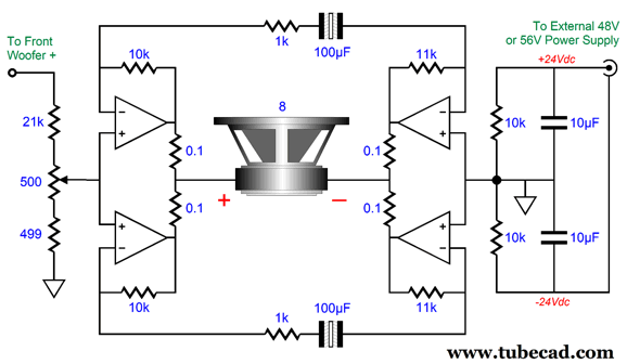
The 21k and 1K input resistors define a two-resistor voltage divider that delivers 1/22 of the voltage swing that the front woofers sees. Each amplifier yields a gain of 1:11, which becomes doubled across the woofer; Thus, the bridge amplifiers total gain is 1:22, which undoes the attenuation, bringing us to unity gain. As far as each chip amplifier is concerned, it is driving an 8-ohm load. So if 100W is delivered into the woofer, each amplifier must put out 25W. Lots of parts are missing from the schematic, such as Zobel networks and negative feedback-loop capacitors, but you get the concept: the two sides of amplifiers deliver equal, but inverting output voltage swings, so the woofer sees twice the voltage swing that each amplifier is putting out, so 20Vpk become 40Vpk. A monopolar 48Vdc or 56Vdc power supply is all that is needed. What? Why not use a bipolar power supply instead?
We could, but most desk-top switching power supplies are monopolar. Since the rear-firing woofer does not terminate into ground, however, but another amplifier output, we can get away with a monopolar power supply.
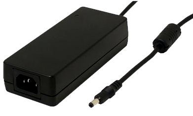
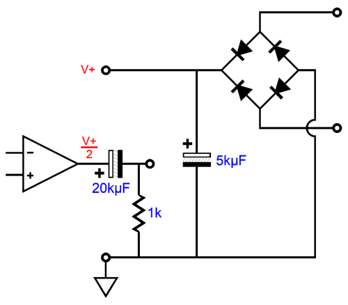
The added 100µF nonpolarized capacitors prevent any DC offset on the front-firing woofer from being amplified. The two 10k resistors form a voltage divider that splits the power supply voltage and creates a faux center-tapped ground. The two 10µF film capacitors may seem inadequate, but the external switching power supply offers a regulated output voltage; in addition, the power supply would run into output-current-overload protection with a typical high-value power-supply reservoir capacitor of 10kµF. In other words, too large a capacitor value and the external switching power supply will choke on the initial current inrush, which can be huge, as switching power supplies instantly ramp up to full output voltage. Workarounds exist, but they are a pain.
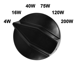
What if we forgo the switching power supply and use an internal conventional toroid power transformer and big capacitor power supply? (We could conceal it into a metal speaker stand.) This idea instantly spawned many new ideas. For example, what if we added a rotary switch that would allow us to specifiy the power-supply DC voltage?
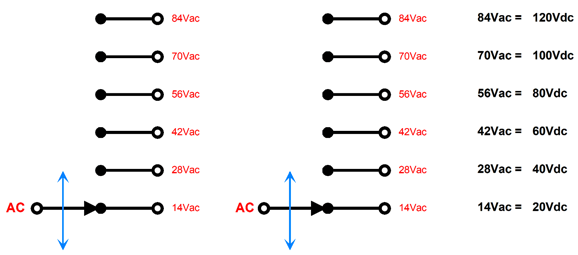
The six switch positions are labeled in watts, but they could be labeled in DC voltages instead. The rotary switch must offer two poles and six positions.
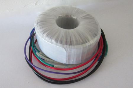
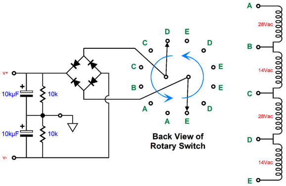
As we rotate the knob clockwise, the two switch contacts move in unison, climbing up in AC voltage that the conventional power supply will transform into DC. Thus, the loudspeaker with the powered rear-firing woofer could be used with flea-power amplifiers and huge beasts of amplifiers. Wouldn't having to have a custom-made power transformer prove both difficult and super expensive? A multi-tap power transformer would cost a bundle of cash, but we could use two off-the-shelf power toroid transformers instead.
The transformer with two 28Vac secondaries could be rated for 300VA, while the other transformer need only be rated for 150VA. We wire all the secondaries up in series, while all the primaries are wired up in parallel (well, at least they would be here in North America; series-parallel in Europe and elsewhere).
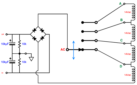
The rotary switch feeds the rectifier circuit its AC input voltage. If you follow each switch position, you see that the AC voltage climbs by 14Vac with each step. Here is how we would wire up the back of the switch.
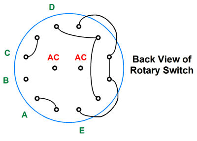
Just five hook-up wires are needed. By the way, the assumption with this arrangement is that a regular non-bridge internal power amplifier would be used. The faux grounded created by the two 10k resistors cannot pass much DC, whereas a true ground from a center-tapped secondary can. In other words, the internal amplifier is effectively capacitor-coupled at its output. We could use the following setup instead, which would deliver the same performance.
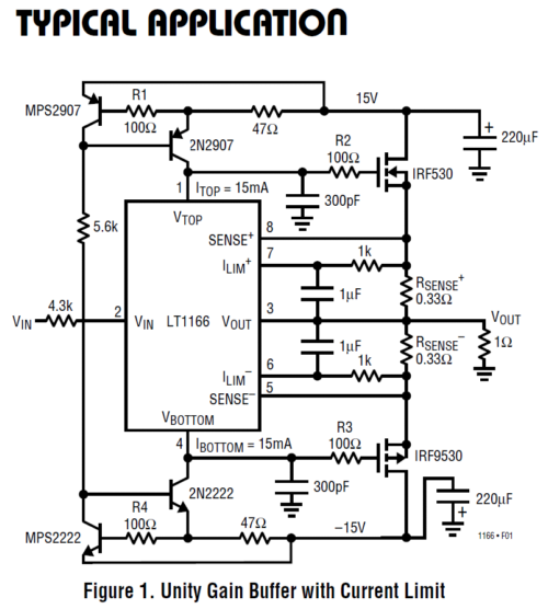
In the original set with the stacked 10kµF capacitors, the power supply saw 5kµF of capacitance, as the two 10µF capacitors are in series, which halves their value ; in contrast, the woofer saw 20kµF of capacitance, as the two 10µF capacitors are effectively in parallel from the speakers point of view. Which is better? I would say that it is a tie. One advantage to the capacitor-coupled output is that we cannot ignore the capacitor. The bridge amplifier does not need any output capacitors, as both outputs are at the same voltage potential. Indeed, if we forgo the bridge amplifier, it need not be an amplifier but only a unity-gain power buffer. For example, the LT1166 auto-bias and MOSFET driver stage IC that we saw in posts 211 and 554 could be used, but with much higher rail voltages.
On the other hand, since a bridge amplifier configuration is planned and since most tube-based amplifiers do not put out a lot of power, we could use two lower-voltage power transformers, both with two 14Vac secondaries, as all four in series would yield 56Vac, which would rectify up to 80Vdc. (No, I am not forgetting rectifier voltage drops. My assumption is that the transformer's primary expects to encounter 115Vac, whereas my wall voltage is closer to 120Vac; in addition, they would be rated 14Vac under load, which we won't approach at idle.) A bridge amplifier with an 80Vdc monopolar power supply could easily put out 200W into an 8-ohm load impedance. The change to all 14Vac secondaries means that we can only chose from four DC voltage increments, not six. Thus, a one-pole, four-position rotary switch is needed.
In reality, one-pole, four-position rotary switches are hard to find, but three-pole, four-position rotary switches are not. We can wire up the three sets of one-pole four-position rotary contacts in parallel, which would triple the switch's current rating, which is helpful, as a bridge amplifier draws twice the current.
Of course, many would argue that I am over-thinking the problem, as ultra-cheap class-D amplifiers are readily available that could easily deliver 200W without straining. True, they could, but often that much power output only holds true with 4-ohm (or 2-ohm) loads. Let us pause and reflect: the whole point behind my posts is to think anew—to over-think. Part of the process is to strive to overcome the restrictions or workaround those restrictions or, in the best case, embrace the restriction and make it the foundation of a new system. Renouncing the easy-class-D-amplifier solution is both expensive and complicated. The added expense is always regrettable, but the ensuing difficulties, on the other hand, should be welcomed—much in the same way a body builder welcomes the barbell's heavy weights. This selectable power-supply voltage scheme might be just what someone else needed for an entirely different project.
In short, the more tricks you have up your sleeve, the better a magician you will be.
More 300B Power-Doubling Ideas
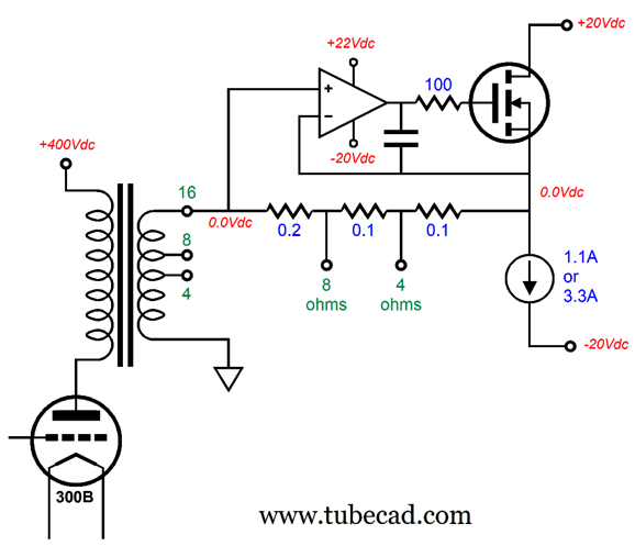
Another possible power-boosting arrangement would be to use a 300B-based single-ended power amplifier with a 16-ohm output tap and single-ended impedance-multiplying circuit that would double the 300B's power output into an 8-ohm load and quadruple it into a 4-ohm load. Let's say the 300B amplifier put out 8W. If we use the 16-ohm output tap output voltage swing (16Vpk) and successfully delivered it to an 8-ohm load, the power would double, as 16Vpk equals 16W into an 8-ohm load impedance. On the other hand, 16Vpk into a 4-ohm loudspeaker equals 32W, four times the 300B's output. The price we must pay is lots of wasted heat dissipation by the single-ended IMC. With an idle current flow of 3.3A and with a bipolar power supply voltages of +/-20Vdc, the IMC must dissipate 132W at idle.
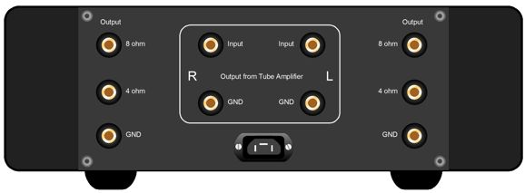
The theoretical maximum efficiency of a constant-current-source-loaded power amplifier is 25%. In this example, the IMC delivers 24W into the 4-ohm speaker (and the 300B amplifier delivers 8W, making a total of 32W), so the IMC's efficiency is only 18%, as 24W/132W equals 0.18. If we retain the IMC idle current flow of 3.3A and drive an 8-ohm loudspeaker, the IMC's efficiency drops to only 6%. The workaround is to select between two idle currents: 1.1A for 8-ohm loudspeakers; 3.3A, for 4-ohm loudspeakers. In this setup, the IMC works like a high-quality solid-state power amplifier, which will deliver twice the wattage into 4-ohms as it did into 8-ohms. The IMC offers two output taps, one for 8-ohm and one for 4-ohms. When a 4-ohm loudspeaker is attached to the 4-ohm output, the IMC ratio is 1-to-4, as (0.2 + 0.1 + 0.1) / 0.1 equals 4. When an 8-ohm loudspeaker is attached to the 8-ohm output, the IMC ratio is 1-to-2, as 0.2 / (0.1 + 0.1) equals 2. Since a picture is easily worth a thousand words, here is what I imagine the back of a stereo power doubler would look like.
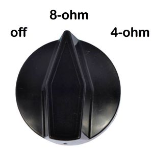
Big heatsinks flank the sides. Two sets of binding posts accept the output from the single-ended power amplifier. Each channel holds three output binding posts. Inside the chassis, a large toroid power transformer and the electronics reside. On the front panel, a rotary power switch would allow setting the IMC's idle current.
The more I think about it, I realize that a better setup might be to use two chassis, one atop the other.
The idea here is that the two chassis are stuck together by four heavy-duty isolation mounts, through which we pass wires. The bottom enclosure holds a large toroid power transformer, power-supply parts, and two high-current constant-current sources. The top enclosure only holds the N-MOSFETs and OpAmps. Just imagine the heft. My back aches from just thinking about it. So far, I have been indulging in a fanciful and extravagant thought experiment. If we were willing to forgo the sonic glory and the bragging rights associated with a class-A, single-ended IMC, we could opt for plain old class-AB amplifiers, which do not get as hot or weigh as much or cost as much as the single-ended constant-current-source-loaded equivalent. In other words, we could get by with a much small enclosure, heatsinks, and power transformer. We would still need 8-ohm and 4-ohm output taps on the IMC. On the other hand, if we used an IMC and an inverting power amplifier to quadruple power output from the 300B (or any other low-power tube-based amplifier), we could forgo the two impedance output posts, as only a positive and a negative would be needed.
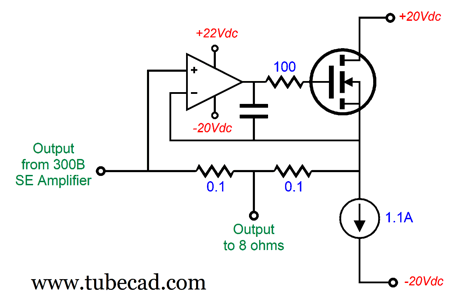
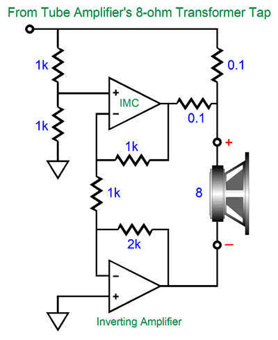
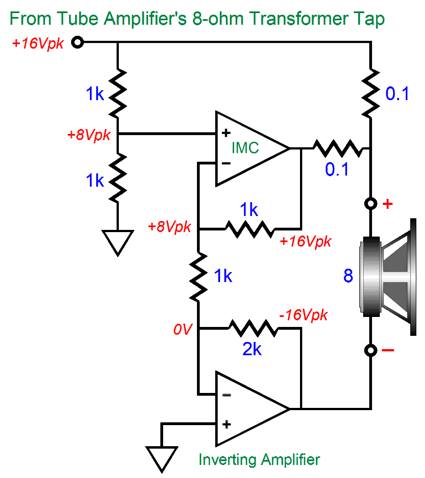
Here we see the basic topology, without all the tweaks, such as Zobel networks and compensation capacitors. The output voltage leaving the tube-based power amplifier is halved by the two 1k resistors. The IMC then amplifies this signal by two, so that its output matches that of the tube-based amplifier. The inverting power amplifier delivers the same output voltage as the IMC, but inverted. The loudspeaker (which includes woofer, midrange, tweeter, and passive crossover) sees twice the voltage that the tube-based amplifier puts out, which increases the power delivered by fourfold. We use the tube-based amplifier's output tap that matches the loudspeaker impedance. The IMC delivers just as much power as does the tube-based power amplifier, while the inverting amplifier must deliver twice as much power. To see why this is so, let's use a peak output voltage swing of 16V from the tube-based amplifier.
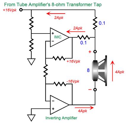
The two-resistor voltage divider halves the 16Vpk to 8Vpk, which the IMC and inverting amplifier restore to +16Vpk and -16Vpk. Now, let's look at the current relationships.
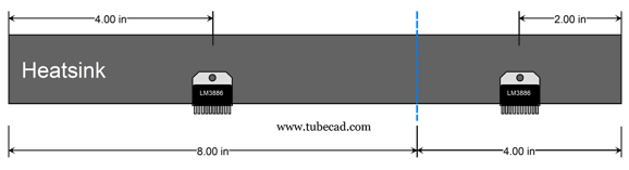
The tube-based amplifier draws 2A, as does the IMC, but the inverting amplifier must pass 4A. Effectively, both the tube-based amplifier and the IMC are working into an 8-ohm load, but the inverting amplifier works into a 4-ohm load. Since it delivers the same voltage, but twice the current, it must produce twice the power than either the tube-based amplifier or the IMC. In practical terms, this means that we should give the inverting amplifier twice the heatsink area as the IMC. For example, imagine a heatsink 12-inches long and two chip IC power amplifiers, such as the LM3886. We should place the IMC at 2 inches from the end and the inverting amplifier at 4 inches from the other end.
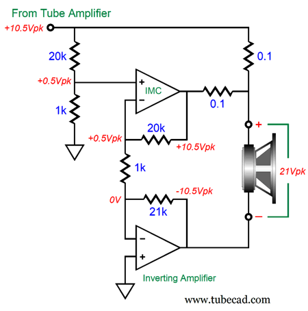
This arrangement allows the inverting amplifier to hog two thirds of the heatsink area. Speaking of LM3886 power OpAmps, the device could never be used in this circuit with its low gain of 1:2, as the LM3886 is not close to being unity-gain stable. The LM3886 is happiest with a gain over 1:10. The workaround is to decrease the two-resistor voltage divider ratio and increase the LM3886's gain.
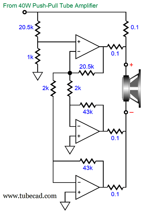
The input two-resistor voltage divider reduces the tube-based amplifier's output voltage to 1/21 its value, which the IMC and inverting power amplifier increase by 21 fold, thereby creating a voltage doubling across the loudspeaker leads. So far, this arrangement works well with 8-ohm loads, but not so well with 4-ohm loudspeakers. The workaround in this situation is to double up on the inverting power amplifiers.
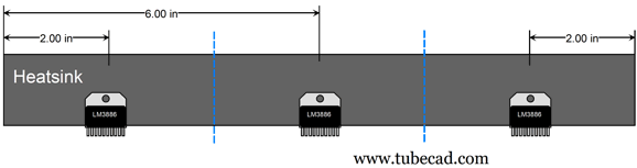
If you do the math, you will see that the loudspeaker sees twice the tube-based amplifier output and four times the power. The tube-based amplifier and each LM3886 deliver the same 25% of the power to the loudspeaker. In this situation, the heatsink division should be equal between the three LM3886 amplifiers.
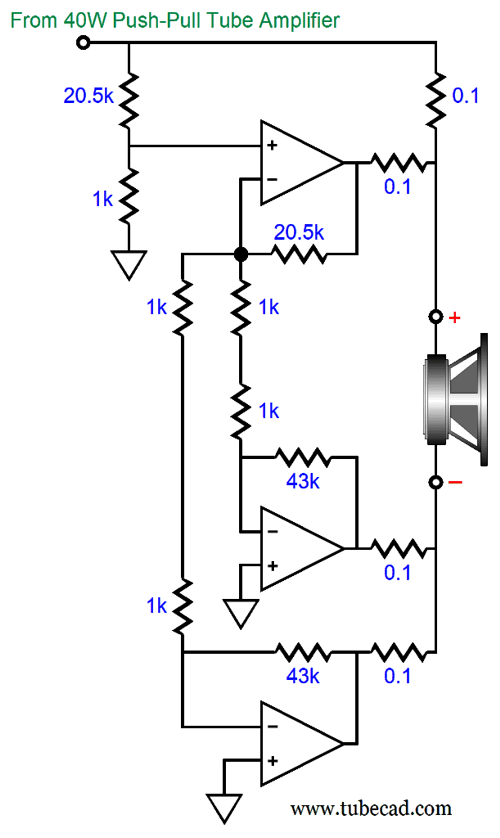
This layout assures that each LM3886 gets one third of the heatsink area. This equitable sharing of the heatsink brings a new problem: long PCB traces between the three LM3886 OpAmps. Of course, each LM3886 should get its own local power-supply bypass capacitors. I would, however, split the two 2k resistors into four 1k resistors.
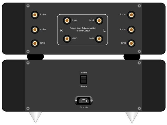
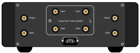
This way each LM3886 its own 1k resistor right next to its pins. (Think grid-stopper resistor.) Note that both inverting amplifier get a 0.1-ohm output resistor. Why? The resistors are there to absorb any small differences in the two inverting amplifiers outputs, as even 1% resistor can create slight imbalances. By the way, did you note the label that stated the input was from a 40W tube-based power amplifier? Since each LM3886 can deliver over 40W, the loudspeaker would receive 160W from this arrangement: 40W from the tube-based amplifier and 120W from the solid-state portion. Here is what the back of such an electronic component might look like.
In spite of the hulking power output, the chassis and heatsinks can be much smaller, as the LM3886 run comparatively cool at idle. There's no need to use 4-ohm and 8-ohm output post, as the circuit naturally, automatically conforms to either loudspeaker impedance. (I would still run a two-voltage bipolar power supply, +/-25Vdc and +/-35Vdc, with a selector switch to choose the lower voltage for 4-ohm loudspeakers and the higher voltage for 8-ohm loudspeakers.
Music Recommendation: Un Milagro de Fe Amazon Music Unlimited streaming service offers it in high-res, 24-bit and 96kHz .
//JRB
Did you enjoy my post? Do you want to see me make it to post 1,000? If so, think about supporting me at Patreon.
User Guides for GlassWare Software
For those of you who still have old computers running Windows XP (32-bit) or any other Windows 32-bit OS, I have setup the download availability of my old old standards: Tube CAD, SE Amp CAD, and Audio Gadgets. The downloads are at the GlassWare-Yahoo store and the price is only $9.95 for each program. http://glass-ware.stores.yahoo.net/adsoffromgla.html So many have asked that I had to do it. WARNING: THESE THREE PROGRAMS WILL NOT RUN UNDER VISTA 64-Bit or WINDOWS 7, 8, and 10 if the OS is not 32-bit or if it is a 64-bit OS. I do plan on remaking all of these programs into 64-bit versions, but it will be a huge ordeal, as programming requires vast chunks of noise-free time, something very rare with children running about. Ideally, I would love to come out with versions that run on iPads and Android-OS tablets.
|
I know that some readers wish to avoid Patreon, so here is a PayPal button instead. Thanks.
John Broskie
John Gives
Special Thanks to the Special 80 To all my patrons, all 80 of them, thank you all again. I want to especially thank
All of your support makes a big difference. I would love to arrive at the point where creating my posts was my top priority of the day, not something that I have to steal time from other obligations to do. The more support I get, the higher up these posts move up in deserving attention.
If you have been reading my posts, you know that my lifetime goal is reaching post number one thousand. I have 432 more to go. My second goal was to gather 1,000 patrons. Well, that no longer seems possible to me, so I will shoot for a mighty 100 instead. Thus, I have just 20 patrons to go. Help me get there. Thanks.
Support the Tube CAD Journal & get an extremely powerful push-pull tube-amplifier simulator for TCJ Push-Pull Calculator
TCJ PPC Version 2 Improvements Rebuilt simulation engine *User definable
Download or CD ROM For more information, please visit our Web site : To purchase, please visit our Yahoo Store: |
||||||||||||||||||||||||||||||||||||||||||||||||


| www.tubecad.com Copyright © 1999-2021 GlassWare All Rights Reserved |