| John Broskie's Guide to Tube Circuit Analysis & Design |
20 November 2022 Post Number 570
A Different Non-Gratuitous SRPP
Well, the word "assiduity" comes from the Latin verb assidēre "to sit beside." In his essay, The Advantages of Living in a Garret, Samuel Johnson proclaims that great thoughts are born at high altitudes:
Since I live at 5,003 feet above sea level, I suffer from no stagnation nor any creeping.
No doubt, hiking in the Alps and living in Colorado give rise to great ideas, but I would add to the list of inspiration–producing activities that of taking a shower, especially a nice steamy one that produces enough fog on the glass door to draw schematics with your wet finger. Yesterday, while washing my hair, an interesting idea hit me: why not use two stepped attenuators with an SRPP circuit, one before and one after? In a microsecond, the entire SRPP-based line-stage amplifier filled my mind. Most importantly, at least to me, the design qualifies as non-gratuitous. What does that mean?
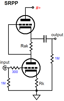
Most SRPP-based circuits are gratuitous, lazy affairs, wherein the SRPP isn't used to symmetrically deliver push-pull operation into a low-impedance external load—instead they are but indolent and unimaginative solution to the problem of what to do with the extra triode. What extra triode? Most small-signal audio tubes come in the twin-triode package, such as the 6AQ8, 6AS7, 6DJ8, 6H30, 6SN7, 12AT7, 12AU7, 12AX7, 5687, ECC99… The SRPP solves this "problem" magnificently, without the need for much thought.
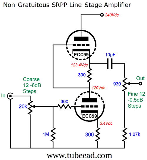
The SRPP topology, however, is load-dependant. In other words, we must optimize the circuit to work into a particular load impedance, usually a relatively low impedance, such as 300-ohm headphone drivers. Alternatively, we must optimize the load for a given SRPP. In other words, why not give the SRPP the load impedance it wants? I ran SPICE simulations to find the optimal load impedance for an ECC99-based SRPP circuit that used 300-ohm cathode resistors (unbypassed cathode resistors), which turned out to be 2k, which turned out to be higher than I expected, but it did conform to the old SRPP formula, Rak = (rp + 2rp)/mu. Nonetheless, we can easily design and make a stepped attenuator that presents a 2k load to the SRPP.
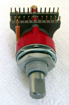
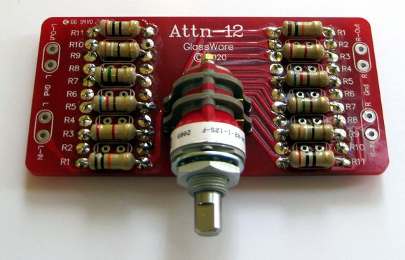
(Note that the 930-ohm stepped attenuator and the 1.07k resistor combine to create a 2k load.) Yes, volume potentiometers and fancy stepped attenuators usually appear in front of an amplifier, not behind it. Placing them, however, after the line-stage amplifier presents advantages and disadvantages. A big advantage is that the PSRR necessarily improves with greater attenuation. As we turn down the volume, we also turn down the power-supply noise that leaks out of the line amplifier's output. (The signal-to-noise ratio remains constant, however, as both the output signal and the amount of power-supply noise are attenuated equally.) In contrast, with the volume control in front of the line-stage amplifier, the PSRR remains constant, while the signal-to-noise ratio improves with higher signal output, but worsens with low volume settings. On the downside, placing the volume control after the line-stage amplifier must create a varying output impedance. The worst case scenario, assuming a near zero output impedance from the line-stage amplifier, is at -6dB of attenuation, as the output impedance will equal one fourth of the potentiometer or series stepped attenuator's input impedance. For example, if a 100k volume control is used, the output impedance will equal 25k ohms. On the other hand, the SRPP circuit does not deliver the low output impedance that cathode follower does, so a low-ohmage (2k) volume control following the SRPP will lower the output impedance over much of its range (if not all of it). In this design example, the output impedance ranged from 828 ohms to 725 ohms. The 10µF output coupling capacitor is needed due to the output 2k attenuator impedance. Although a 3.9µF capacitor is enough to extend the -3dB low-frequency fall off down to 20Hz, the 10µF capacitor takes it down below 10Hz. The input attenuator offers coarse -6 decrements, while the output attenuator delivers fine 0.5dB steps. The input and output stepped attenuators I had in mind are the Attn-12 types; the Attn-12 is a stereo 12-step attenuator that uses an American-made Grayhill two-deck, two-pole, 12-position rotary switch with hard-gold contacts.
Do not think of the two 12-step attenuators as offering 24 steps of attenuation, but as presenting 131 discrete steps of attenuation. In other words, we can vary the output signal by up to 65.5dB in 0.5 decrements. But with the coarse and fine attenuators, we are spared having to travel through all those tiny steps, as we need only spin the coarse knob first, then the fine knob. (I have found that -6dB decrements alone actually work well for most recordings.)
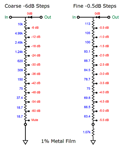
Here are the 1%, metal-film resistor values for each Attn-12.
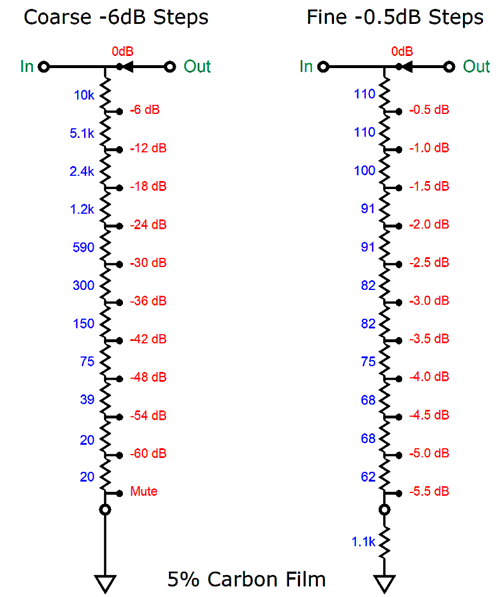
Now, the 5% carbon-film resistor values.
The assumption has been that we seek the lowest amount of distortion from the line-stage amplifier, which placing the coarse attenuator at the SRPP's input accomplishes nicely. This also assumes that either a regulated or a highly-filtered B+ voltage is employed. On the other hand, if we seek some juicy harmonic restoration, then flipping the attenuators position makes more sense. What would the resistor values be for the attenuators in this flipped setup? Easy. We multiply the fine values shown above by ten and divide the coarse values by ten. I ran SPICE simulations on the two approaches and found that with 1Vpk of output signal, the low-distortion version with the coarse attenuator in front of the SRPP provided -20dB less harmonic distortion than the alternative version with the fine attenuator in front. I would opt for the lower distortion, as I like the idea of building the Ultimate SRPP line-stage amplifier. Since the ECC99-based SRPP's PSRR is only about -10dB, not much in other words, I would use one of my PS-21 high-voltage regulated power supplies with two separate low-voltage regulators, so each ECC99 could get its own regulated heater power supply.
Of course, we could just as easily and far more cheaply use a 12Vac SRPP.
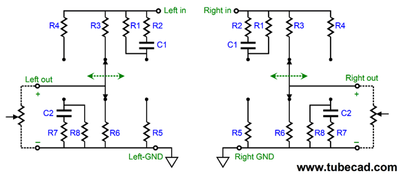
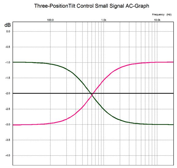
The 12Vac SRPP uses four cascading RC filters to deliver an extremely clean B+ voltage, albeit a much lower B+ voltage. With the 12Vac SRPP's B+ voltage of about 120Vdc, the cathode resistors must be increased to 340 ohms to work with the 2k load, due to the increased rp resulting from the lower ECC99 idle current flow. No matter which SRPP choice I made, I would also add a Tilt-2, which is a three-position tilt control designed for a 20k volume control. The Tilt Control entails a small signal insertion loss (-2dB), which is welcome, as the ECC99 delivers a gain of about 16dB in this design, while I prefer something closer to 12 dB in a line-stage amplifier.
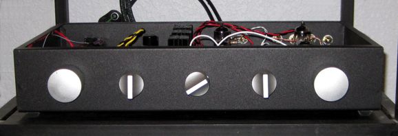
Some recordings need a little tilting of the frequency response to sound right. We would also need an input signal selector switch and power switch, which brings the knob count up to five, which would look something like the following.
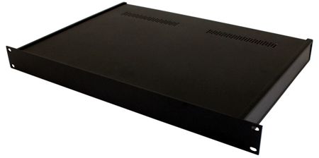
The enclosure shown is 17 inches wide by 3 inches tall and 10 inches deep, which is easily enough to house the power-supply transformers and PS-21 PCB. I would prefer the 2-inch-tall version, however. The actual SRPP circuit is so simple that chassis-mount tube sockets and point-to-point wiring could be used. If the 10µF output coupling capacitor proves two fat, we can place two thinner 5µF capacitors or three 3.3µF capacitors in parallel.
By the way, I once built a tube-based line-stage amplifier housed in a 1U 19-inch rack-mount chassis. I favored using 4µF output coupling capacitors at the time, but my favorite 400V polypropylene capacitor was far too fat to fit, so I placed four 1µF capacitors in parallel instead, each a different brand of polypropylene capacitor, with different means of construction, some with stacked film, others with spiraled film. In addition, I placed a 0.1µF film and foil capacitor (equally as large as the 1µF capacitors) in parallel with the other capacitors. I was amazed at how neutral the resulting sound was. My assumption was that the output signal would take the path of least obstruction, which would vary with frequency. It seemed to work out that way, as no band of audio frequencies seemed dimmed or boosted. Neutrality, much like sanity and stability, is sadly under appreciated. The eye and ear like to be dazzled—at first that is, but over time that which glitters and flashes or booms and sizzles soon irks.
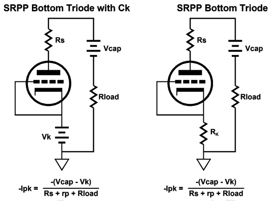
Further Cathode-Voltage
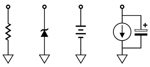
Of course, the cathode resistor could be replaced by a battery, a zener diode, or an IC voltage reference or, even, a constant-current source (as long as it is bypassed by a large-valued capacitor).
The cathode voltage and the current flow through the cathode define how power will be dissipated just in creating a cathode-bias voltage. This power loss serves no other purpose than to establish a positive cathode voltage. I argue that we can put this voltage, no matter how trivial, to additional use.
Well, solid-state devices can work with the tiniest B+ voltages; if they couldn't, hearing aids, smart phones, and watches would be impossible. Most OpAmps intended for audio use work best with bipolar power supplies between ±12Vdc to ±22Vdc. Of course, these same OpAmps could also be used with monopolar power supplies between 24Vdc to 44Vdc. Now, 44Vdc is a crazy high cathode voltage for common audio tubes, such as the 6DJ8 and 6SN7, but not for power output tubes. In fact, cathode-bias voltages in the 60Vdc to 80Vdc range are not uncommon with output tubes like the 6AS7 and 300B.
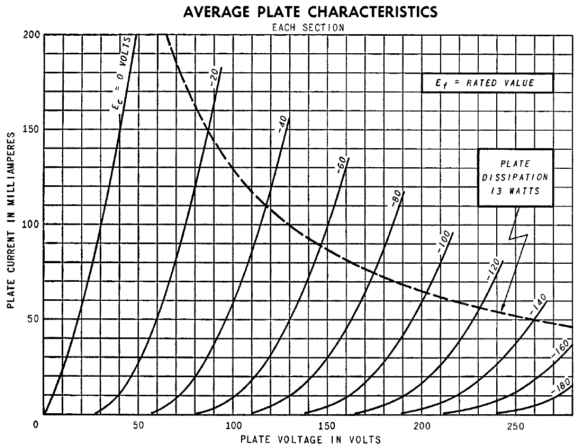
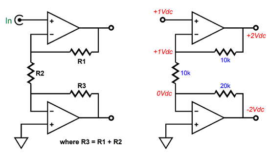
6AS7 Plate Curves One thing to consider is that if the solid-state audio circuit that we stuff into the cathode-bias voltage is going to present a DC output voltage half that of the cathode voltage, then we have effectively halved the grid-to-cathode voltage, so twice the bias voltage will be needed to return to the target idle current. In other words, this gives us more cathode voltage to exploit; for example, if the tube normally required a cathode-bias voltage of 4Vdc, then we can double this voltage and sneak a solid-state circuit inside this expanded voltage window of 8Vdc. Okay, let's move on to actual circuit examples. The following circuit is a simple unbalanced-to-balanced amplifier that holds a non-inverting and an inverting amplifier to produce a balanced pair of output signals. The example on the right shows how the 1V input signal gets amplified by 2 and -2 by the amplifiers. The bottom amplifier's inverting input effectively serves as "ground" for the top amplifier's negative feedback loop. The top amplifier's gain is set (R1 + R2) / R2; the bottom amplifier's gain, R3/R2. The output-to-output gain is twice the gain of one of the amplifiers.
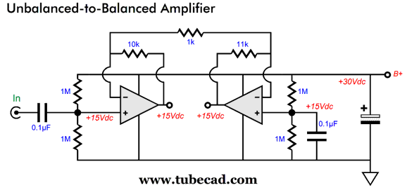
Let's now rearrange the circuit horizontally.
The four 1M resistors simply halve the B+ voltage. The 0.1µF capacitor on the left is the input coupling capacitor and the capacitor on the right is an AC shunting capacitor that eliminates the resistor noise from being amplified by the right inverting amplifier. The gain is 1:11 and 1:-11, making a differential output gain of one to twenty-two.
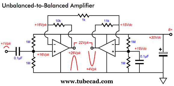
A 1Vpk input signal forces the left non-inverting amplifier's output to swing up by an extra 11 volts, while the right inverting amplifier's output swings down by 11 volts. Now, let's plug this circuit into a bigger hybrid circuit.
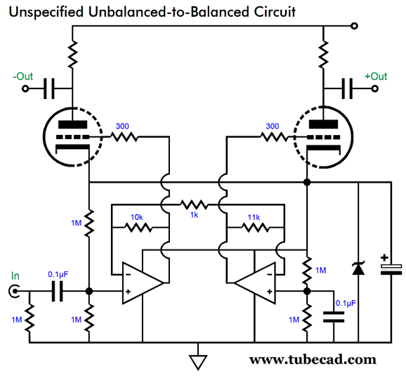
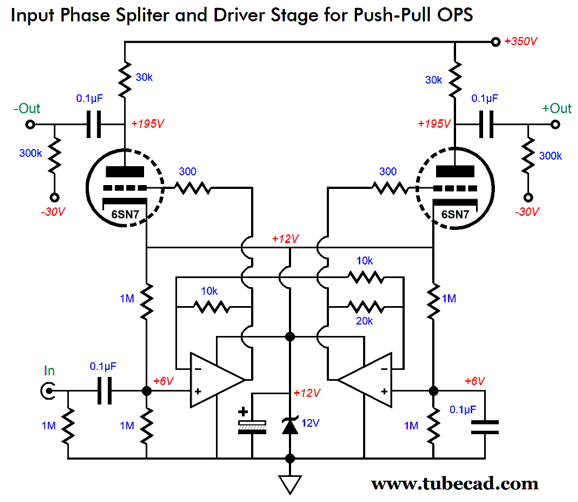
The two triodes are driven by the OpAmp-based unbalanced-to-balanced amplifier below. The triode grids DC couple to the OpAmp outputs, so the triodes see a cathode-bias voltage equal to half the zener voltage. To what audio uses could we put this hybrid circuit? How about as the frontend of a push-pull tube-based power amplifier?
The solid-state circuit functions as a low-gain phase splitter that drives the 6SN7 triodes that will (in turn) drive the two output tube grids. One volt of input signal becomes four volts of differential output signal from the OpAmps. If more gain is needed, we only need to change the OpAmp negative feedback resistor values. Note that no global negative feedback loop is employed, making this tube-based power amplifier a feedback-free design. Adding a negative feedback loop is easy enough, as the right OpAmp's non-inverting input can be used as the negative feedback input.
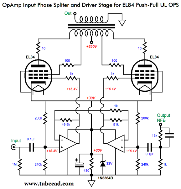
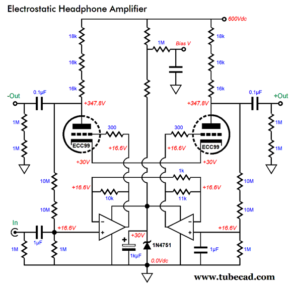
Note that the four 1M voltage-divider resistors have been replaced by 200k and 240k resistors. Why? Tubes are easier to turn on to great current conduction than they are to turn off. In other words, we need to be able to swing more negatively than positively when driving their grids in order to get symmetrical current swings from the tube. Also note that the unbalanced-to-balanced amplifier's gain has been increased substantially. Why? We need to have a much higher open-loop gain to power the negative feedback loop. The closed-loop gain is equal to (16k + 1k)/1k or 1:17, but the open-loop gain will prove much, much greater, as the unbalanced-to-balanced amplifier's gain is equal 1:51. Another possible audio use for this topology is that of a hybrid electrostatic headphone amplifier.
The unbalanced-to-balanced amplifier drives two ECC99 triodes that capacitor couple to the electrostatic stators. DC negative feedback is provided by the 10M resistors in series. In other words, the solid-state unbalanced-to-balanced amplifiers below the triodes control the triode DC plate voltages, keeping both in line with each other. The two 1µF capacitors may seem excessively large in value, but the relatively high capacitance is needed to provide a slow turn-on for the triodes, as the 10M resistors will slowly charge up the capacitors, which allows the triodes to slowly ramp up to full current flow.
Exploiting SE OPS Cathode Voltage Let's start with a simple hybrid single-ended power amplifier design.
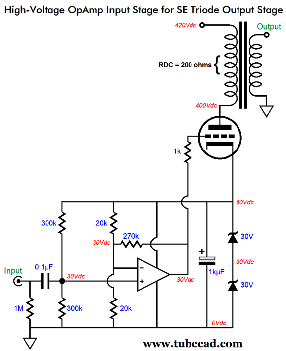
The two 30V zener diodes in series establish a 60V cathode voltage. Why not use a single 60V zener? Heat. Excessive heat production for the typical 5W zener. Using two 5W zener diodes in series effectively creates a 10W 60V zener. The 1kµF capacitor shunts the pair of zener diodes and effectively AC grounds the cathode. The OpAmp used must be a high-voltage type, such as the OPA445. The OpAmp's gain is equal to (270k + 20k||20k) / (20k||20k) or (270k + 10k) / 10k or 1:28 or, roughly, +29dB. In other words, 1V of peak input signal would prompt 28V of peak output voltage swing from the OpAmp, which should be enough to fully drive the output tube, say a triode connected KT88 or a pair of parallel EL34s. Indeed, we can achieve auto-bias by replacing one of the zener diodes with a constant-current source.
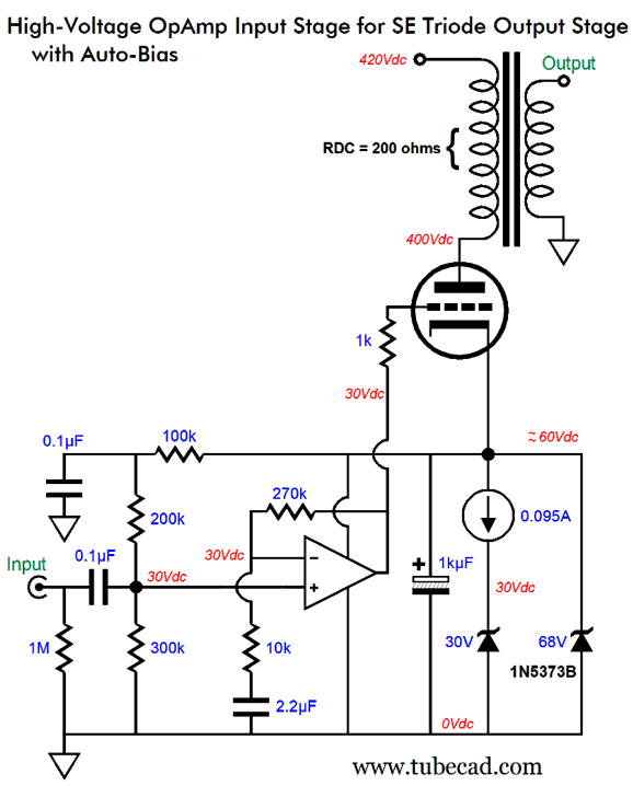
The 95mA constant-current source will adjust the cathode voltage until 100mA flows through the output tube, assuming that 4mA flows through the OpAmp and 1mA through the 300k, 200k, and 100k resistors. The 68V zener is there only to prevent the OpAmp from seeing too high a B+ voltage. The 30V zener is there halve the constant-current source dissipation and to allow us to use an LM317-HV regulator in the constant-current source circuit. (The LM317-HV regulator offers a 57V voltage limit.) Note that the two 20k negative feedback resistors have been replaced by a single 10K resistor, which is terminated by a 2.2µF film capacitor. An alternative approach to auto-bias is to place a cathode resistor in series with the zener string.
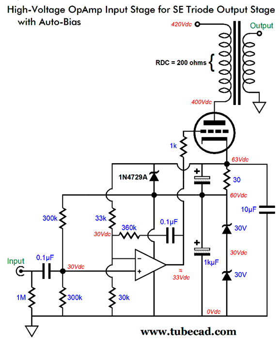
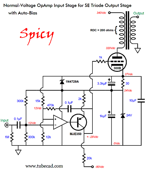
The 30-ohm cathode resistor will experience a 3V voltage drop when the triode draws 100mA of current. The 33k and 30k resistors form a two-resistor voltage divider that will only center at 30Vdc when the cathode voltage is 63Vdc and the tube draws 100mA. Remember that an OpAmp will strive to maintain equal voltages at both of its non-inverting and inverting inputs, so it will adjust its output voltage until the two inputs see the same voltage. Thus, the OpAmp will auto-bias the output tube for us. The 1N4729A zener breaks at 3.6V, which will both protect the bypass capacitor shunting the 30-ohm cathode resistor and apply a hard brake on the possible single-ended rectification effect. The OpAmp's gain is close to the previous example's gain of 1:24. One idea that might work out is to use a normal-voltage OpAmp with PNP transistor to create the huge grid-voltage swings needed to drive a 300B or other weak transconductance output tube.
The OpAmp works with a differential power-supply voltage of 24Vdc. The high-voltage PNP transistor is configured in the common-emitter topology with its collector resistor terminating into a -80Vdc power-supply rail. The 300B requires a cathode-to-grid bias voltage of about -55Vdc to establish an idle current flow of 100mA with this cathode-to-plate voltage differential. The only negative feedback employed, however, is that provided by the 300B triode's plate resistance; still, my fear is that this design might work well in SPICE simulations, but prove unstable in reality. For example, what happens at startup, when the 300B is cold and not conducting? Will it ever begin to conduct any current, as its grid voltage will be stuck at -80Vdc? Perhaps all that is needed is a bleeder resistor that attaches to the B+ voltage and terminates into the 300B's cathode, as the resistor will provide a trickle of current at all times, which could bring up the OpAmp power-supply voltage sufficiently for it to engage the PNP transistor. Alternatively, we can apply a negative feedback loop to the output tube's plate, so the OpAmp can not only establish DC auto-bias, but also control the output tube's AC current conduction. The trick is to confine the negative feedback loop to the primary side of the output transformer. Wouldn't extending the feedback loop to the output transformer's secondary provide even lower distortion? It would—in theory. In practice, the phase shifts from the primary to the secondary are a pain when global negative feedback is employed. In contrast, extending the negative feedback loop only to the output tube's plate is far easier to pull off successfully. In fact, we can use the primary's DC resistance (DCR) in place of a cathode resistor as the current-sense resistor.
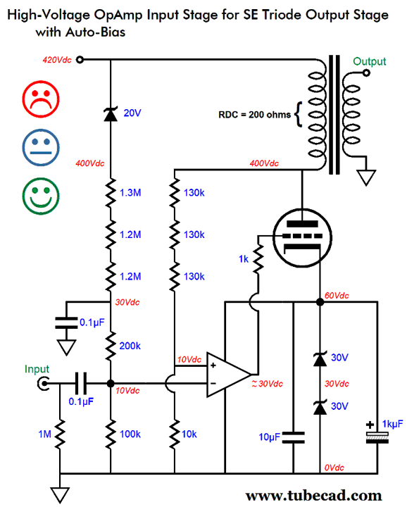
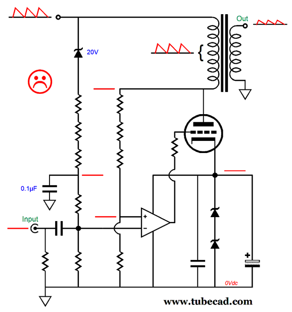
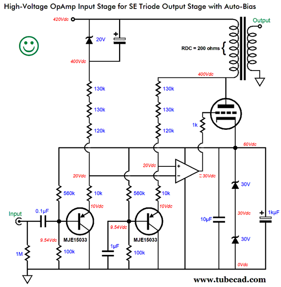
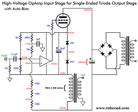
A 100mA idle current flow through the primary DCR of 200 ohms produces a voltage drop of 20Vdc, the same as the 20V zener's voltage drop. The two many-resistor voltage-dividers only deliver the same DC output voltage when the output transformer's primary sees the same 20V voltage drop, which the OpAmp will strive to realize. The OpAmp and the output tube form a non-inverting two-stage amplifier, which explains why the OpAmp looks as if it were being used upside-down. It isn't. A positive-going input signal will force the OpAmp's output to swing negatively, which will force the output tube's plate to climb in voltage as the tube draws less current. In other words, the plate follows the input signal's phase. The three 130k and 10k resistors set a gain of 1:40 from OpAmp input to output tube plate. Assuming a plate-voltage swing of ±240Vpk to achieve full power output, the OpAmp will need to see an input signal of ±6Vpk, which a "hot" tube-based line-stage amplifier can easily deliver. The three faces denote that that arrangement might disappoint or prove adequate or shine—all depending on the how clean the B+ voltage is. If the B+ voltage is tightly regulated, then the happy face applies; if just well filtered, then the okay face applies; and if ripple polluted, then the sad face applies. The potential problem arises due to the negative feedback loop creating a clean output at the plate—clean relative to ground, but not to the B+ voltage. An output transformer is a differential device, so if the primary sees no ripple at the plate connection, but 100% of the ripple at the B+ voltage connection, then the ripple becomes an unwanted signal that will be passed along to the secondary and the loudspeaker. Of course, if the B+ voltage is completely ripple free, then the secondary will also prove ripple free.
I came up with a workaround back in post 314, which ensured that no power-supply noise appeared across the output transformer's primary.
The OpAmp works to ensure that the output tube does not react to the ripple present on the B+ voltage, dynamically varying the grid voltage so that the triode draws a constant current in spite of the B+ voltage fluctuations. Let's flesh-out this design.
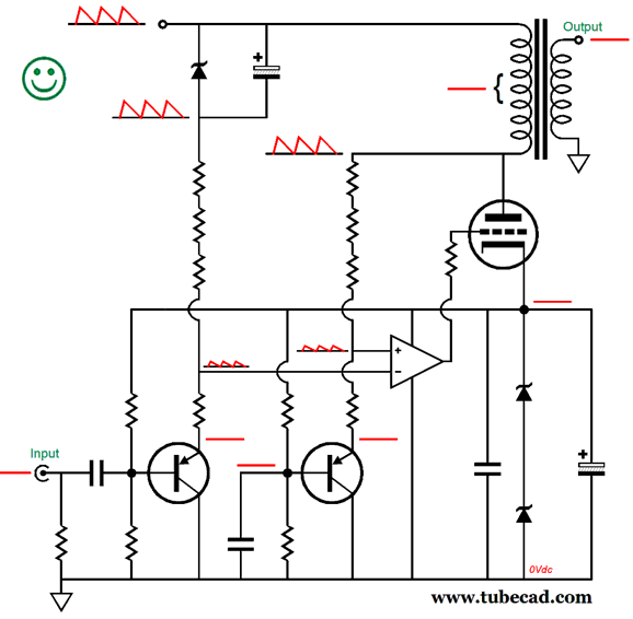
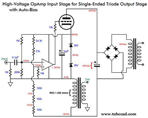
The two PNP transistors present no ripple at their emitters, so the emitter's effectively function as AC "grounds" for the two equal-valued four-resistor voltage divider strings. The result is that all the power-supply noise appears on the both ends of the primary, so no power-supply noise appears on the secondary.
The input signal is reduced by 38/39 or 0.974; in addition, the input signal is contaminated by 1/39th of the power-supply noise, which will be amplified by the OpAmp and output triode's combined gain of 39 to 100% at the plate. Yes, it does seem paradoxical that we must add noise to eliminate noise; nonetheless, it works. If we are assured that the B+ voltage is noise-free, we could try the following design, which uses a 300B output tube.
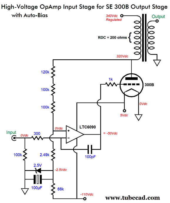
The high-voltage OpAmp drives the 300B's grid DC directly, so it controls its idle current flow. In addition, no input coupling capacitor is needed. The 2.5V zener diode (LM431 shunting voltage reference IC) works as the amplifier's voltage reference and it establishes a -2.5V power-supply rail voltage. The final gain at the plate is 1:129, so less than 2Vpk will drive the amplifier to full output. The 300-ohm resistor and the 100pF capacitor are there to help stabilize the OpAmp and limit the high-frequency bandwidth. (The negative feedback loop string of three resistors might need a few pico-farads of shunting capacitance as well.) An alternative workaround is to stand the output stage on its head.
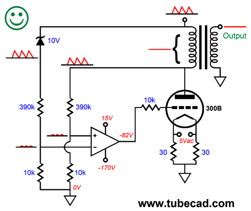
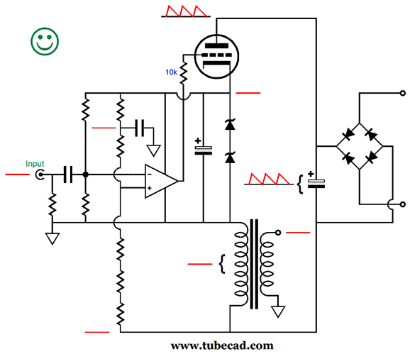
The power supply is no longer grounded, but free to float. This means that, in a stereo power amplifier, each channel will need its own separate high-voltage power supply. This also means the power transformer's center-tap is no longer terminated into ground, a setup that which simply melts many a solder-slinger's mind, so this inverted topology is best left to the mentally flexible. In this setup, the OpAmp now strives to produce no power-supply noise at the bottom of the primary. Since the ground presents no power-supply noise and since the other end of the primary sees no power-supply noise, the secondary is blind to the power-supply noise.
Auto-bias is still achieved, as the primary DCR is still used as current-sense resistance to monitor the current flow through the output tube. To quickly see how this works just imagine the output tube drawing too much current, which would increase the voltage drop across the primary DCR, which in turn would force the OpAmp's non-inverting input to see a negative voltage relative to its inverting input, and the output stage' output would swing negatively, causing the output tube to decrease its current conduction. If the tube draws too little current, the non-inverting input goes positive, which forces its output positive, which in turn increases the tube's conduction. Here is a variation that loses a capacitor and gains a resistor.
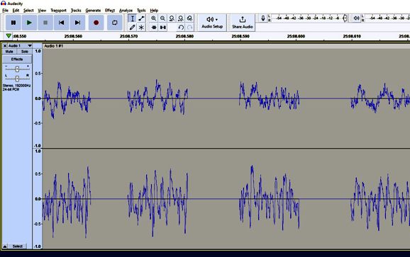
Music Recommendation: Qobuz Update
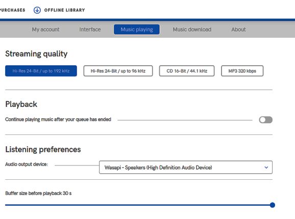
Those three gaps should never be there. By the way, I could readily hear gaps that lasted only 4 milliseconds. I set the Qobuz app to use a 30-second buffer before playing the music.
It did not, however, seem to have any effect. I discovered that if I used my main computer that that attaches to the fiber-optic DSL through a network cable, not WiFi, and that if I first download ("import") the album into the Qobuz "Offline Library," the music emerged faultlessly. The download is amazingly fast, a few minutes for most albums. Still, all of this is a pain. In other words, if Amazon Music offers an album at the same resolution as Qobuz, I listen to Amazon Music; if Qubuz offers a higher resolution version, I do the work to hear it with Qobuz. By the way, it seems as if every few weeks the Amazon Music app delivers the following notice:
I always press the "Update Now" button. The next step, which I have forgotten to do a few times is to recheck the audio playback options.
Be sure that the update didn't set (or reset) your option choices to some middle-brow default setting. For example, I never want to add any loudness normalization (compression).
//JRB
Did you enjoy my post? Do you want to see me make it to post 1,000? If so, think about supporting me at Patreon.
User Guides for GlassWare Software
For those of you who still have old computers running Windows XP (32-bit) or any other Windows 32-bit OS, I have setup the download availability of my old old standards: Tube CAD, SE Amp CAD, and Audio Gadgets. The downloads are at the GlassWare-Yahoo store and the price is only $9.95 for each program. http://glass-ware.stores.yahoo.net/adsoffromgla.html So many have asked that I had to do it. WARNING: THESE THREE PROGRAMS WILL NOT RUN UNDER VISTA 64-Bit or WINDOWS 7, 8, and 10 if the OS is not 32-bit or if it is a 64-bit OS. I do plan on remaking all of these programs into 64-bit versions, but it will be a huge ordeal, as programming requires vast chunks of noise-free time, something very rare with children running about. Ideally, I would love to come out with versions that run on iPads and Android-OS tablets.
|
I know that some readers wish to avoid Patreon, so here is a PayPal button instead. Thanks.
John Broskie
John Gives
Special Thanks to the Special 79 To all my patrons, all 79 of them, thank you all again. I want to especially thank
All of your support makes a big difference. I would love to arrive at the point where creating my posts was my top priority of the day, not something that I have to steal time from other obligations to do. The more support I get, the higher up these posts move up in deserving attention.
If you have been reading my posts, you know that my lifetime goal is reaching post number one thousand. I have 430 more to go. My second goal was to gather 1,000 patrons. Well, that no longer seems possible to me, so I will shoot for a mighty 100 instead. Thus, I have just 21 patrons to go. Help me get there. Thanks.
Only $12.95 TCJ My-Stock DB
Version 2 Improvements *User definable Download for www.glass-ware.com
|
|||


| www.tubecad.com Copyright © 1999-2021 GlassWare All Rights Reserved |