| John Broskie's Guide to Tube Circuit Analysis & Design |
25 September 2022 Post 567 New Ladder Attenuator
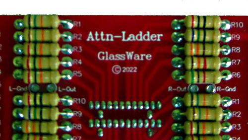
New Attn-Ladder
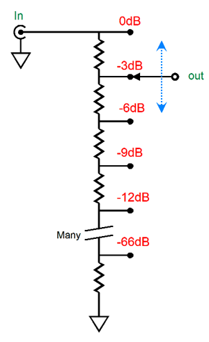
A ladder attenuator is nothing like a potentiometer. Perhaps you have seen the small fixed attenuator plugs that hold one male RCA plug and one female RCA jack and two fixed resistors inside a small barrel; these fixed attenuators are useful when bi-ampping and one of the amplifiers offers too much voltage gain. Now, imagine a bunch of these fixed attenuators and some means of selectively swapping the right one in place.
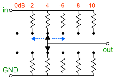
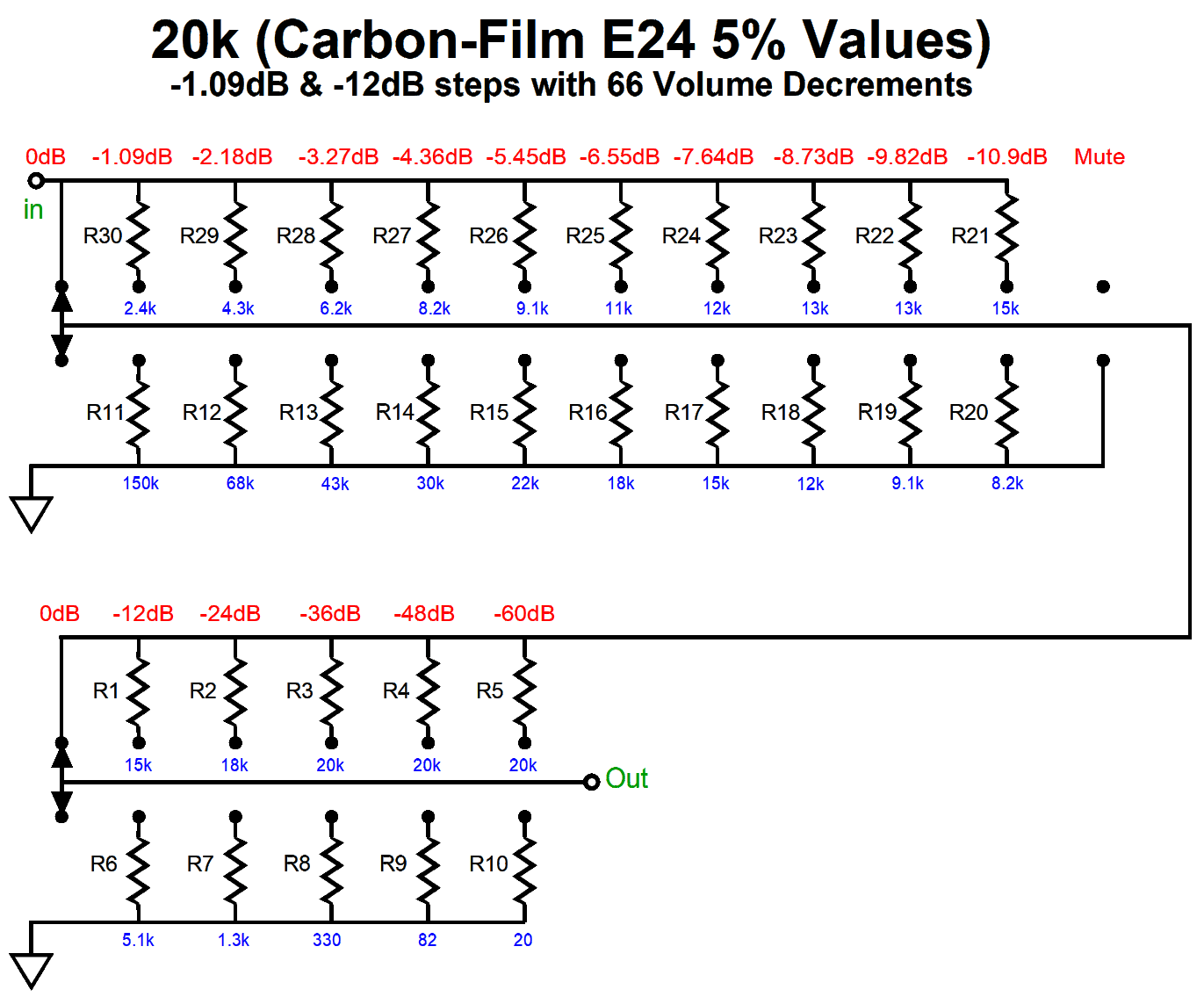
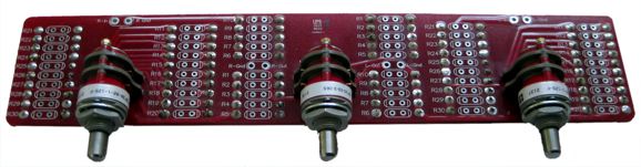
The ladder improves upon the series attenuator by setting up an array of many two-resistor voltage dividers and the means to switch to the desired pair. Now we are back to just three solder joints and just two resistors in the signal path—but at the cost of twice the switch contacts and twice the resistors used. This is the no-compromise approach to stepped attenuator design. The downside to this attenuator topology is that twice as many resistors and switch poles are needed. In other words, a comparable series attenuator will cost half as much as the equivalent ladder attenuator. In the Atten-Ladder, two ladder attenuators cascade, one with fine decrements of volume, one with coarse steps. The result is 66 steps of possibile attenuation in 1.09dB decrements, for a total of 70.9dB of maximum attenuation. Here is the schematic for one of the two channels.
The Atten-Ladder holds three gold-contact rotary switches. The center switch works for both channels and offers -12dB steps of attenuation. The two flanking switches deliver fine 1.09dB steps of attenuation, one for each channel. In other words, we have a built in balance control, as we can easily alter one channels volume independant of the other. In addition, each flanking switch offers a hard mute, which I find essential when testing for problems in my system.
Another change over the Attn-1 is that I mounted the switches on the bottom of the PCB. Why? The rotary switches hold a flat on their shaft that should have appeared 180 degrees around on the shaft to have the knob indicator align with our expectations. The Atten-Ladder is now availble at the GlassWare web store. The kit can be bought with or without the resistors.
More Cathode Voltage Exploitation
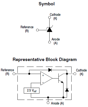
(If the labeling of its cathode and anode seems contradictory to that of a triode's cathode and anode (plate), it is due the inclusion of the diode in parallel with the NPN transistor. Solder a TL431 in backwards and you get a forward-biased diode.) The internal voltage reference develops a 2.5Vdc voltage drop, which the internal OpAmp than compares to the cathode voltage, making adjustments to the NPN transistor's base voltage to bring the cathode voltage in line with the 2.5V reference voltage. A shunt regulator, in other words. Well, the internal OpAmp can be used as an amplifier.
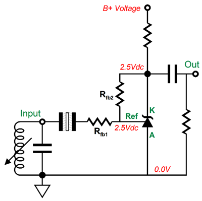
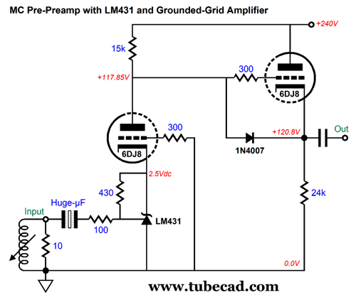
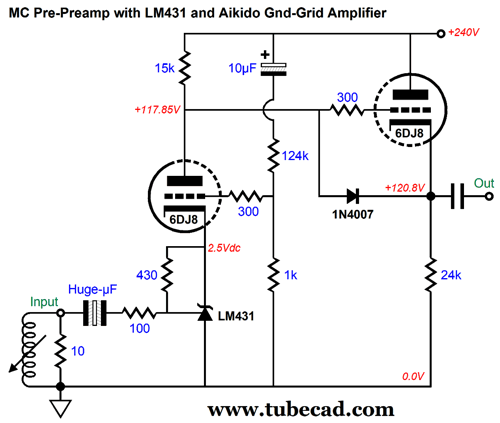
The 431 is configured as an inverting amplifier here, with its gain set by the ratio of Rfb2/Rfb1. The way it works is that the 431's internal OpAmp strives to see a fixed 2.5Vdc voltage at the 431's reference adjustment pin; the only way this is possible is to vary the voltage at the 431's cathode so as to "zero" out the AC signal at nexus of the two negative feedback resistors and the reference adjustment pin. Here is a design example that pre-amplifies the weak signal from an MC phono cartridge and drives a grounded-grid amplifier's cathode, resulting in far greater gain than the 6DJ8 could deliver in a grounded-cathode amplifier topology.
The negative feedback resistors, 100 and 430 ohms, set a gain of 1:4.3 (+12.7dB), which the 6DJ8 then amplifies to 1:100 (+40dB) at its plate. The assumption here is that the cathode follower will drive a passive RIAA equalization stage, which will incur a -20dB insertion loss that will be made up by the following gain stage. If the following gain stage also delivers a gain of 40dB, the phono preamplifier's final gain will be 60dB, as 40dB minus 20dB plus 40dB equals 60dB. What is missing is Aikido mojo. The grounded-grid amplifier's grid is merely grounded in this circuit. What if we put it to some further use by injecting a small sampling of power-supply noise, thereby causing a power-supply noise null at the output? Well, we will have achieved Aikido mojo.
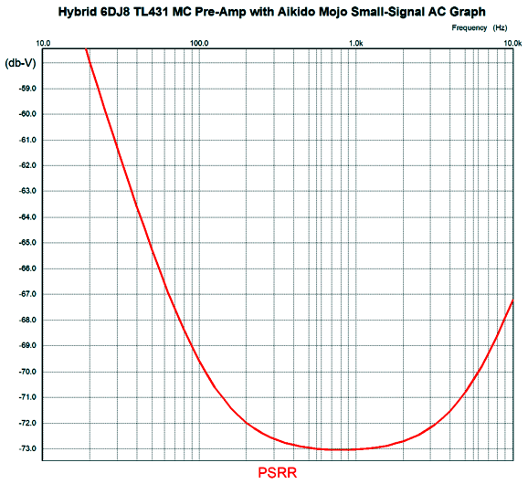
The 124k and 1k resistors form a two-resistor voltage divider that leaks a tiny amount of ripple, only 125th of it. This small amount of ripple, however, results in an impressive PSRR of -70dB at 100Hz.
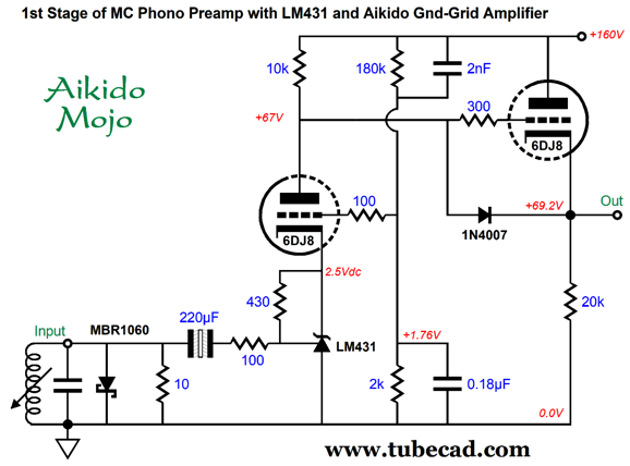
The larger the terminating capacitor value, the lower down in frequency the power-supply-noise null extends. What if we lose the terminating capacitor, opting for an AC and DC two-resistor voltage divider?
Note the lower B+ voltage and the 10k plate resistor. We see a DC two-resistor voltage divider here, the 180k and 2k resistors. We also see two AC voltage dividers, the two resistors and the two capacitors, 2nF and 0.18µF. Note the inversion of the capacitor values relative to the resistor values. The capacitors are some delicious frosting on the two-resistor voltage divider, as they shunt the resistor noise and improve the high-frequency power-supply-noise null. The added MBR1060 diode is there to protect the delicate MC cartridge's coils at startup and shutdown. It may not be needed. In SPICE simulations, the peak DC voltage the coil experienced at startup was 18mV; at shutdown, 92mV; both were brief. With an MC pre-preamp, we are fighting for two goals: low distortion and low noise. Often, we must choose one over the other. In this circuit, the values of two negative feedback resistors are important. If we use 10-ohms and 43-ohms, we get lower resistor noise, which is a good thing, but we also get higher distortion, as the 43-ohm resistor loads down the LM431 excessively. If we use 1k and 43k, we get truly low distortion, but the resistor noise goes way up. Thus, the 100-ohm and 430-ohm resistors are a compromise between low noise and low distortion. In addition, the lower the resistor values, the bigger the input coupling capacitor must be. By the way, they make adjustable shunt voltage references with an internal voltage reference of only 1.24V, such as the TLV431. The lower internal reference voltage would allow us to use either a lower B+ voltage for the 6DJ8 triode or higher-mu triodes, such as the 6AQ8, 6N1P, 6SL7, 12AT7, 12AX7, 12AY7, 5751, 6072. Next time, we will look at circuits that use discrete transistors.
Doubling a 300B SE Amplifier's Output One way to think about it is to imagine a stereo 8W per channel 300B-based single-ended power amplifier, which we decide to parallel to create a 16W monoblock power amplifier. We wire up the two 300B output tubes in parallel, tying the cathodes, grids, plates together. We parallel connect the output transformer's primary and secondary together. Will this mono power amplifier deliver 16W into the 8-ohm loudspeaker? It will, but only if we connect the speaker to the output transformer's 16-ohm output tap, not the 8-ohm tap. If we use the 8-ohm tap, we only get 8W (possibly less) of power output. What went wrong? When we paralleled the two amplifiers, we failed to parallel the two 8-ohm loudspeakers, which would have created a 4-ohm load, which would develop 16W into the 4-ohm load—when attached to the 8-ohm output tap. What if we paralleled three 8W amplifiers, then we would be screwed, as none the output transformer taps deliver enough output voltage swing to produce 24W of output power into an 8-ohm load. (If for some amazing reason the transformer offered a 24-ohm tap, we would get our 24W of output.) When we lower the output tube(s) plate resistance (rp), we must also lower the primary impedance, which means lower the winding ratio. When we use the 16-ohm transformer tap, we effectively lower the winding ratio the square root of 2; when we use the 4-ohm transformer tap, we effectively raise the winding ratio the square root of 2.
If some company decided to make a 32W single-ended power amplifier that held four 300B output tubes, and if the company wanted to the retain the standard three ohmage output taps of 16, 8, and 4, then the output transformer would need to be wound to a lower winding ratio. (In this example, the winding ratio must be exactly half that of the 8W output transformer, as the impedance ratio is equal to the square of the winding ratio. The square root of 0.25 is 0.5. We want to quarter the primary impedance, so we must half the winding ratio.) Is that a huge liability? No, the contrary. The lower the winding ratio, the better the output transformer's performance, all other variables held constant. The optimal ratio for a signal transformer is 1:1, as the capacitive coupling will match the inductive coupling ratio of 1 to 1. A 10k transformer holds a staggeringly big winding ratio. The winding ratio of a 10k to 8-ohm output transformer is 35:1, as 8 x 35² = 10,000. Since a winding ratio of 35:1 requires 35 times more turns of wire in the primary than in the secondary, the wire used must be very thin indeed, which brings with it a far higher DC resistance, which in turn wastes potential output power, as the high-resistance wire will get hot. Okay, what if we cannot afford twice as many 300B output tubes, nor the bigger and more expensive power and output transformers?
The cheaper workaround is to go hybrid, wherein solid-state helps vacuum-state put out more power. Hybrid amplifiers take many forms and variations. At one extreme of design philosophy, the tube delivers no power into the loudspeaker, only the drive signal for a solid-state power amplifier. This is a cascading arrangement, with a tube-based signal amplifier spilling into a solid-state power buffer or amplifier, like a plowman steering his ox.
An alternative approach is to place the tube-based power amplifier in parallel with a solid-state power buffer or amplifier.
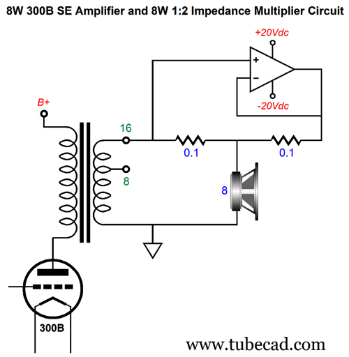
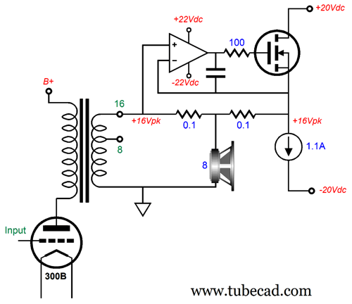
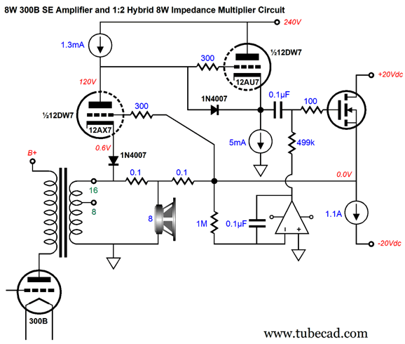
The solid-state power buffer sees the output signal from the 300B single-ended power amplifier's secondary and delivers the same signal to its 0.1-ohm power resistor. Thus, the output signals from both amplifiers are identical and sum at the conjunction of the resistors and the loudspeaker. This is an impedance multiplier circuit (IMC) that effectively doubles the load impedance the 300B amplifier works into, so the connection is made to the 16-ohm output tap, not the 8-ohm tap, in spite of the loudspeaker impedance being 8 ohms. We assume a reasonable 8W of output from the 300B amplifier, so the solid-state power buffer must at least match this amount of output power. To deliver 16W into an 8-ohm load requires 16Vpk and 2Apk of output, so both the 300B single-ended amplifier and the solid-state power buffer must be able to deliver 16Vpk of output voltage swing (but only 1A of peak current flow), which explains the +/-20Vdc bipolar power-supply-rail voltages. With this unconventional arrangement, we can vary the ratio of contribution from the different technologies. For simplicity's sake, let's stick to a ratio of 1:1, although other ratios are possible.
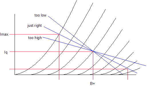
Imagine that you are asked to lift a 50lbs sack of sand. If someone else helps, lifting just as hard as you do, the sack effectively weighs 25lbs for each of you. Now, if a solid-state power amplifier delivers the same output voltage and output current as the tube-based power amplifier, the loudspeaker's impedance will effectively double, as far as both amplifiers are concerned. Why did weight halve, but impedance double. Resistance is the positive way of stating a negative, as resistance a negative attribute; its inverse positive attribute, i.e. conductance, is a positive labeling of a positive attribute. As far as both amplifiers are concerned, the loudspeaker's conductance halved so only half the output current is needed. This is an important consideration, as the nominally 3k primary impedance on the single-ended output transformer will now reflect 6k, not 3k. Unlike most push-pull power amplifiers, single-ended power amplifiers demand careful setting of their idle current, if we expect the maximum amount of output power delivered into the external load. The perfect amount of idle current for a 3k load, given the same B+ voltage, cannot be the optimal current flow for a 6k load. (See post 364 for more information on this topic.)
This is why tube-based power amplifiers hold output transformers with taps for 16, 8, and 4-ohm loads. In short, for the 3k output transformer to work in this hybrid configuration that effectively doubles the load impedance, the 16-ohm output tap must be used with an 8-ohm load; the 8-ohm tap, with a 4-ohm load.
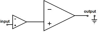
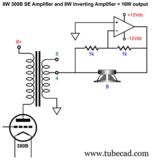
What if a preexisting 8W 300B single-ended power amplifier only offers 8- and 4-ohm output taps? Then we can only use 4-ohm and 2-ohm loudspeakers with the power-doubling circuit based on the 1:1 IMC. On the other hand, if we replace the IMC with an inverting power amplifier, we could double the 8W into 8-ohm loudspeakers.
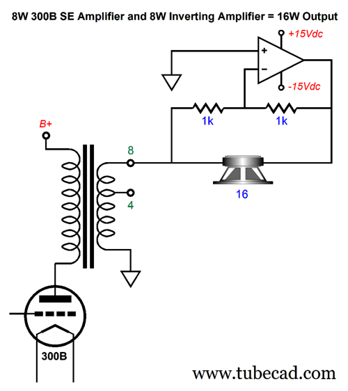
(Note that the two amplifiers are in series, not in parallel.) The unity-gain inverting power amplifier gets its input signal from the 4-ohm output tap and inverts it at its output. The 8-ohm loudspeaker then sees twice the 4-ohm-tap output voltage across its leads, which results in 16W of power delivery. As far as the 300B amplifier is concerned, it is driving a 4-ohm loudspeaker. Where the power-doubling circuit based on the 1:1 IMC effectively doubles the speaker impedance, this arrangement halves it. Both arrangements make use of the output transformer impedance taps to achieve power doubling. Note that 16-ohm loudspeakers cannot be used with the power-doubling circuit based on the 1:1 IMC, as no 32-ohm tap exists on the output transformer. Likewise, 4-ohm loudspeakers cannot be used with the power-doubling circuit based on the inverting power amplifier power-doubling arrangement. While 4-ohm loudspeakers are common, 16-ohm loudspeakers are rare, very rare. If you own an old horn-loaded 16-ohm speaker, the following arrangement would work to double the output power.
Returning to the IMC-based power-doubling arrangement, where do we buy an 8W solid-state power buffer? Sadly, no one makes a unity-gain-stable power buffer in the same package as the LM1875 (or LM3886) that can deliver 1A of peak output current swing. We can use an LM3886 configured as an amplifier with a gain of 10 and then use a 1/10th voltage divider at its input to create a unity-gain power buffer, but we would be throwing away negative feedback. One workaround is to build a power buffer out of discrete parts. No doubt, something like a discrete power diamond circuit comes to the reader's mind, but I was thinking more along the lines of a single-ended power buffer. Why? Might as well match the single-ended 300B amplifier with a single-ended power buffer—like for like; single-ended for single-ended.
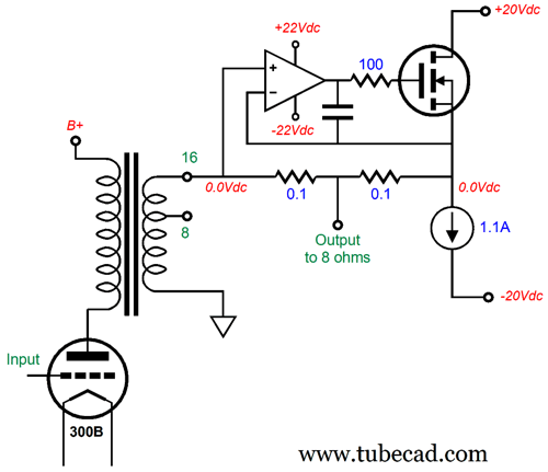
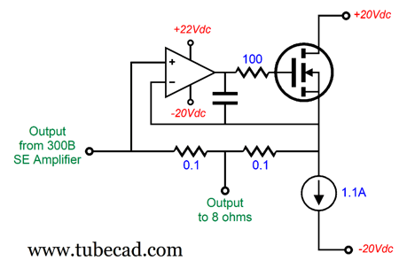
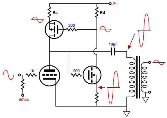
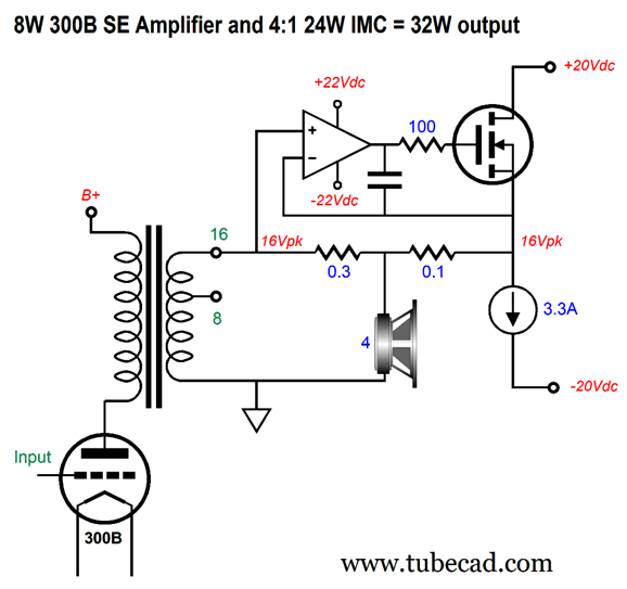
Here we see a high-voltage OpAmp driving a single power MOSFET that is loaded by a 1.1A constant-current source. The OpAmp must get a slightly higher bipolar power supply voltages than the MOSFET and constant-current source, due to the need of its output swinging a peak gate voltage about 4 to 5 volts higher than the peak 16V of output voltage swing. This assumes common vertical power MOSFETs; lateral MOSFET, in contrast, only require 1 to 2 volts higher gate voltages, so the op could run off the same bipolar power supply as the MOSFET and constant-current source.
The power MOSFET and the constant-current source are going to get hot, as each must dissipate 22W of heat at idle. The theoretical maximum efficiency of a constant-current source loaded single-ended output stage is 25%. In this example, with a total dissipation of 44W and 8W of output power, the efficiency is only 18%, which we derive from dividing 8W by 44W. In other words, the solid-state power buffer's efficiency will be lower than the 300B's, as the theoretical maximum efficiency of a transformer-coupled single-ended output stage is 50%. In other words, think big heatsinks. We could try to forgo the OpAmp and run the output MOSFET as a simple source follower.
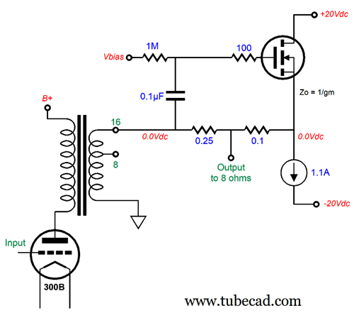
The 0.1µF coupling capacitor relays the signal put out by the 300B-based amplifier to the MOSFET's gate. Voltage Vbias must be found to ensure no DC offset at the output. The best practice is to use a DC servo.
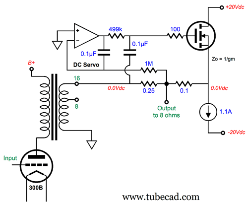
The OpAmp is working as DC servo, which does not provide any AC signal to the MOSFET's gate. Its only job is to prevent a DC offset at the source follower's output. Note the 0.25-ohm resistor. Without the OpAmp to control the MOSFET, the source follower's output impedance is equal to the inverse of the MOSFET's transconductance. This output impedance must be added to the left resistor's value to balance the current delivery by the 300B and the MOSFET. In SPICE simulations, however, the performance of this variation was poor. Okay how do get the secondary bipolar power supply rail voltages needed to power the OpAmp? We could simply add another smaller power supply transformer. Or, we could get sneaky and use two full-wave, voltage-doubler circuits to create four bipolar power supply rail voltages.
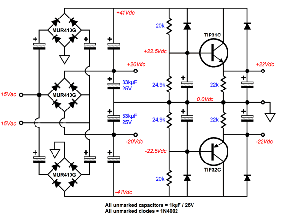
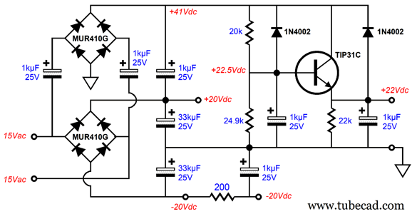
A 30Vac center-tapped power transformer secondary powers the entire IMC power supply. The 15Vac AC voltage rectifies up to about 20V after rectifier losses. The two voltage-doubler circuits create the +/-41Vdc bipolar power supply rails. We then employ two simple capacitance-multiplier circuits to create the +/-22Vdc bipolar power supply rail voltages. The two emitter-followers are robust and deliver a well-filtered DC to the OpAmps. As I look that the IMC circuit, I see that we might be able to forgo the -41Vdc power-supply rail, as the OpAmp's negative output voltage swing will never approach the -22Vdc rail voltage with a VMOS output device.
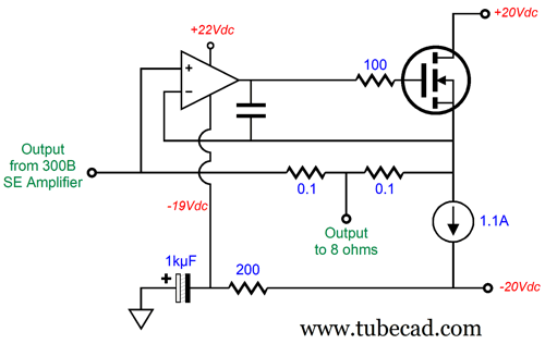
The OpAmp's negative power-supply pin could attach to the -20Vdc rail directly, but I would use an RC low-pass filter instead.
Here is the modified power supply circuit that only voltage doubles the positive rail voltage.
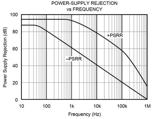
The low-pass RC filter made up from the 200-ohm resistor and the 1kµF capacitor provide some extra filtering of the OpAmp's negative power-supply-rail voltage, which is a good idea, as most OpAmp exhibit a much worse PSRR relative to their negative power-supply pin than to their positive power-supply pin.
Okay, now we move on to the interesting problem of 4-ohm loudspeakers. Problem, what problem? Let's start with the math behind delivering 16W into a 4-ohm load. The 8-ohm load's peak voltage swing of 16Vpk is reduced to 11.3Vpk and the peak current swing increases to 2.83Apk. Note that 16Vpk against 2Apk equals 32Wpk and 11.3Vpk against 2.828Apk equals 32Wpk. Average watts are equal to half the peak watts. Thus, the constant-current source will have to deliver 1.414A of current at full output; but since it is set to only 1.1A, expect problems. In other words, the IMC will clip on negative swings (the output MOSFET can always deliver positive current flow in excess of the constant-current source). The workaround is to increase the constant-current source idle current to 1.5A. But this creates a new problem: extra heat, as 1.5A against a 40V power-supply voltage differential equals 60W of heat, bringing the single-ended buffer's efficiency down to only 13.3% and making the heatsink extra hot. The next problem is that the IMC doubles the load impedance seen by the driving amplifier, which in this example with a 4-ohm loudspeaker will be 8 ohms. The 300B's output transformer cannot deliver 8W from its 16-ohm tap into an 8-ohm load. Not only is using a 4-ohm loudspeaker a problem with this design, it is also a problem with other wattage doubling techniques, such as running an SRPP output stage.
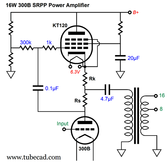
The 300B is configured in an SRPP topology with the power pentode (KT120). Contrary to audiophile opinion, the "PP" in SRPP does not stand for "single-ended," but for "push-pull." This is pure push-pull operation, as the two output tubes work in current anti-phase to each other: as the 300B conducts more, the KT120 conducts less; and vice versa. The current-sense resistor (Rs) functions as a poor man's phase splitter by creating an anti-phase signal to drive the pentode. (The cathode resistor Rk is there to bring down the KT120's transconductance to match that of the 300B.) Unlike a more conventional phase splitter, however, the current-sense resistor's value is dependent on the load impedance being driven. In the SRPP, one size does not fit all. Attaching an 8-ohm load to the 16-ohm tap (the result of using a 4-ohm loudspeaker in this example), will over drive the pentode, as too big a drive signal will be generated across the current-sense resistor. This also applies to faux single-ended topologies, such as the one shown in post 466, the "Steered Constant-Current Source amplifier." Patent pending, by the way: US10256776B1. (I recently reread my old post and was impressed by my analogy of a car that held a gas tank and gas-burning engine to drive the front wheels and a big battery and an electric motor to drive [steer] the real wheels' rotation, while claiming to have invented a car that doubled gas mileage.)
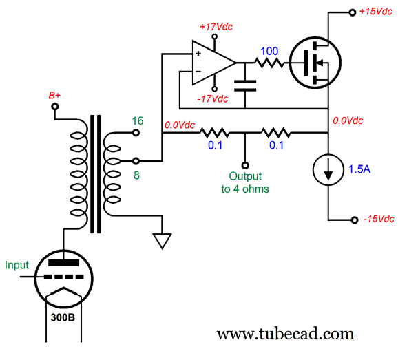
This circuit assumes and is optimized for a fixed load impedance, as it, too, suffers from a lazy phase splitter. (A well-designed push-pull amplifier's phase splitter should be load independent.) The simple workaround for these circuits is to use an output transformer with several load-impedance secondary taps. Returning to my truly single-ended alternative wattage-doubling circuit, the 4-ohm speaker workaround is to use the 8-ohm output tap on the secondary and to lower the bipolar power supply rail voltages and to increase the constant-current source idle current flow.
The 300B amplifier "thinks" it's powering an 8-ohm loudspeaker, as does the unity-gain power buffer. The 4-ohm loudspeaker receives 16W of power, 8W from the 300B amplifier and 8W from the power buffer.
How do we reduce the buffer's bipolar power supply voltages efficiently? We use a power transformer with multi-voltage taps.
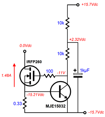
The center-tap is held constant throughout, but we would choose between a 30Vac differential and a 24Vac differential voltage to drive the bridge rectifier circuit. The power constant-current source can be made up with a power MOSFET and an NPN transistor.
The 0.33-ohm resistor sets the idle current flow through the N-MOSFET; for an 8-ohm loudspeaker, we would use a 0.43-ohm resistor. (I would place 0.1-ohm and 0.33-ohm resistors in series, with a switch to short out the 0.1-ohm resistor with 4-ohm loudspeakers.) By the way, we can use a power output transistor in place of the N-MOSFET as the output device.
Note that the OpAmp runs off the same bipolar power supply rail voltages as the rest of the power buffer does. If we wanted to increase the 300B amplifier's power output fourfold (32W), we could use the 16-ohm transformer secondary tap and an IMC with an impedance ratio of 4:1, but at the cost of huge heatsinks and lots of heat.
At idle, the IMC must dissipate 40V against 3.3A, which equals 132W. On the other hand, if we are willing to forgo the single-ended IMC and opt for a class-AB (or even class-D) IMC, the bulk of the heat production will come from the 300B amplifier.
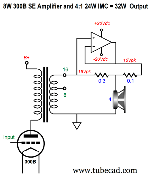
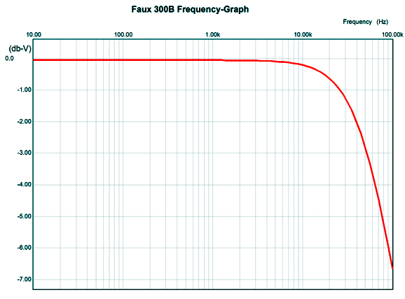
As far as the 300B is concerned, it is delivering 8W into the external load of 16 ohms. As far as the IMC is concerned, it is delivering 24W into the external load of 5.33 ohms. To drive an 8-ohm speaker, we use the 16-ohm tap and two 0.1-ohm IMC resistors, but we only get 16W of output. Note how this is much like a conventional solid-state power amplifier that delivers twice the power into a 4-ohm speaker than it does into an 8-ohm speaker. Okay, John, very sneaky as usual, but wouldn't that power doubling come at the expense of halving the sonic glory of the single-ended 300B power amplifier? I doubt that anything close to halving the sonic glory would occur. Why not? The unity-gain, power buffer gets its input signal from the 300B amplifier's output. In addition, I ran some SPICE simulations and I was quite pleased with what I saw. First, I created a faux 300B output signal by cascading five AC voltage sources, each set to a different sinewave frequency. Why? I wanted an exact amount of 2nd, 3rd, 4th, and 5th harmonic distortion at full output (16Vpk). In addition, I imposed an upper bandwidth limit of 52kHz, which is what I expect the typical 16W single-ended output transformer would deliver.
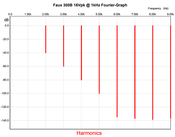
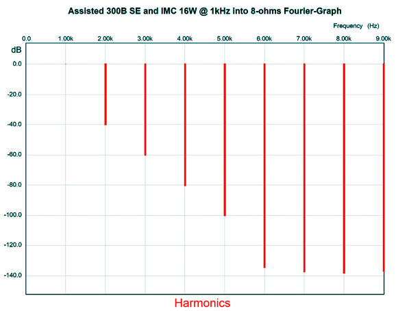
I then fed this input signal into the IMC circuit and beheld almost no diminution of sonic glory, as the output overlapped nearly perfectly with the input signal (i.e. the signal created by the faux 300B). First, here is the SPICE-generated Fourier graph for just the faux 300B output signal.
The reason it flatlines at about -140dB is that the 52kHz low-pass filter introduces some phase shift; without the filter, the flatline would appear at around -180dB. Now, let's compare it to the what the loudspeaker sees across the leads due to the contribution of the IMC. (The OpAmp SPICE model was of a Linear Tech OpAmp and the MOSFET model was of the IRFP260.)
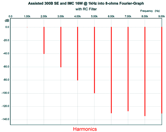
Not that much difference, is there? Next, I decided to see what the version with the RC low-pass filter on the OpAmp's negative power-supply rail would produce.
Only slightly worse. Okay, here is one last variation. Rather than use a high-voltage OpAmp, why not use a high-voltage vacuum tube, such as the 12DW7, which holds dissimilar triodes, a 12AX7 and a 12AU7 triodes.
Configured as a grounded-grid amplifier, the 12AX7's cathode is the input, and its grid is its negative feedback input. If the MOSFET source follower's output does not mirror the 300B-based amplifier's output, the 12AX7 will react to the difference, forcing the MOSFET back in line through the 12AU&-based cathode follower's output. In other words, the OpAmp's function remains—it's just been replaced by a tube. Of course, the 12AX7's open-loop gain is the tiniest fraction of the OpAmp's; nonetheless, the MOSFET's transconductance will effectively be multiplied by the 12AX7 gain, which will approach 1:100 (40dB). I have yet to create a SPICE circuit of this design to evaluate it. (I have more ideas than free time, alas. I once knew a drug dealer who told me that if he had a staff of employees, he could rule the drug world. Well, if I had group of capable EE graduate students, I could rule the…)
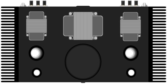
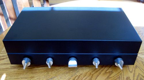
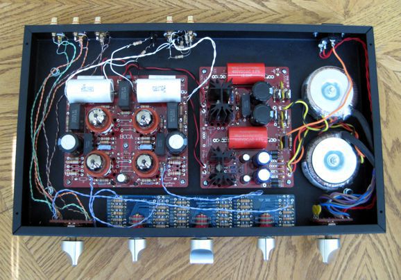
Latest Project The differential-input line-stage amplifier worked fantastically, and then slowly declined in sonic glory. Finding the second problem took some detective work, but I found it: a faulty resistor that had been damaged when the attenuator failed to provide a solid path to ground. With the attenuator fixed and the flaky resistor replaced, the line-stage amplifier sang. The chief difference I heard was a better stereo image, being both more focused and wider.
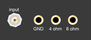
The leftmost knob is the input selector, which chooses from three input signal sources—and, most importantly, their grounds. The center three knobs attach to an Attn-1 stepped attenuator. The rightmost knob is the power switch that offers a staggered turn-on, so the heaters get hot before the B+ voltage comes on. On the back, two sets of output RCA jacks are provided, so powered subwoofers can be used directly.
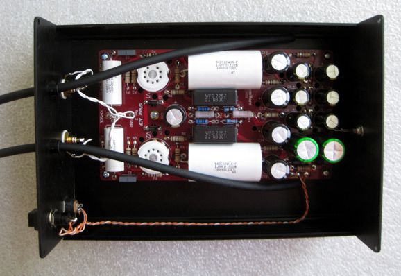
This success led to my modifying a 12Vac ACF to function differentially at its input(s).
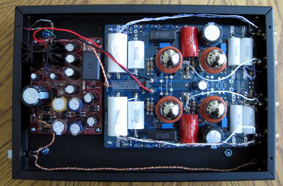
This is what I started with, but I had to add two more input coupling capacitors to achieve the desired differential inputs. The unity-gain buffer relies on the volume control within the DAC signal source to adjust the volume. I liked the results so much, I gave the project to a good friend. My last project was to try an Unbalancer-2, powered by a 12Vac PS, which creates a relatively high-voltage B+ voltage and a regulated 12Vdc heater power supply—from a 12Vac wallwart transformer. The tubes are 6DJ8s.
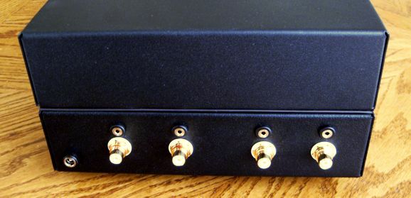
The input and output RCA jacks each hold an accompanying 2.5mm mono headphone jack. Why? To offer high-voltage polarization of the interconnects.
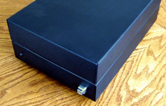
The front panel holds only a power switch and indicator LED.
Like the other two projects, this differential-input circuit delivers the same improved stereo image, along with some welcome tube warmth, which undoes some of the chilly sound leaving the solid-state DAC. Note that all three projects enclosed the tubes in a sealed box. Why? I did some shootouts with exposed tubes and covered tubes. What I found, much as I expected, the exposed tubes add some vibrato to sound, as they function as tiny microphones. True, this sonic overlay was only obvious when playing loudly and with bass-filled music. But isn't the definition of an audiophile that of a man who listens to bass-heavy music too loudly? Sealed away, the sound becomes more focused, less ripe. Since, the top half of the enclosure is only held in place by long strips of magnetic tape, it is easy to enough to play the units topless.
Music Recommendation: Wicked Game
Interestingly, half the singers change the line, No, I don't wanna fall in love... to No, I wanna fall in love.... (Some even seem to be singing, Oh, I wanna fall in love...) I believe the altered line is the result of different interpretations of what the song is about. Most think it is a song about unrequited love or about his resistance to falling in love with a woman fully deserving to be loved, finding it similar to the 10cc song, I'm Not in Love. The inspiration for the Isaak song, however, was his getting a phone call from a strange woman who informed Isaak that she was coming over to talk to him, where "talk" meant have sex. She proclaimed that she would "talk" to him so long and so hard that he could no longer stand. Being (in other words, identifying as), at least at the time, a typical CIS-gender man, a once woefully customary and prevalent mental affliction, a disorder which today we happily have largely transcended and renounced, with complete scientific consensus and the entirety of enlightened public opinion, he said, "Sure, come on over." As he hung up the phone, however, the perversity of the situation hit him, and the song flashed into his mind and he set about writing it down. When she arrived, he told her to forget that wicked nonsense and to listen to the great song he just wrote. Another difference in the singing of the song is that half the singers leave out the final line:
Once again, this elision, no doubt, is the result of differing interpretations of what the song is about. My search delivered many fine covers of Isaak's song. I liked those by Abraham Alexander, Carmen Gomes, Daisy Gray, Gemma Hayes, Jessie Villa, Karen Mok, London Grammar, Midland, Stone Sour. The standout, however, was that by the South African singer, Annaca (aka, Annaca Espach).
She can sing. From her Patreon page we learn:
I am now supporting her at Patreon. Can I give any higher recommendation?
//JRB
Very few can imagine just how much hard work is required to make one of my posts. This post, for example holds 5,500 words and more schematics than I want to count. What isn't seen, however, is the math, research, and SPICE simulations required for each post. If you have any sort of inkling or intuition of what is involved, both in time and effort, please think about supporting me at Patreon.
User Guides for GlassWare Software
For those of you who still have old computers running Windows XP (32-bit) or any other Windows 32-bit OS, I have setup the download availability of my old old standards: Tube CAD, SE Amp CAD, and Audio Gadgets. The downloads are at the GlassWare-Yahoo store and the price is only $9.95 for each program. http://glass-ware.stores.yahoo.net/adsoffromgla.html So many have asked that I had to do it. WARNING: THESE THREE PROGRAMS WILL NOT RUN UNDER VISTA 64-Bit or WINDOWS 7 & 8 & 10 or any other 64-bit OS. I do plan on remaking all of these programs into 64-bit versions, but it will be a huge ordeal, as programming requires vast chunks of noise-free time, something very rare with children running about. Ideally, I would love to come out with versions that run on iPads and Android-OS tablets.
//JRB |
|
I know that some readers wish to avoid Patreon, so here is a PayPal button instead. Thanks. John Broskie
John Gives
Special Thanks to the Special 80 To all my patrons, all 80 of them, thank you all again. I want to especially thank
I am truly stunned and appreciative of their support. In addition I want to thank the following patrons:
All of your support makes a big difference. I would love to arrive at the point where creating my posts was my top priority of the day, not something that I have to steal time from other obligations to do. The more support I get, the higher up these posts move up in deserving attention.
Only $12.95 TCJ My-Stock DB
Version 2 Improvements *User definable Download for www.glass-ware.com |
||


| www.tubecad.com Copyright © 1999-2022 GlassWare All Rights Reserved |