| John Broskie's Guide to Tube Circuit Analysis & Design |
22 September 2009
Most classical music fans have heard of the curse of the ninth. The curse, which started with Beethoven and ended with Shostakovich, would claim the life of any composer who wrote a ninth symphony, leaving them dead soon after its completion. Gustav Mahler, in a sneaky attempt to cheat death, titled his actual ninth symphony Das Lied von der Erde, but nonetheless died soon after writing his official ninth symphony. Well, I am greatly relieved that there is no curse on writing about the same circuit topology nine times. For it there were, I would be in trouble, as I have written on the famous SRPP circuit at least ten times so far.
At least that is as many instances that I could easily find via Google. Interestingly enough, prior to performing the search, I would have guessed that five was the total, as I have somewhat fallen prey to partially believing the epitaph so many have stuck on me: He’s the anti-SRPP guy. In truth, I am not anti any topology, but I am very much anti-nescience in general and anti-unreasoning, as it is applied to electronic circuits, in particular—in a nutshell, if a circuit can be designed, it can be understood and explained. (Have you ever noticed that those claiming complete understanding of tube electronics while also claiming that this deep understanding is inexplicable are often the same fellows building and selling high-end tube audio gear?) And I am very much anti-absolute-circuit, opposing any claim of universal perfection. It’s not the perfect that troubles me; it’s the universal, the implicit claim of perfection independent of (and unrelated to) anything else. The circuit that worked beautifully as phono pre-preamplifier is not likely to work as well as a subwoofer amplifier, for example.
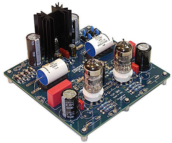
The irony here is that I was once a huge SRPP zealot back in the early 1980s, using it as my key topology and promoting it to anyone who would listen—before I understood how the circuit worked. Today I am much more circumspect, heedful of its assets and liabilities. When I have felt that it was the best circuit for a particular application, I have used it for that application. In other words, I am not anti-SRPP by any means. In fact, I have recently felt the soft gnaw of nostalgia as I recall my college days, when I had built a 6DJ8-based SRPP headphone amplifier for my altogether wonderful Sennheiser HD-414 headphones. Unlike the new HD-414 remake, the original headphones boasted a 2k impedance, which required only a 6µF coupling capacitor for bandwidth down to 20Hz. (I used my HD-414s with my 200lbs, coffin-sized subwoofer that crossover at 80Hz, so I only needed a 1µF capacitor; an OTL with 1µF coupling capacitor!) This simple headphone amplifier used two 6DJ8/6922 tubes and a hefty 200V power supply and sounded amazingly sweet. Simple—when you can get away with it—is great. Thus, with my heart filled with warm, fuzzy feelings, I decided to lay out a new All-in-One PCB that honored the SRPP circuit, but with a plus.
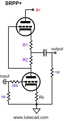
The plus takes the form of a topological variation I came up with over a decade ago and which appears in the May 2000 issue of the Tube CAD Journal.
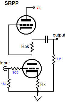
Before explaining the SRPP+ topology, let’s do a quick review of how an SRPP circuit works.
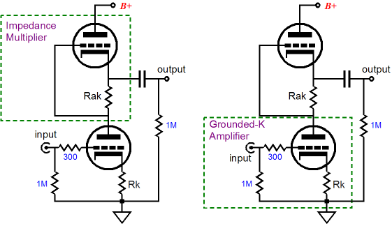
The Secret Behind the SRPP The answer is that the SRPP is actually two elemental circuits, not one. It is a compound circuit that holds a simple grounded-cathode amplifier that provides voltage gain and an impedance-multiplier that is neither a unity-gain buffer nor voltage amplifier. Two sub-circuits? The bottom triode is configured as a grounded-cathode amplifier that sees its plate loaded by a magnified load impedance provided by the top triode, which is configured as an impedance-multiplier. What is an impedance-multiplier? An impedance-multiplier is a circuit that effectively inflates the impedance presented by the load. An impedance doubler, as an example, doubles the effective impedance of the external load; for example, 300 ohms will be reflected as being 600 ohms. Thus, a 1mA current flow into the impedance-multiplier will not produce the 0.3V voltage drop across the 300-ohm load resistor, but instead 0.6V will develop across the resistor. So as far as the bottom tube in the SRPP is concerned, the 300-ohm load is now a 600-ohm load, which means that greater gain is now realizable by the grounded-cathode amplifier.
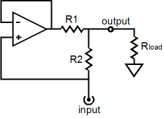
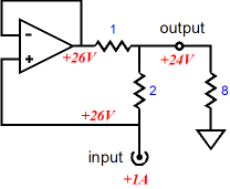
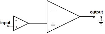
We will tear away the impedance-multiplier portion of the SRPP, so that we can examine it in isolation, but first let’s examine a conceptually pure impedance-multiplier. The following may look like a solid-state OpAmp circuit, but think of it as an idealized OpAmp, whose underlining technology is unspecified—possibly alien and unknown on our planet—but which adheres to the concept of a perfect OpAmp: infinite open-loop gain, infinitely low output impedance, and infinitely wide frequency bandwidth, a true voltage amplifier, one capable of delivering infinite current into a load.
Resistors R1 and R2 set the impedance multiplication. If they equal one another, the multiplication will equal 2, doubling the load impedance. Using 1 ohm for R1 and R2 and an 8-ohm load, let’s examine what happens when 1A of positive-going current is applied to the impedance-multiplier’s input.
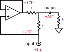
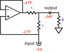
Normally, 1A against 8 ohms equals a voltage drop of 8Vdc, but in our circuit the 8-ohm load sees 16Vdc developed across its leads. Where did the extra 1A of current come from? The super OpAmp must keep both its input pins, the inverting and non-inverting pins, at the exact same voltage. Which in this example is only possible when the OpAmp’s output voltage equals the input voltage presented to the impedance-multiplier’s input? Wait a minute, didn’t we just apply a 1A current to the input, not a fixed DC voltage? Yes indeed, but as soon as any current flows into the impedance-multiplier’s input, a voltage develops across the load resistor and resistor R2, which will then also appear at the OpAmp’s output. Any in-phase voltage on the OpAmp’s output means that the OpAmp is also delivering current into the load. As we can see in this example, the OpAmp is slavishly matching the 1A of current into the load, thereby doubling the current into the load. (In other words, we could just as easily think of this the impedance-multiplier circuit as a current-multiplier circuit.) If the input current pulled down, rather than pushed up, the load would still see a 16V voltage drop, but with the current flowing in the opposite direction.
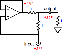
What would happen if we applied a fixed voltage to the impedance-multiplier’s input, instead of a fixed current flow? As far as the load resistor is concerned, not much would be different.
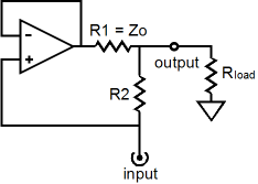
Once again, this circuit functions as an impedance multiplier, so the 17Vdc fixed voltage must also imply a current flow of 1A from the external voltage source. Well, why wasn’t 16Vdc applied, rather than 17Vdc; isn’t twice 8 ohms equal to 16 ohms? The impedance-multiplier input impedance does not exactly equal twice load impedance, as resistor R2’s resistance is in series with the doubled load impedance. Expressed as a formula: Zin = R2 + Rload(R1 + R2) / R1 When R1 = R2, Zin = R2 + 2Rload While on the subject of formulas, we might as well fill in the blanks, for example the output impedance and the circuit’s “gain,” as seen by the load. Assuming a current source as the signal source and assuming R1 equals R2: Zo = Infinity Voltage Gain = Current x 2Rload Assuming a low-output-impedance voltage source as the signal source and assuming R1 equals R2: Zo = R1 || R2 Voltage Gain = Vin x 2Rload / (R2 + 2Rload) Yes indeed, there is a voltage loss when the impedance-multiplier’s input is a fixed voltage, as resistor R2 and twice the load impedance define a two-resistor voltage divider. In fact there is also a voltage loss of sorts when the input signal derives from a current source, as the impedance-multiplier’s input impedance is greater than the just twice the load impedance, so the voltage drop across R2 represents a loss of voltage. The best course to travel is the one that avoids thinking about “gain,” as voltage gain is not the impedance-multiplier function, no more than it is a resistor’s. The interesting result is the output impedance as seen by the load. With a current source as a signal source, the output impedance approaches infinity and the impedance-multiplier resembles a current-output amplifier, like Nelson Pass’s First Watt amplifier. With the voltage source as a signal source, the output impedance is as low as resistors R1 and R2 in parallel and the impedance-multiplier resembles a tube amplifier, with its low damping factor. In other words, if you are only familiar with voltage power amplifiers, the impedance-multiplier circuit must seem very strange indeed. Sometimes it acts sort of like a power amplifier; at other times, a unity-gain buffer of sorts, but not quite. Furthermore, a power amplifier’s output impedance is independent of the signal source’s output impedance, whereas the impedance-multiplier circuit’s output is entirely dependent on the impedance presented to its input. Put another way, stop thinking power amplifier; think impedance-multiplier circuit. Anticipate possible fault conditions and incorporate safety features. For example, if the impedance-multiplier circuit is fed from a current source, rather than a voltage source, an open circuit at the impedance-multiplier circuit’s output spells danger, as any amount of current against infinity implies infinite voltage swing. (See Blog 98 for more information on fault conditions with a current-output amplifier.)
The obvious answer is that the OpAmp will have to deliver more current into the load than the input signal source; but how much more?
In the example above, resistor R2 is twice R1’s value, so the current flow through R2 must be half that through R1, as both resistors see the same voltage differential; thus, the current ratio is equal to R2/R1. But what is the impedance multiplication in this example? Z = Rload(R1 + R2) / R1 This allows us to conclude that the input impedance presented by the impedance-multiplier circuit is: Zin = R2 + Rload(R1 + R2) / R1 While we are at it, the “gain” and Zo, assuming a current source as the signal source are: Voltage Gain = Current x Rload(R1 + R2) / R1 Zo = Infinity Assuming a low-output-impedance voltage source as the signal source: Voltage Gain = Vin x [Rload(R1 + R2) / R1] / [R2 + Rload(R1 + R2) / R1] Zo = R1 || R2 This raises an interesting question, What happens if R1 equals zero ohms? The impedance multiplication ratio will equal infinity and the impedance-multiplier circuit must deliver infinitely more power into the load than the signal source. This is impossible in reality, of course. In the real world, the impedance-multiplier circuit will always contain an implicit R1 resistance in the form of the OpAmp’s output impedance, albeit that this impedance can be amazingly low with modern, high-powered, solid-state power amplifiers.
Okay, now switch mental gears and think back to April of 2008, in Blog 140, wherein I describe the New Hybrid SE OTL Design in audioXpress Magazine.
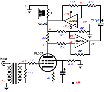
AJ van Doorn’s hybrid power amplifier also uses a high-powered solid-state power amplifier and low-powered SE tube to provide voltage gain and a wee amount of power into the load. With a few adjustments and much editing, we end up with something like this.
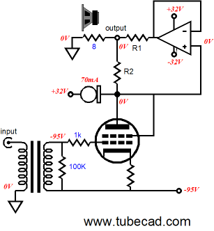
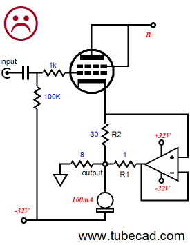
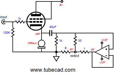
The amplifier shown above could use a high-current triode, such as the 6C33, or pentode, such as the 6LF6. The tube would work in single-ended, class-A mode, with the constant-current source loading its plate. Resistors R1 and R2 would have to be adjusted to provide the optimal impedance multiplication. And the input transformer would have to offer a large step-up ratio. Of course, the input transformer could be eliminated, along with the negative power supply, if we used a coupling capacitor to bridge the tube amplifier to the impedance-multiplier circuit, but then the output tube would demand a huge input voltage swing from the line-stage amplifier, something most tubes do plentifully well. The output impedance must be staggeringly high, even with a triode in place of a pentode. By turning this circuit on its head, we can use a cathode follower to lower the output impedance.
Why the unhappy face? The above circuit will suffer from DC offset woes, as the output and the cathode cannot be both a zero volts, while any current flows through the tube. One possible workaround is to add a DC servo loop that would steer the power OpAmp’s output to a slightly negative voltage that would then offset the positive tug from the output tube, resulting in 0V at the loudspeaker connection.
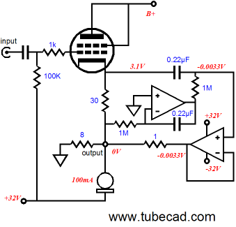
The big test for any possible solution is will it protect the loudspeaker when the tube is cold and not yet conducting or jiggled in its socket, breaking its contact with the rest of the circuit? In this example, I am inclined to think everything will work out. In fact, the only problem I see is having to create a separate bipolar power supply for the DC-servo OpAmp, as few 8-pin IC OpAmps can handle 64V of power supply voltage. So, is it possible to forgo the extra OpAmp?
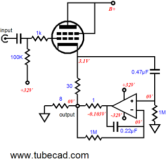
The above circuit uses the power OpAmp itself as its own DC servo and the tube’s quasi constant-current source. One aspect of this and the previous variation that may escape notice is how the tube’s idle current is not fixed at 100mA, although it must be more obvious with the this last variation. The -32V bias voltage and the 30-ohm cathode resistor set the idle current for the output tube. This might prove a big liability with some tubes; high-gm tubes are often quite squirrelly in terms of idle current. The next variation reintroduces the constant-current source and it will force the output tube to conduct a specified idle current, even with variations in wall voltage or tube ageing.
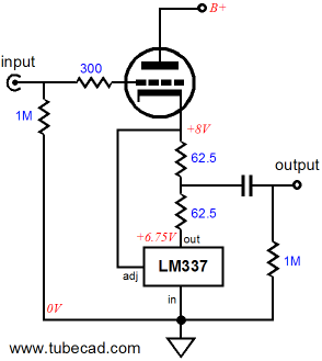
Ok, let us step back a bit and think small. Few have the money, the expertise, and the guts to build a big power amplifier. How could we easily use an impedance-multiplier circuit and a single tube to build a nice unity-gain line buffer? The following circuit uses an adjustable negative three-pin voltage regulator reconfigured as an impedance-multiplier circuit. The LM337 strives to keep a fixed voltage differential of -1.25V across its adjustment pin and its output pin. If not external load attached to the two 62.5-ohm resistors, this fixed voltage across 125-ohm of resistance would define a constant-current source of 10mA. In other words, the tube must conduct 10mA of current and only 10mA at idle.
With a load impedance and an input signal, however, the load will divert current and the tube’s current conduction can swing from 0A to 20mA, as can the LM3337. The load sees the delta in conduction between tube and LM337. Thus, at idle, no current flow into the load (ignore the coupling capacitor). But as the tube’s cathode swings up and the tube conducts more, the LM337 conducts equally less, so the external load sees twice the current swing that the tube or LM337 sees; in this case -20mA to +20mA. In other words, we have a seemingly single-ended circuit (like the SRPP) that operates in a push-pull fashion. As far as the tube is concerned, the external load impedance has been doubled (plus 62.5 ohms) and its distortion characteristic is very single-ended. As far as the LM337 is concerned, any change in the voltage differential must be countered by varying current and the LM337 doesn’t know or care where that varying current ends up as long as the 1.25V voltage differential obtains. In my next post, I will explain how the above circuit works in great detail. By the way, expect this circuit to be invented in the near future (and patented) by one of the big tube-gear companies. Of course, no mention will ever be made of me or the Tube CAD Journal and the name given to the circuit will be something like the Super-Lin Follower™. Maybe I should preemptively strike and name it the “Inverted SRPP” or something more whimsical, say the “Somersault Circuit.” (My four-year old daughter would love it, as she asked me the other day, “Daddy, what’s the etymology of somersault?” That’s my daughter!)
Power-Booster Amplifiers
Now let’s switch gears again and think back to the topic of power-booster amplifiers, covered in Blogs 157, 155, 154, and 153. The idea behind the power-booster amplifiers is that a small, flea-power amplifier and a huge, heavy, power-booster amplifier are wed and the result is the ability to greatly magnify the wimpy amplifier’s output into hundreds of watts. The commercial example was the Musical Fidelity 550K power-booster, which presented a 50-ohm load to the small power amplifier. I have no idea what the 550K schematic looks like, but I am sure that it does not represent a true impedance-multiplier circuit. This is not a failing, just an observation. Now imagine a big impedance-multiplier circuit capable of delivering 500 watts into a loudspeaker and imagine a tube OTL power amplifier capable of delivering 1Apk with 100Vpk voltage swings. Such an OTL would require a 100-ohm load, which the impedance-multiplier circuit could create out of an 8-ohm load. In other words, the tube amplifier would deliver 1A and the solid-state impedance-multiplier circuit would provide 11A into the 8-ohm load. This could prove quite interesting, as 12A equals 576W into 8-ohm loads. Or imagine a loudspeaker that held a high-efficiency tweeter and midrange drivers, say 96dB @2.8V, and a low-efficiency, 2-ohm, 10 inch, car woofer (or four smaller 8-ohm woofers in parallel) in an acoustic suspension enclosure, but with deep, deep bass extension. Such a speaker could never just be hooked up to a conventional power amplifier, as a 2-ohm load would provoke gross distortion from most amplifiers. But if we added an impedance-multiplier circuit to only the woofer, the woofer could effectively see a fourfold increase in signal current, while still presenting an 8-ohm load to the external power amplifier, which would bring it efficiency up to the rest of the system. Might be just the answer to many a tube-loving audiophile's dreams; a small speaker with thundering bass and high efficiency. True, such a speaker would need to be plugged into a wall socket, but that might be a feature, as many would imagine that it was an electrostatic design.
SRPP All-in-One PCBs
Time to Stop
//JRB |
E-mail from GlassWare Customers
High-quality, double-sided, extra thick, 2-oz traces, plated-through holes, dual sets of resistor pads and pads for two coupling capacitors. Stereo and mono, octal and 9-pin printed circuit boards available.  Aikido PCBs for as little as $24 http://glass-ware.stores.yahoo.net/
Support the Tube CAD Journal & get an extremely powerful push-pull tube-amplifier simulator for TCJ Push-Pull Calculator
TCJ PPC Version 2 Improvements Rebuilt simulation engine *User definable
Download or CD ROM For more information, please visit our Web site : To purchase, please visit our Yahoo Store:
|
|||


| www.tubecad.com Copyright © 1999-2009 GlassWare All Rights Reserved |