| John Broskie's Guide to Tube Circuit Analysis & Design |
09 January 2009
Back to Power Boosters Another lofty ideal would be to have the minuscule tube power amplifier work in tandem with a burly solid-state powerhouse of an amplifier, like Hylas and Hercules.
Or if Ancient Greek myths are not your bag, how about the old Quad current-dumping power amplifier that used a small, high-quality class-A amplifier in parallel with a big, dirty, powerful, class-B power amplifier—the small clean amplifier erasing the big amplifier’s mistakes, while the big amplifier provides 98% of the current needed.
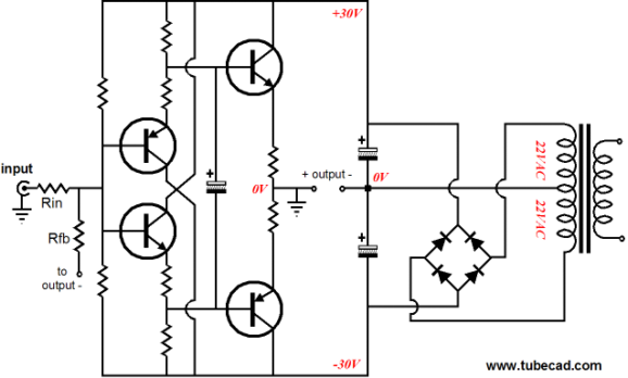
Now this sounds like a great idea (and here comes the “but”), but it is not easy to implement, as the refined small power amplifier must somehow control the big clunky power amplifier’s output; otherwise, like a small boy in an arm wrestling match with a Mr. Universe winner, the big amplifier will crush the little amplifier’s countering exertions. One solution is to enclose the bigger amplifier’s input and output within the feedback loop of the smaller power amplifier, as shown below.
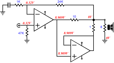
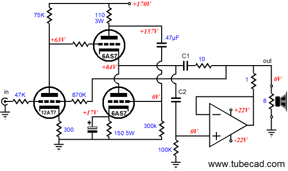
If this schematic looks familiar, it’s because it appeared in blog number 142. Since I already covered this topology then, I will only briefly recap now. The top amplifier is the small perfect amplifier and it sees a 10-ohm series resistor at its output; the bottom amplifier is the big brute of an amplifier that sees a 1-ohm resistor before attaching to the external load impedance. With the total current delivery of 1A into the loudspeaker, the top power amplifier delivers 90.9mA into the load, while the bottom power amplifier delivers the remaining 909mA. Also taken from blog 142 is the following hybrid configuration, wherein the tube-based OTL amplifier works in parallel, albeit a skewed parallel, with a big solid-state power amplifier.
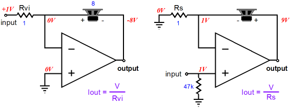
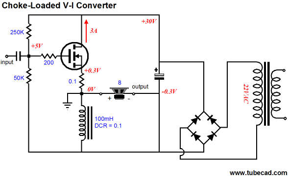
Another possibility might be to make the big power booster amplifier, not a voltage amplifier, but a current-output amplifier, like the Pass First Watt amplifier. In other words, design the booster amplifier to convert an input voltage into an output current. Below are the two basic V-I converter topologies.
So, where a voltage amplifier provides a fixed input-output voltage ratio, the voltage-to-current amplifier establishes a fixed voltage-to-capacitor ratio; and where a voltage amplifier presents an extremely-low output impedance, the voltage-to-current amplifier offers a supremely-high output impedance. The only real problem with this solution is designing an effective and safe voltage-to-current converter/amplifier, as it is not an easy task. Remember that when faced with an input voltage but no load resistance, the voltage-to-current converter should swing infinitely; and that keeping the converter’s output centered at 0V, with no input signal, can be quite a task in itself. By the way, the lowly choke can provide an easy workaround to the output-centering problem. The following schematic shows a simple voltage-to-current converter amplifier that uses a single power MOSFET. The MOSFET’s transconductance performs the voltage-to-current conversion for us, as the MOSFET’s current conduction will vary in the face of variations in its gate-to-source voltage. The loudspeaker then develops a voltage across its lead equal to its resistance against the change in current conduction; thus, an input signal of 1Vpk and a MOSFET with a gm of 3A/voltage and a loudspeaker with an 8-ohm impedance will develop 24Vpk swings across the loudspeaker, which equals 36W.
As this topology is so wrong looking, there is much to cover here. First, this converter is not a unity gain buffer, as it provides voltage gain and its ultra-high output impedance must surely disqualify it from holding the “buffer” title. Second, while this converter does not use an AC feedback loop, it does use a DC feedback loop to set the idle current. Third, this circuit must be run in strict class-A, as its mode of operation is purely single-ended. In other words, the idle current equals the maximum symmetrical current swing into the loudspeaker. Fourth, the 300mV DC offset might be a deal breaker for some loudspeakers, but not all speakers, as 300mV only equals 11mW of dissipation with an 8-ohm load. In addition, most midrange and all tweeter drivers will never see the DC offset because of their capacitor-coupled crossovers. The workaround, nonetheless, is to use either a lighter idle current or a lower DCR choke. An additional workaround would be to forgo the single-ended feature and build a push-pull version that used a center-tap choke instead, which would null the DC and increase the potential output power by fourfold, but would require a balanced input signal. Before I lose the end of my thread of thought here, let us return to the big picture idea of using a voltage amplifier in parallel with a voltage-to-current converter amplifier.
Now it is time to pause and review. Common to all of these attempts at designing a useful power-booster amplifier is that both the small and the big power amplifier/converters share identical maximum output voltage swings. This limitation is not a big deal with the OTL-based power-booster amplifier configuration, as OTLs can easily swing voltage, but not current. The 2A3-based single-ended amplifier, on the other hand, is not so lucky, as it is both voltage- and current-limited. And most small sweet solid-state amplifiers would most certainly be voltage-limited. To be universal, a power-booster amplifier that worked in parallel with all existing small amplifiers must find a way to work within the small amplifier’s output voltage limitations.
Diamond Buffer Topology
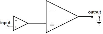
This famous four-transistor buffer topology has many adherents and a long history; see the datasheet for the LH0002, which came out in the late 70s. Precisely because it is so simple, because it is so easy to understand, it is venerated by many solder slingers. (It is in many ways the solid-state equivalent of the SRPP tube circuit.) Well, now it’s time to put on our mind-stretching caps. In my last two blog entries, I showed several voltage amplifier topologies that looked like unity-gain buffers, such as my Sagaris Amplifier. For example, the following schematic shows an amplifier, not a buffer.
Now, what would happen if we grounded the output of a diamond buffer, such as the famous BUF634, while we left the dual-rail power supply floating?
The diamond remains, but the circuit now functions as an inverting voltage amplifier. Why would one want to tamper with perfection? Well, let’s say that you want to add a power booster to your iPod or Zune’s output, but you need some voltage gain to drive your esoteric headphones. The stock BUF634 can only deliver unity gain, but the above amplifier could provide the needed +6dB of gain (x2) that you seek. The output would still be low, but not as low as the buffer—which may not matter that much in this application.
//JRB
|
Kit User Guide PDFs
E-mail from GlassWare Customers
High-quality, double-sided, extra thick, 2-oz traces, plated-through holes, dual sets of resistor pads and pads for two coupling capacitors. Stereo and mono, octal and 9-pin printed circuit boards available.  Aikido PCBs for as little as $24 http://glass-ware.stores.yahoo.net/
Support the Tube CAD Journal & get an extremely powerful push-pull tube-amplifier simulator for TCJ Push-Pull Calculator
TCJ PPC Version 2 Improvements Rebuilt simulation engine *User definable
Download or CD ROM For more information, please visit our Web site : To purchase, please visit our Yahoo Store:
|
|||


| www.tubecad.com Copyright © 1999-2009 GlassWare All Rights Reserved |