| John Broskie's Guide to Tube Circuit Analysis & Design |
08 March 2022 Post 554
I got Nelson Pass's US Patent, 5,343,166, Efficient High Fidelity Audio Power Amplifier, utterly wrong in post 521. At the time, I was obsessed with class-G and class-H amplifiers and saw what I wanted to see—not what was there—in spite of scanning the patent's text. Well, "scan" is an interesting word, as it comprises its own antonym, as it means both to examine systematically and to glance briefly. I performed the latter verb, not the former. I was seeking prior art for my de-glitching technique for class-G amplifier output stages, wherein an extra resistor provides a current path between top and bottom class-G transistors (or MOSFETs) which prevents these devices from ever completely cutting off, thereby preventing oscillations due to transistor lead inductance.
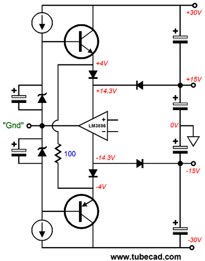
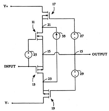
The 100-ohm resistor prevents the two transistors from cutting off. I thought I had found the prior art in Pass's patent, even though the patent describes a cascode output stage, not a class-G output stage. When I saw the patent's first schematic, I failed to note the constant-current source's symbol arrow direction.
Perhaps I assumed that the arrow followed actual current from negative to positive, rather than "conventional" current flow that has current flowing from positive to negative. The symbol's arrow follows the conventional flow of current, which means that the top and bottom cascode transistors (or MOSFETs) can and will cut off completely. The first word in his patent's title is "Efficient." What Nelson sought was an extra rich idle current for the center transistors or MOSFETs, which would linearize their output, but not incur the huge increase in total output-stage dissipation. By limiting the center output device's voltage window to a small portion of the total rail-to-rail power-supply voltage, and by using a floating power supply and constant-current source, we can run these center output devices under high idle current, without having to share that high idle current flow with the cascode output devices, as these over and under devices need only deliver the missing portion of current flow that the floating power supply cannot deliver. The result is high-quality output but without the costs of pure class-A amplification, such as massive heatsinks, power transformers, and many parallel output devices. Let's start with a conventional cascode output stage.
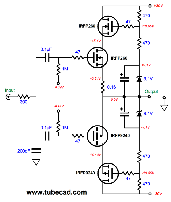
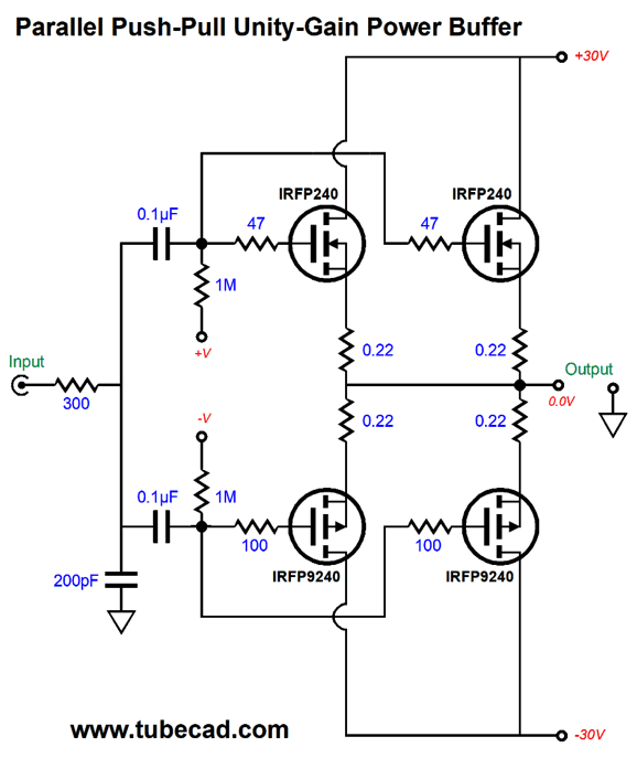
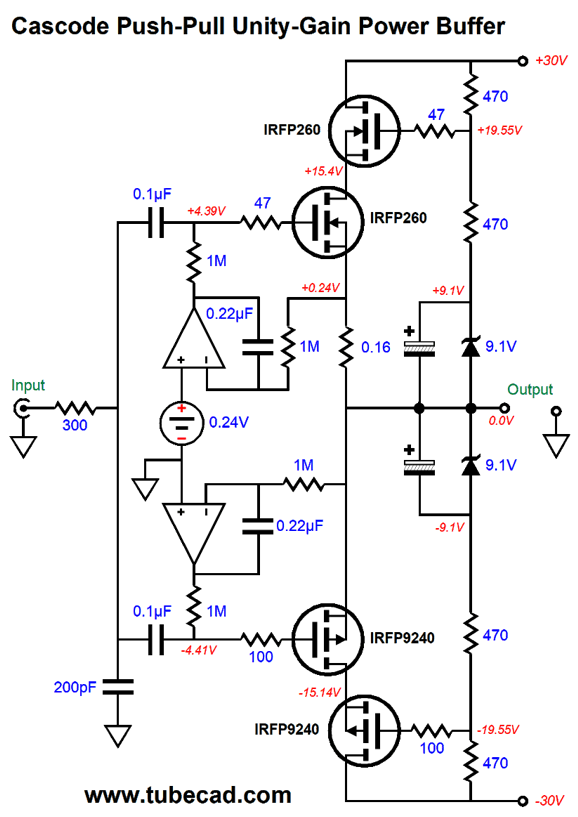
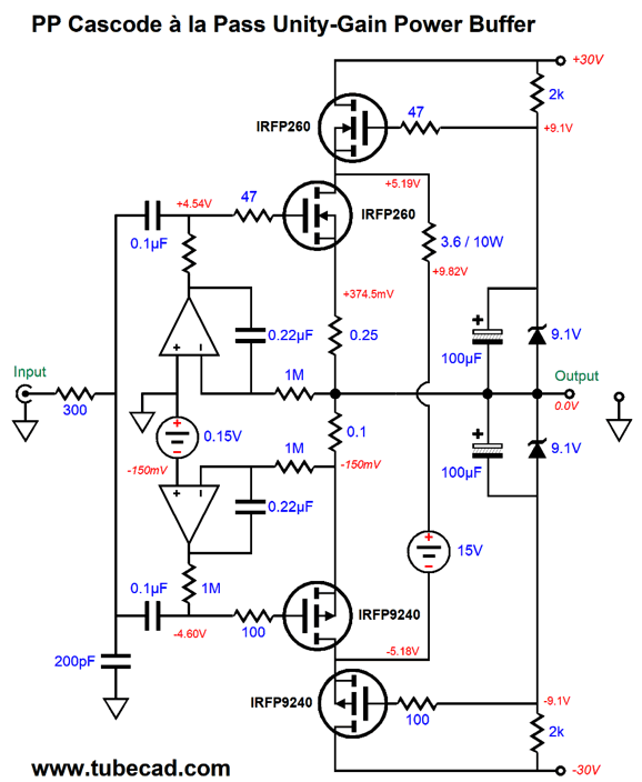
This is a unity-gain power buffer that can deliver 36W of class-A power output into an 8-ohm load. The price in heat that we must pay is 90W of dissipation at idle, which implies an efficiency of 30W/90W or 33%, 17% below the theoretical maximum efficiency of 50%. All the output devices dissipate nearly the same amount of heat, 22.5W. At the same time, the input capacitance is half of what it would be with the conventional four-device parallel output stage.
The halving of input capacitance is important with power MOSFETs, such as the IRFP260, whose input capacitance is a heavy 5.2nF (5,200 pF). In contrast, a 6AS7 triode's grid-to-plate capacitance is a mere 12pF. The cascode arrangement, however, will present twice the output impedance of the parallel arrangement of source followers. Parallel arrangement also requires that matched output devices be used to prevent current hogging. (Lateral MOSFETs, however, exhibit a negative temperature coefficient that makes them inherently immune to thermal runaway. Sadly, lateral MOSFETs are both rare and expensive.) Returning to the cascode topology, the 0.16-ohm source resistor serves two purposes. The first is that allows us to monitor the current flow through all the cascode output devices; the second, it degrades the N-MOSFET's transconductance so that it can match the P-MOSFET below it. If a newer, fancier P-MOSFET were used instead, such as the IXYS IXTH50P10, then it would need its own source resistor to match the N-MOSFET's. The zener diodes bypassed by the large-valued capacitors allow bigger output voltage swings, as the cascode MOSFETs will see gate voltage beyond the power-supply rail voltages at full output. The relatively low-resistance 470-ohm voltage divider resistors are needed to overcome the power MOSFETs high input capacitance. We can add two OpAmps to perform the tasks of auto-bias and DC offset elimination.
The top OpAmp sets the idle current flow through the OPS. The bottom OpAmp works as a DC servo circuit that eliminates a DC offset voltage from appearing at the output. Let's examine the differing current flows throughout the output stage.
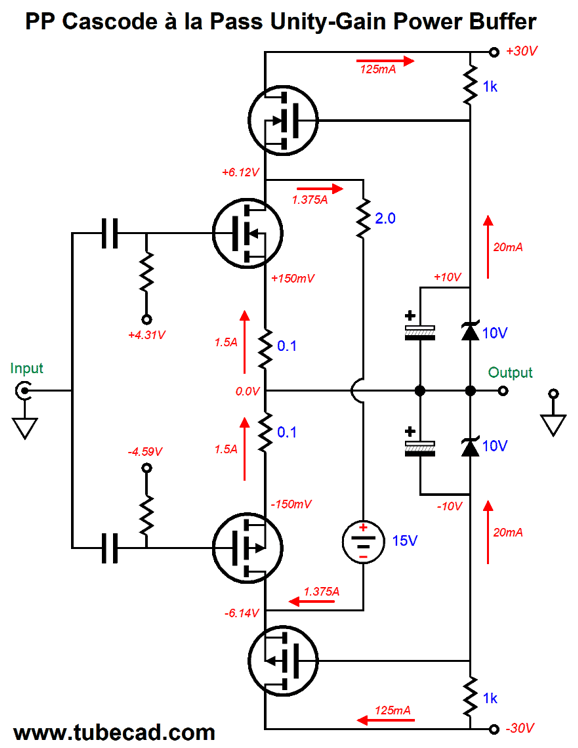
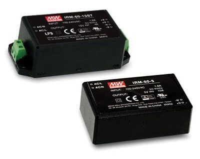
I made a few changes to part values to make for easier math, for example, 10V rather than 9.1V zeners. The center MOSFETs draw 1.5A; the top and bottom MOSFETs, 0.125A; and the floating power supply, 1.375A. Add 125mA to 1.375A and you get 1.5A. The 2-ohm resistor will dissipate 3.78W at idle, so I would use at least a 5W resistor, but 10W would be better still. Resistor ratings assume that the resistor is situated in a 25C room temperature and suspended in the middle of the room. Inside a power amplifier chassis, the temperature might be closer to 50C and the resistor might be pressed against a PCB. In other words, it pays to be paranoid. Nelson Pass's patent was made in 1994, before the advent of the cheap and ubiquitous switch-mode wallwart power supplies. Back in 1994, a conventional power supply made up from a power transformer and rectifier bridge and large reservoir capacitor was the only practical approach. Today, for less than $20, we can buy a 15V at 4A, 60W single-output AC-DC encapsulated switcher power supply.
The power supply accepts an input AC voltage of 85Vac to 264Vac and is 89% efficient. This floating power supply replaces the conventional power supply with a huge power transformer. The next step is to add it to the cascode output stage.
Note the center MOSFETs experience a current flow of 1.5A at idle, but the topmost and bottommost MOSFETs only experience a flow of 125mA.
Note the two source resistors and that the top OpAmp now sets the DC offset, while the bottom OpAmp sets the idle current. By the way, the Dc servo only works well due to the class-A amplifier biasing of the inner output MOSFETs. Also, note the 3.6-ohm resistor's 10W rating. This resistor sees a 1.3A current flow and 4.63Vdc voltage drop at idle. In contrast, the outermost cascode MOSFETs only experience a 210mA idle current flow, making for 5.2W dissipation for each. The center most MOSFET idle at 1.5A and each sees a 5.2Vdc voltage drop, resulting in 7.8W of dissipation for each. At peak power output, 36W, the floating power supply's average current draw drops to about 0.5A.
Now, let's look at the output voltage swings and the current flow through the centermost MOSFETs at full output.
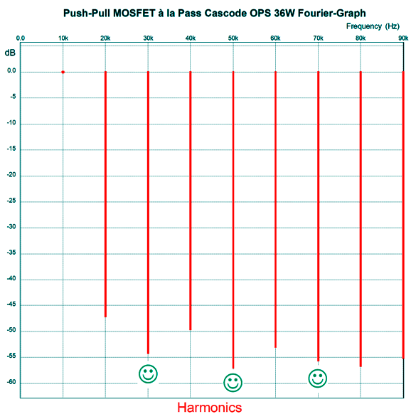
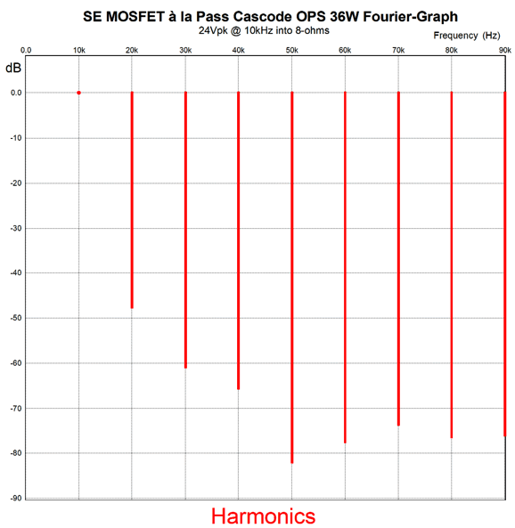
The peak output voltage swing is 24Vpk into an 8-ohm load. As we can see, the center MOSFETs never cut off completely, but the outermost MOSFET do. The top and bottom MOSFET run in class-AB, while the center MOSFETs run in class-A push-pull. If we inspect the Fourier graph for this Pass-modified cascode amplifier at full output (36W), we see an interesting group of harmonics.
Not that the 3rd and 5th harmonics are greater attenuated than the 2nd, 4th, 6th, and 8th. Usually, in a push-pull output stage, the even-order harmonics are more greatly attenuated than the odd harmonics. Bear in mind that this is a unity-gain power buffer with no negative feedback mechanism other than degenerative feedback due the source-follower configuration. The idea is that we would drive this power buffer with a high-gain tube-based line-stage amplifier.
Compound Cascode à la Pass
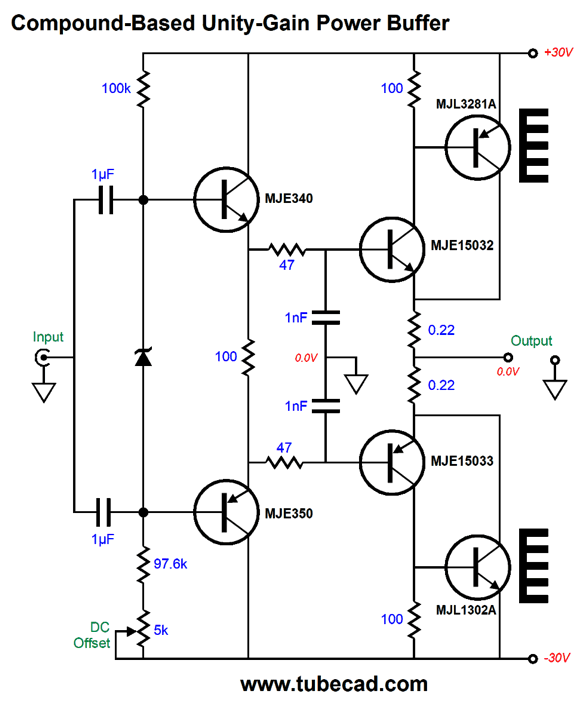
The MJE15032 NPN transistor controls the MJL3281A PNP transistor above it, while the MJE15033 PNP transistor controls the MJL1302A NPN transistor below it. These are the two local negative feedback loops. The input stage consists of the MJE340 and MJE350 emitter followers, which offer a high input impedance and low output impedance to drive the two low-pass RC filters. The compound arrangement works fantastically at low frequencies, but less so at high-frequencies. The RC filters impose a -3dB cutoff frequency of 3.4MHz. The zener diode sets the idle current flow through the output stage. The 5k potentiometer allows adjustment of the DC offset at the output. Well, Nelson Pass's novel-cascode output stage allows us to run the centermost output devices in strict class-A mode, while the outermost output devices can run in class-AB. In other words, we can get away with the compound arrangement in this topology, as it sidesteps abrupt transitions, as the compound stage never cuts off completely.
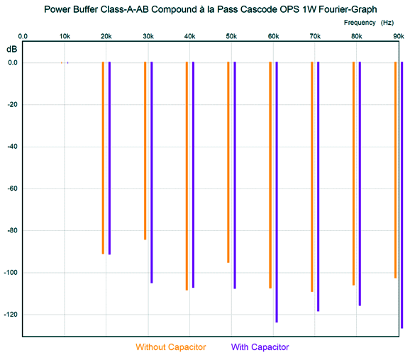
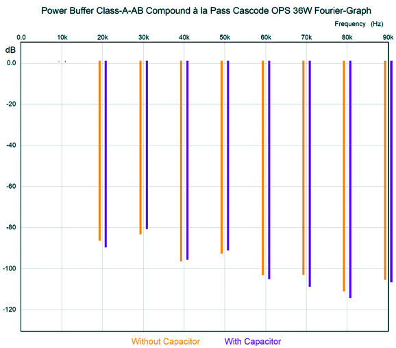
SPICE simulations presented a dilemma: choose between lower distortion at low output or at high output. In the old days, when an avid audiophile carefully noted the percent of distortion at full output, choosing the power amplifier with a splendid 0.04% THD over the one with a miserable 0.05% of THD at full output. Most listening occurs with just a few watts of power. Yes, musical crescendos will demand more power, which is why it is good to have plenty of reserve power. This is why I am in total agreement with the first-watt philosophy. If the first watt of output doesn't please, the remaining 199W are not going to compensate. Thus, the addition of the 22kµF capacitor, which forms an RC filter with the 2.7-ohm resistor. The added capacitor improves the power buffer's performance at low output wattage. Here is the SPICE-generated Fourier graph for 1W of output into an 8-ohm load at 10kHz—with and without the 22kµF capacitor.
Note the -20dB reduction of the 3rd harmonic with the capacitor in place, a tenfold reduction. With only the 4th harmonic does the capacitor-free version win, but only by an insignificant degree. Okay, let's compare results at full output.
The version with the capacitor wins the 2nd, 6th, 7th, 8th, and 9th harmonic race, but loses all the others. I would call it a draw. In both cases, the distortion is low.
LT1166 in a Pass Cascode Output Stage
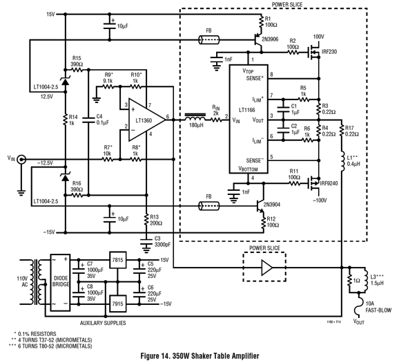
That is a lot to ask from a tiny 8-pin DIP IC. The datasheet is well worth reading, as it shows some truly interesting circuit topologies. One topology that caught my attention long ago was the one that made use of a floating bipolar power supply referenced to the output. This +/-15Vdc low-voltage floating power supply powers an OpAmp and the LT1166 that is nested with high-voltage power-supply rails.
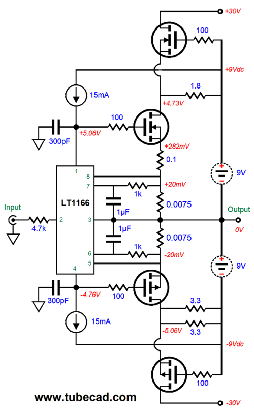
Note the +/-100Vdc bipolar power supply rail voltages. That is a huge voltage differential, enough to deliver 500W into an 8-ohm load. Okay, what if we were happy to get just 36W—but a truly fine 36W—from a power amplifier? We could use two 9Vdc switch-mode power supplies to power the class-A center output stage and the LT1166 and its two constant-current sources and bias the top and bottom cascode MOSFETs.
Note the extra 0.1-ohm source resistor for the N-MOSFET. Why? N-channel MOSFETs often exhibit greater transconductance than the equivalent P-MOSFET. This added resistor undoes some of the N-MOSFET's transconductance. The formula is simple enough. gm' = gm / (1 + gm·Rs), where Rs is the source resistor. Thus, if Rs equals the inverse of the MOSFET's transconductance, then the effective transconductance will be halved. By the way, 9V switch-mode AC-to-DC power supplies are fairly rare, surprisingly enough. At Jameco.com, we see an apparent blowout of a 9Vdc / 4.4A switcher power supply for only $3.95.
It looks decent enough. The specifications seem quite good, save for its 70% efficiency.
In contrast, many switch-mode power supplies offer efficiencies closer to 85% to 90%.
Single-Ended Cascode à la Pass Power Buffer
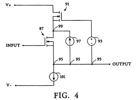
What if we apply the Nelson Pass cascode technique? Will we still retain the single-ended amplifier's low distortion without the penalty of low efficiency? Nelson's patent includes a single-ended variation, but it's not quite what we have in mind.
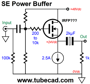
This single-ended variation can only deliver a peak negative current swing equal to the constant-current source's (CCS 101) current flow. For example, if the constant-current source current flow is set to 1A, then an 8-ohm load would see a peak negative output voltage swing of -8Vpk, which translates into 4W of power. It's peak positive current and voltage swings would be limited by the power-supply rail voltages. For example, with bipolar power supply of +/-30Vdc, the peak positive output voltage swing might be 24Vpk, which translates into 3Apk and 36W RMS of output power. So what is the point on Pass's single-ended variation? His single-ended variation would further the reduction of distortion, not the increase in output power. Let's translate his design into vacuum tubes to see how this might work.
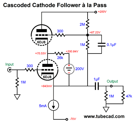
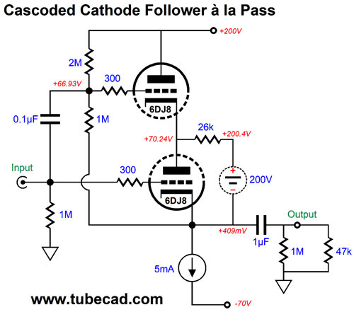
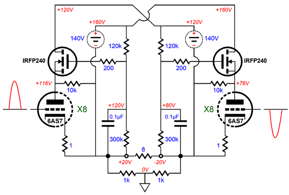
This is a cascoded cathode follower whose goal is to deliver 47Vpk into the external 47k load impedance, which implies a peak output current swing of +/-1mA peak. The bottom 6DJ8 triode sees a current flow of 10mA, while the top sees only 5mA of current flow. The floating 200V power supply delivers the missing 5mA of current to the bottom triode through the 26k resistor. Thus, the top triode dissipates 0.65W, while the bottom triode dissipates 0.7W. The bottom triode, however, operates in the more-linear region of its plate curves, due to its higher current flow and reduced plate voltage. In addition, the bottom triode experiences a fairly constant cathode-to-plate voltage throughout the huge output voltage swings. We can improve this circuit by letting the input signal drive both the bottom and top triodes.
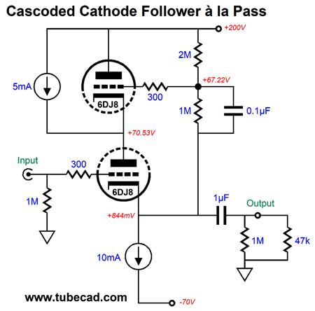
All the idle currents remain unaltered, but the top triode now sees a cleaner input signal, which further increases linearity. Interestingly, SPICE simulations will not show an accurate picture of how well these circuits perform relative to a conventional cathode follower loaded by a constant-current source. Why not? The failing is found in the SPICE triode model's fundamental assumption of a constant triode amplification factor (mu), which reality fails to deliver. (See post 538 for more information.) Here is a variation that eliminates the need for a floating power supply.
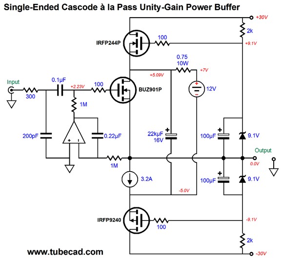
Once again, the bottom triode draws 10mA, with the top triode drawing only 5mA. Okay, we return to MOSFET-based unity-gain power buffers, specifically to one capable of delivering big single-ended-quality watts without incurring the liability of huge heat dissipation. My workaround is to encompass a single-ended output stage within a push-pull cascode output stage.
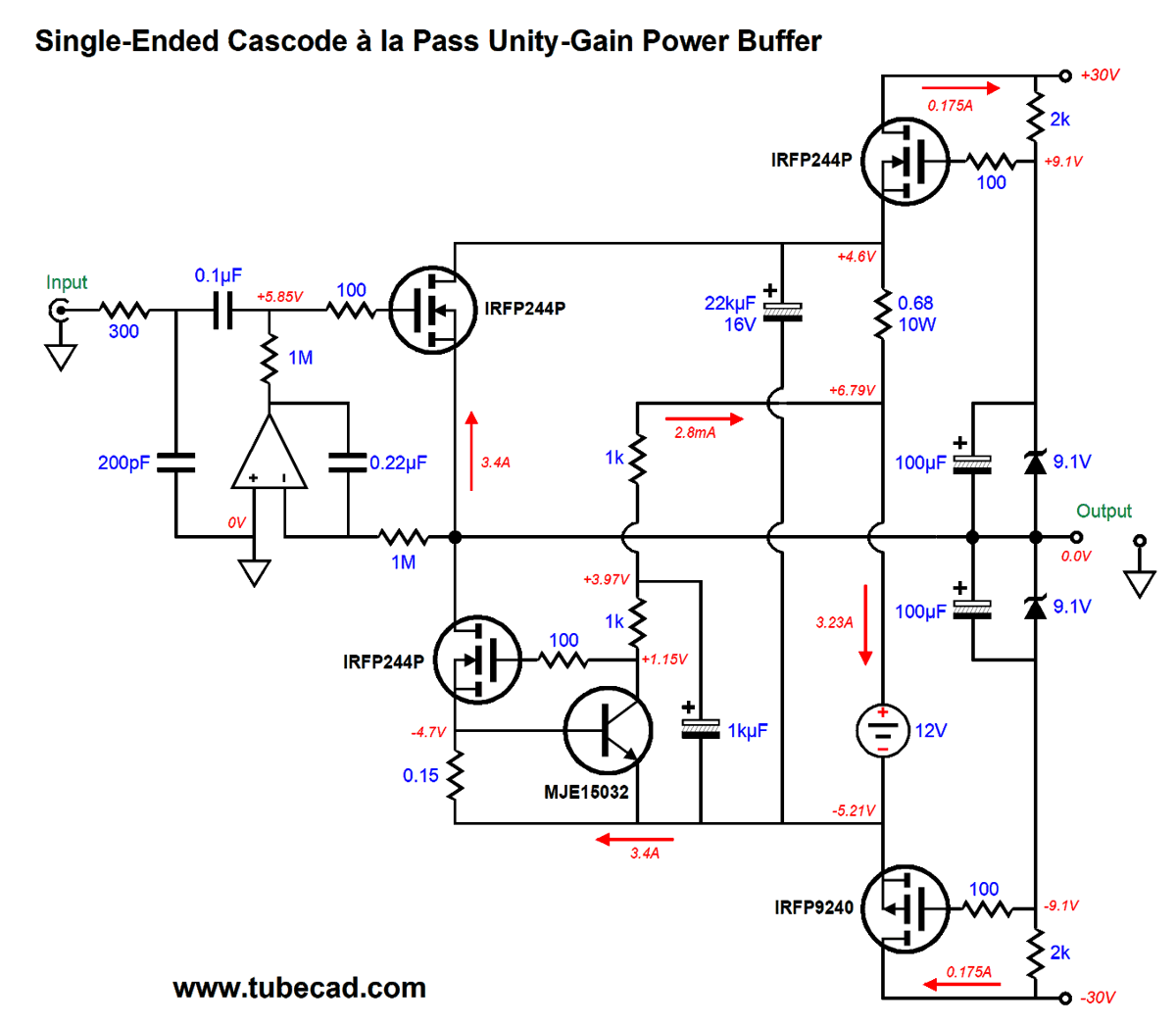
The BUZ901 lateral MOSFET idles at 3.2A, with the floating power supply and the 0.75-ohm power resistor delivering 2.57A and the top and bottom cascode MOSFET delivering 633mA, making a total of 3.2A. The DC servo prevents a DC offset voltage. The interesting addition is that of the 22kµF capacitor, which lowers distortion a tad and would certainly filter away the switch-mode floating power supply ripple. The following example shows all vertical MOSFETs and how a high-current constant-current source can be made.
Click on schematic to see enlargement The MJE15032 NPN transistor monitors the current flow through the 0.15-ohm source resistor, adjusting the MOSFET's gate voltage to maintain a constant-current flow through the resistor. (For those who are wondering if the constant-current source could be replaced with an inductor, the answer is yes. We would use the inductor's DCR as a current-sense resistance and a second OpAmp would establish a fixed DC voltage drop across the DCR. Since the inductor would only displace a fraction of the voltage that the CCS does, we could use 7.5V or 9V switch-mode floating power supplies.) How well does it work?
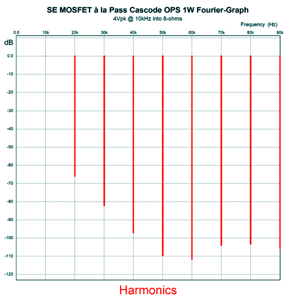
Not bad. Very single-ended. At 1W of output, the harmonic structure looks much the same as it did at full output.
Such consistency is rare. In other words, the single-ended aspect presents a single face, whereas class-AB push-pull operation produces an array of different faces.
Circlotron Cascode ala Pass
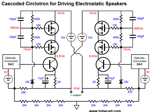
The goals behind this design are improved PSRR and a constant cathode-to-plate voltage. In post 431, I designed another hybrid cascoded circlotron, one based on transistors and MOSFETs, whose external load was meant to be an electrostatic loudspeaker.
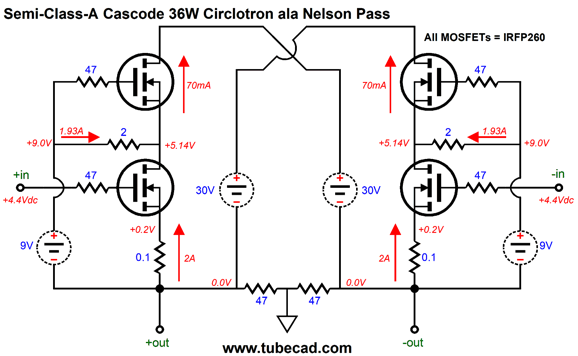
Interestingly enough, this design also makes use of two floating 5V power supplies. The DACs are driven optically and can thus force huge voltage swings, but not be referenced to ground. Well, can we implement Nelson Pass's patent technique upon the MOSFET-based circlotron? Sure. Here is how.
All the power MOSFETs are the same type. The bottom MOSFETs run under a heavy 2.37A idle current, while the top MOSFETs coast on only 252mA of idle current. The two 9Vdc power supplies are floating switch-mode types. Note that these two power supplies do not crisscross across the outputs, but are terminated at their partner MOSFET's source resistor termination. Why? In SPICE simulation the distortion was greatly improved at low output wattages. The price we must pay is a higher idle current flow for the bottom MOSFETs. Another point worth noting is that the usual two 1k resistors that couple the outputs to ground have been replaced by two 47-ohm resistors. Why? The power MOSFETs present so much input capacitance that 1k resistors produce distortion. Ideally, these resistors would be closer to 1-ohm, which would be insane, as they would receive four times more power than the loudspeaker. In addition, we would be better off either using lateral or the new SiC power JFETs and SiC MOSFETs, such as the CREE C3M0120065D, as their lower input capacitance is a big feature. The best workaround that I can think up is to use a high-quality center-tapped inductor in place of the resistors.
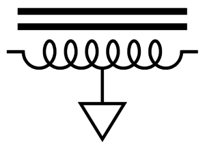
The center-tapped inductor must offer high inductance. Actually, what I would to see is an autoformer designed for circlotron use. (Someone should tell John at AnTek to make one.)
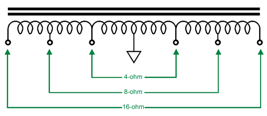
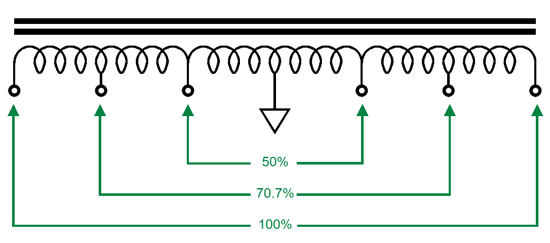
The autoformer can offer several output-impedance taps and it will put out twice the power than an equivalent transformer would with the same sized core. The winding ratios for the autoformer are simple enough:
With output taps at 32-, 8-, and 4-ohms, an autoformer would make tube-based circlotrons far more efficient and would yield far better damping factors. (listen, if you can get away with calling all circlotron amplifiers class-A, no matter how trivial the idle current flow, then you can still call this an OTL Amplifier, as an autoformer is not a transformer.)
Music Recommendation: Complete Music for Violin & Piano
"Ukrainophilic" there's your word for the day (and month). My next problem was that I don't know Lysenko's music at all. Amazon Music streaming service came to the rescue. There I found several albums of Lysenko's music. The album, Complete Music for Violin & Piano, proved to be a delight. The recording is in 24-bit at 48kHz and sounds quite good. //JRB
Very few can imagine just how much hard work is required to make one of my posts. If you have any sort of inkling or intuition of what is involved, please think about supporting me at Patreon.
User Guides for GlassWare Software
For those of you who still have old computers running Windows XP (32-bit) or any other Windows 32-bit OS, I have setup the download availability of my old old standards: Tube CAD, SE Amp CAD, and Audio Gadgets. The downloads are at the GlassWare-Yahoo store and the price is only $9.95 for each program. http://glass-ware.stores.yahoo.net/adsoffromgla.html So many have asked that I had to do it. WARNING: THESE THREE PROGRAMS WILL NOT RUN UNDER VISTA 64-Bit or WINDOWS 7 & 8 & 10 or any other 64-bit OS. I do plan on remaking all of these programs into 64-bit versions, but it will be a huge ordeal, as programming requires vast chunks of noise-free time, something very rare with children running about. Ideally, I would love to come out with versions that run on iPads and Android-OS tablets.
//JRB |
|
I know that some readers wish to avoid Patreon, so here is a PayPal button instead. Thanks. John Broskie
John Gives
Special Thanks to the Special 87 To all my patrons, all 87 of them, thank you all again. I want to especially thank
I am truly stunned and appreciative of their support. In addition I want to thank the following patrons:
All of your support makes a big difference. I would love to arrive at the point where creating my posts was my top priority of the day, not something that I have to steal time from other obligations to do. The more support I get, the higher up these posts move up in deserving attention.
Only $12.95 TCJ My-Stock DB
Version 2 Improvements *User definable Download for www.glass-ware.com |
||||||||||||||||||||||||||||||||


| www.tubecad.com Copyright © 1999-2022 GlassWare All Rights Reserved |