| John Broskie's Guide to Tube Circuit Analysis & Design |
Post 211 20 August 2011
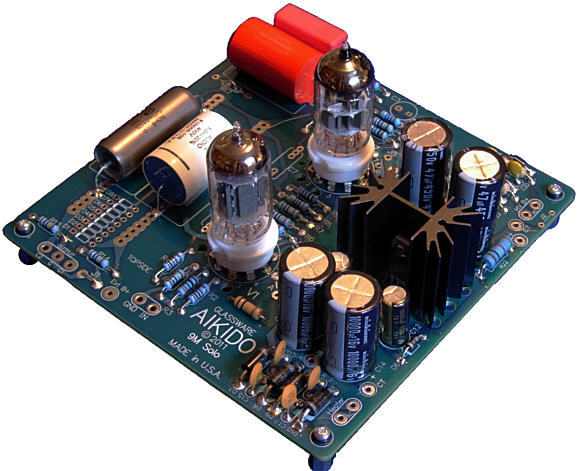
Aikido Mono Solo Okay, why yet another new PCB? A super good question, as I have already laid out many, many Aikido PCBs. Well, I designed this new Aikido board with two specific types of DIYers in mind: those who want to assemble a monobloc Moskido power amplifier and those who need a quiet and clean tube preamp for their microphones. (And let us not forget those few, but brave souls that run mono HiFi systems. If you find yourself growing weary of HiFi and audio madness, take a few-week long vacation from stereo, as listening to mono allows you to forget imaging and to concentrate on the music's tonality and rhythm. Furthermore, it often allows you hear new things in old music.) Thus, combining one channel of Aikido amplification and its heater and B+ power supplies on one board makes a lot of sense.
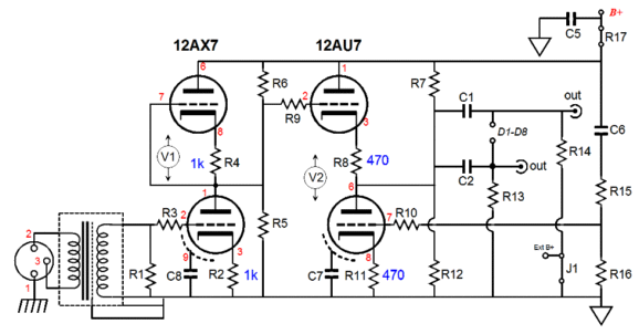
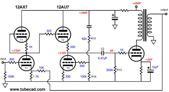
Aikido Mic Preamp
The above schematic displays a simple microphone preamp based on the Aikido Mono Solo. Much more could be easily added, such as anti-RFI ferrite beads, a resistor-capacitor network shunt for the transformer's secondary, and, possibly, a phantom power supply. Indeed, a volume control potentiometer in between the transformer and the Aikido stage would be truly essential addition. The two output coupling capacitors can either be tied together or left separated, with one large-valued and one small-valued capacitor, so that a high-pass cutoff could be selected when needed. As a 12AX7-based Aikido stage will yield a gain of only about +34dB, the step-up transformer must make up the difference. For example, a ratio of 1:20 equals +26dB, as dB gain = 20 x log(gain). This gain is added to the the Aikido's +34dB to make a total of +60dB. (Depending on the microphone, this might be too little or too much gain.) Moreover, the transformer can readily accept a balanced input signal and break ground loops and eliminate the need for input coupling capacitors.
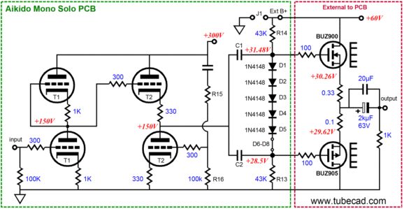
Moskido Power Amplifier
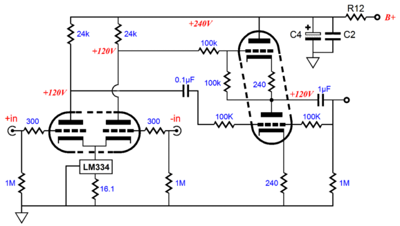
The above circuit assumes that a 12AX7 is the input tube and a 6CG7 or 12AU7 or 12BH7 as an output tube. But a much lower mu input tube can be used, such as the 12AY7 or 12AT7 or, even, a 6N1P. LT1166 Here is a quick quiz: what does the following circuit do?
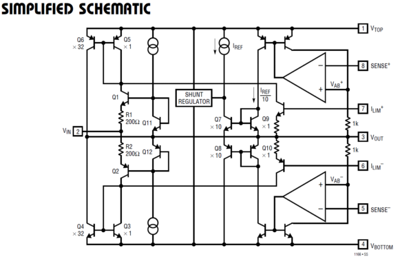
The LT1166 is an interesting device from Linear Technology. I first read about it in Robert Cordell's must-buy book, Designing Audio Power Amplifiers. Thanks Robert. The LT1166 is so interesting that I am amazed that it was ever created. (I will flatter myself—and I hope not denigrate Linear Technology—by saying that it looks like something that I would come up with.) Okay, just what does it do? It is an auto-bias/driver circuit for solid state output stages, mostly MOSFET-based output stages. Here is what the LT1166 datasheet says about it:
Read the last sentence again. That's right it operates on any supply voltage...well, any positive and negative rail voltage greater than +/-2Vdc. How is that possible? The LT1166 is safely nested within the power amplifier, tucked away from huge +/-100Vdc rail voltages. Its job is to drive and keep the power MOSFETs biased correctly, so it only sees across its leads the gate-to-gate voltage.
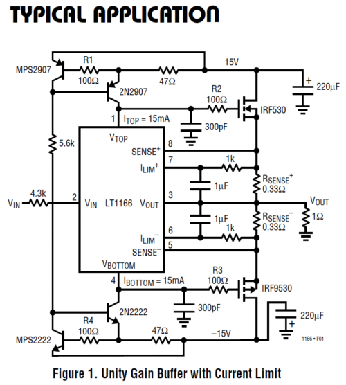
Note the 1-ohm load! Forget about diamond unity-gain buffers, such as the BUF634 this is a serious buffer. The schematic looks far more confusing than the circuit actually is. For example, the pair of transistors at the top, MPS2907 & 2N2907, and the pair at the bottom, MPS2222 & 2N2222, are arranged as simple constant-current sources. Also note the 4.3K input resistor. So, is the input impedance 4.3k? No. Its value is closer to 15M. In other words, this buffer can easily be driven by the wimpiest of tube circuits. Or, we can drive the MOSFETs directly, letting the LT1166 just do a lot of housekeeping for us, by attaching two coupling capacitors, one to Vtop and one to Vbottom on the chip. This means that the MOSFET output stage's heavy capacitance is now our concern. In other words, our tube driver stage will have to be fairly robust and must be able to swing sufficient current to charge and discharge the MOSFET output stage's heavy capacitance.
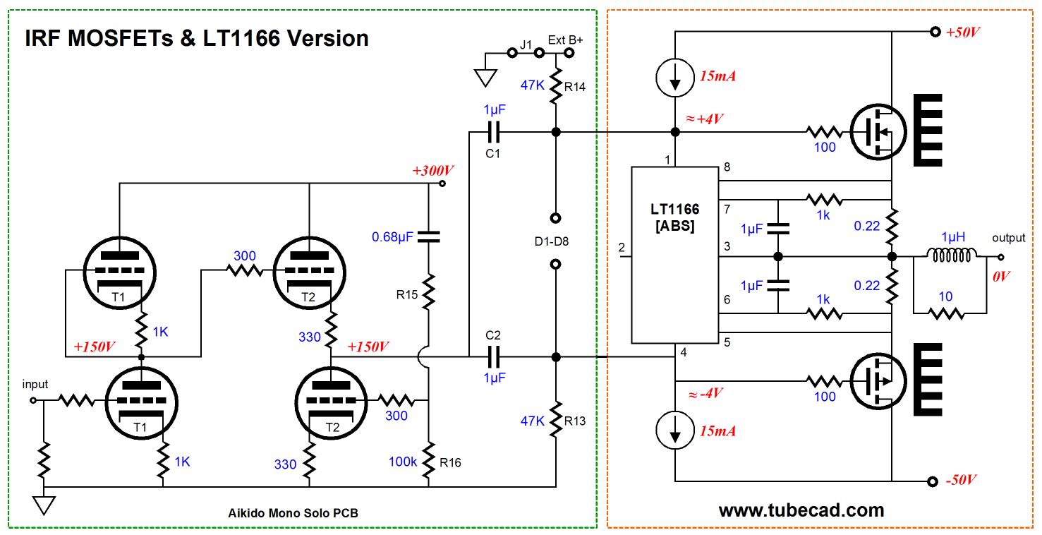
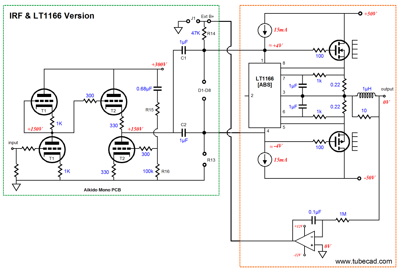
What we see above is a Moskido based on the LT1166. No doubt, a few more parts might be needed, but you get the idea. The aspect that does trouble me is DC offset at the the output. Adding a DC servo would be easy enough.
Click on schematic to see closeup The meta-view of the LT1166 is that it makes using IRF MOSFET output stages much easier. But why use IRF MOSFETs? First, they are readily available and relatively cheap. Second they are sturdy, dependable, and powerful. My own prejudice has always been in favor of "audio" type MOSFETs, such as the those lateral MOSFETs from Hitachi, Toshiba, and Magnatek. At the same time, I know that many good-sounding MOSFET-based amplifiers have been built. SO must the LT1166 only be used with IRF MOSFETs? No. In fact, the LT1166 can be used with bipolar transistors, but the circuit will require more devices, as the transistor's small base-to-emitter voltage is too small to create a useable window of voltage for the LT1166 t operate within. No doubt, the same circuit configuration will be required when using the BUZ901/BUZ906 lateral MOSFETs, as their 1.2V gate-to-source voltage will also choke the the LT1166.
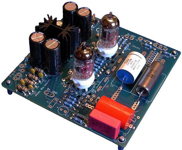
Back to the Aikido Mono Solo PCB In fact, I plan on using two of the boards myself, as I plan on building two monobloc single-ended power amplifiers using the new PCB. By using a 12AX7 as the input tube, the AIkido stage will yield a gain of 50 (+34dB), which would be plenty for driving a single KT120 tube to full output. On the other hand, if three or five EL84 tubes were used in parallel, then a 6CG7 or 6DJ8 or 12AU7 would offer sufficient gain (I assume that no negative feedback loop would be used). The Aikido Mono Solo printed circuit board holds two 9-pin triodes, such as the 6AQ8, 6BQ7, 6DJ8, 6CG7, 6FQ7, 6GM8, 6H30, 12AT7, 12AU7, 12AV7, 12AX7, 12BH7, 5751, 6922, ECC99…as the input or the output tube; and the 5687, 6900, 7044, 7119, 7370, and E182CC can be used as the output tube, but not as the input tube. By the way, I often am asked how to use a negative feedback loop with an Aikido input stage. Assuming that he amplifier is non-inverting, the following circuit shows how to attach the feedback resistor.
The 12AX7-based in pout stage uses a 1k cathode resistance for both the top and bottom triodes, as the bottom 1.1k resistor in parallel with the 10k feedback resistor equals 1k. (In parallel with, whose symbol is ||, follows this formula By the way, the Aikido Mono Solo PCB can be used upside down; all the parts other than the two tube sockets can be soldered in the bottom sid of the board, so the PCB can be mounted close to the chassis's top plate with the tubes protruding through two holes. (The heater regulator has a second set of solder pads on the bottom side of the board.)
The Aikido Mono Solo PCB and kit is available at the GlassWare-Yahoo store. (I only have 18 PCBs, so it's first come, first serve...maybe, only serve.)
VIAS
As far as I can tell, what they are doing is finding old, classic—out of copyright—technical books and scanning and OCRing them. A great public service, in other words. For example, we can read and download Norman H. Crowhurst's three volume set, Basic Audio. In addition, Reuben Lee's masterly tome, Electronic Transformers and Circuits, is found here as well. (I love this book and I used to own a copy, but I lent it out one too many times.) Check it out.
Passive Line Stage Vs Unbalancer
Vs
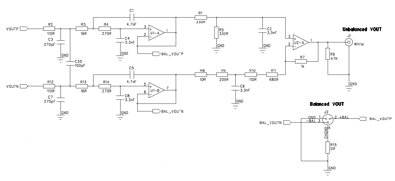
I had just been listening to my Unbalancer circuit, which I like a great deal. After swapping out the active line stage for the passive one, I immediately longed for the Unbalancer's return. Less was not more this time. How strange. I have often noticed that active can sound better than passive, in spite of all the extra stuff in the signal path, but this listening event seemed different. Just in case the passive line stage needed breaking in, which makes little sense to me, as I don't see how resistors, wire , and switches need any breaking in, but I let the music play for the rest of the day nonetheless. (I once built a special box for breaking in speaker and line cables; it held a wall socket and a power cord that plugged into the wall outlet, and four RCA jacks and eight binding posts. With this box I could run 120Vac at 1A through either two patch cords or two speaker cables at once, as they completed a circuit with a floor lamp. With the speaker cables, I often plugged in the TV as well. After a few days of this serious voltage and current, I figured the cables had to be broken in.) I then held a second shootout and, once again, the Unbalancer clearly won again. Weird, very weird. I checked all the wiring in the passive unit and everything was correct. Now understand, I wasn't actually comparing apples to apples, as the Unbalancer used XLR terminated balanced cables and the passive line stage used unbalanced, RCA-terminated cables. But here was the odd thing, the RCA line cords cost a bundle $$$, whereas the XLR cables cost $20 the pair. I thought about it and then it hit me, hit me hard: the Unbalancer was getting its balanced input signal in front of the passive line stage, as the following schematic illustrates.
In other words, the passive line stage was seeing an additional OpAmp and a bunch of resistors and capacitors in its signal path, so I was comparing one apple to two apples (or more apples). What to do? The interesting thing about the Unbalancer circuit is that it can readily accept an unbalanced input signal. Just feed either its inverting or its non-inverting input an input signal and leave the other input grounded. This is exactly what I did, feeding both the passive line stage and the Unbalancer the same double-OpAmp signal, using the same expensive RCA-terminated cables. Now it was one apple against one apple. So, who won this time? Well, it was no longer decisive. In fact, it was a complex mix of results. At times I preferred the passive line stage, as it seemed to offer more subtle details; but, at other times, I preferred the Unbalancer, as it seemed to present a wider, more solid and believable sound stage, depending on the music playing. Sometimes it was not a fair fight, as the CD was recorded at such a low volume that the passive line stage could not fully power the amplifiers. The conclusion that I walked away with was that the Unbalancer is a great-sounding circuit. On the other hand, the passive line stage is wonderfully simple, inexpensive, and "green" as any audio component can be, as it draws no power from the wall outlet. (Of course, if the exact same attenuators were sold in a finished box, complete with a thick front faceplate and huge expensive knobs, built by a high-end company, the passive line stage would cost well over $1,000; with fancy resistors, several thousands of dollars. And, of course, for many audiophiles, it would—perforce—sound much more exalted, as befits a new, more dignified price tag.)
Next Time
//JRB |
I know that some readers wish to avoid Patreon, so here is a PayPal button instead. Thanks.
John Broskie
And
High-quality, double-sided, extra thick, 2-oz traces, plated-through holes, dual sets of resistor pads and pads for two coupling capacitors. Stereo and mono, octal and 9-pin printed circuit boards available.
Designed by John Broskie & Made in USA Aikido PCBs for as little as $24 http://glass-ware.stores.yahoo.net/
The Tube CAD Journal's first companion program, TCJ Filter Design lets you design a filter or crossover (passive, OpAmp or tube) without having to check out thick textbooks from the library and without having to breakout the scientific calculator. This program's goal is to provide a quick and easy display not only of the frequency response, but also of the resistor and capacitor values for a passive and active filters and crossovers. TCJ Filter Design is easy to use, but not lightweight, holding over 60 different filter topologies and up to four filter alignments: While the program’s main concern is active filters, solid-state and tube, it also does passive filters. In fact, it can be used to calculate passive crossovers for use with speakers by entering 8 ohms as the terminating resistance. Click on the image below to see the full screen capture.
Tube crossovers are a major part of this program; both buffered and un-buffered tube based filters along with mono-polar and bipolar power supply topologies are covered. Available on a CD-ROM and a downloadable version (4 Megabytes). Download or CD ROM
|
|||


| www.tubecad.com Copyright © 1999-2011 GlassWare All Rights Reserved |