| John Broskie's Guide to Tube Circuit Analysis & Design |
| October 20 2025 | Post Number 627 |
||||
Happy Halloween
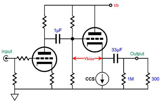
Single-Tube, Two-Triode Magic My last post held many single-tube, two-triode designs, which amazed me with their ability to deliver so much with so little. In contrast, an audio IC can easily contain a hundred parts, resistors, capacitors, diodes, transistors… Here is an example of a simple two-triode design from Post 626:
The only cheat was the constant-current source, but it can be replaced by a single LM317 and one resistor; failing that, we can replace the constant-current source with a large-valued cathode resistor that terminates into a negative power-supply rail. The triode on the left provides all the signal gain; the one on the right; current delivery. The external load impedance of 300 ohms represents a headphone driver. While going through old email, I found a line-stage amplifier circuit that I had sent a friend. The circuit was also a two-triode affair that delivered less gain and a higher but still low output impedance.
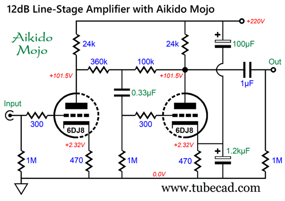
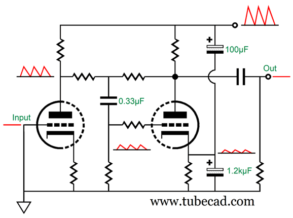
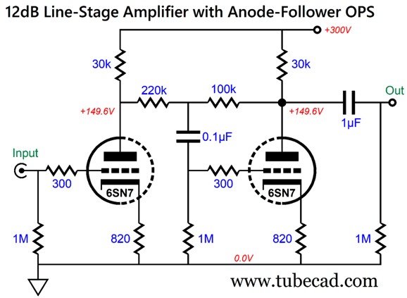
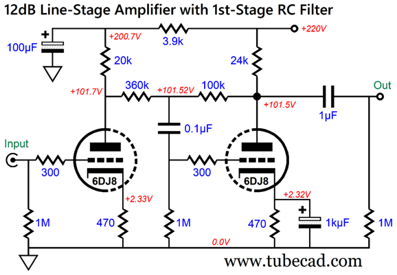
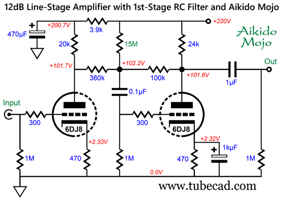
This line-amplifier circuit had three goals: only 12dB of gain; some harmonic enrichment, where the triode's glory would shine; and a good PSRR figure. Several unsought features fortuitously appear, such as the same triode cathode voltage, which sidesteps the CCDA's heater issue of having a large voltage differential between cathodes.
If the B+ voltage were 300Vdc, the cathode-voltage difference between triodes would be 150Vdc, which would absolutely require referencing the heater power supply to 75Vdc. By the way, the CCDA's PSRR is only -6dB. Another feature is that the cascade of a grounded-cathode amplifier into an anode-follower (aka plate follower) results in no phase inversion at the output. By the way, if we replace the 24k plate resistors with 5mA constant-current sources, we get stellar PSRR and the ability to use a much lower B+ voltage.
(The unspecified negative feedback resistor must be calculated to compensate for the high gain from the first stage with the constant-current source loading.) Returning to the original 12dB line amplifier, the one potential problem is the getting the right capacitor values for the Aikido Mojo to work well. Electrolytic capacitors come in very coarse capacitance increments based on the following base values 1, 1.1, 1.2, 1.3, 1.5, 1.6, 1.8, 2, 2.2, 2.4, 2.7, 3, 3.3, 3.6, 3.9, 4.3, 4.7, 5.1, 5.6, 6.2, 6.8, 7.5, 8.2, 9.1; this is the E24 spread of base values, which hold 24 values; E48, 48 values. In addition, electrolytic capacitor tolerance is usually a sad 20%. In contrast, we can get resistor values in much finer gradations and with much tighter tolerance (E96 and E192), as little as 0.01%, even 0.001%. But before we abandon the two-capacitor Aikido Mojo technique, we should see how it works.
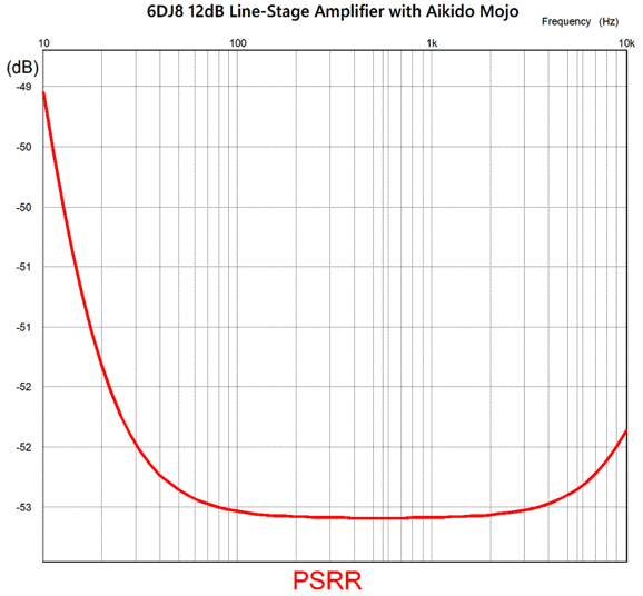
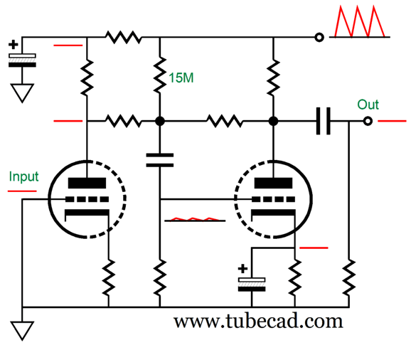
Without the second cathode capacitor, the one that bridges the cathode to the B+ voltage, the power-supply noise appears at the output in anti-phase to the ripple. This means that the triode on the right has over amplified the amount of ripple appearing at its grid, so we must introduce a small sampling of the ripple to its cathode to create a power-supply noise null at the output. In SPICE simulations, the PSRR at 100Hz was -53dB, using the 0.33µF, 100µF, and 1.2kµF capacitor values.
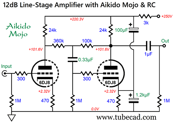
I must point out that this is only the raw PSRR, which does not include any of the usual PSRR-enhancement techniques usually applied to power supplies, such as chokes, RC filters, and regulation. For example, by increasing the B+ voltage a tad and inserting a 3k series power resistor, we get a vastly greater PSRR, as electrolytic capacitors and added resistor form an RC filter, whose -3dB frequency is below one Hertz (0.57Hz).
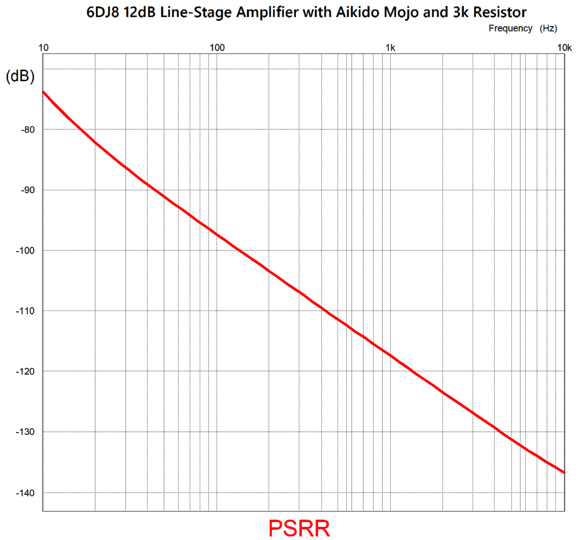
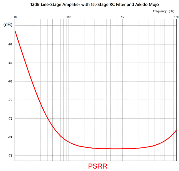
Here is the resulting final PSRR with the RC resistor:
This is close to one hundred times better.
2nd Aikido Mojo Approach
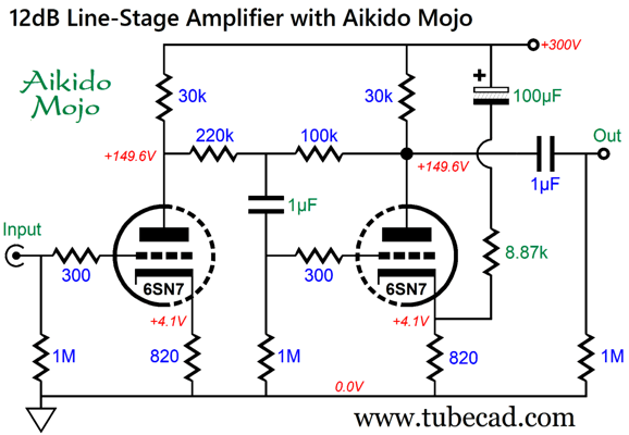
The PSRR without any Aikido-Mojo magic is a paltry -19dB; with Aikido Mojo, -78dB, an almost 60dB improvement, which translates to a 1,000 fold improvement. In other words, 1V of ripple is reduced to 1mV; 1mV to 1nV. What is required are an additional resistor and capacitor.
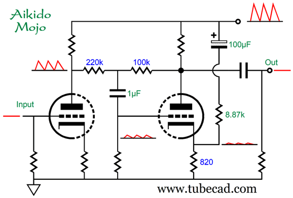
Note that the internal coupling capacitor value has been increased to 1µF from 0.1µF. Both this capacitor and the 100µF electrolytic capacitor can be increased in value, but shouldn't be reduced in value. The principle behind this Aikido-Mojo variation is the same as before, but uses a two-resistor voltage divider rather than a two-capacitor AC signal voltage divider. (The 100µF capacitor terminating into the B+ voltage is effectively, in AC terms, a dead short.)
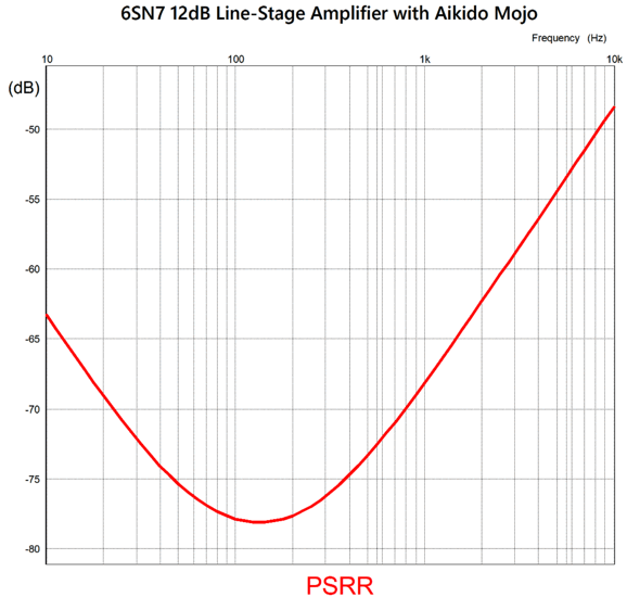
Since the 6SN7 offers a lower amplification factor (mu) than the 6DJ8, the anode follower's negative feedback resistor ratio differs from the 6DJ8-based design example. Here is the SPICE-generated PSRR graph.
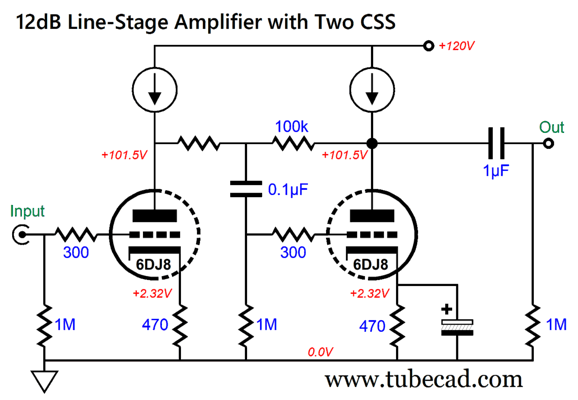
If we rather use a 6DJ8, we must alter the part values; and we can lower the B+ voltage.
The PSRR for this circuit is -72dB at 100Hz. Not bad, but we can do better. Let's start with a core circuit and then add the Aikido Mojo.
3rd Aikido Mojo Approach
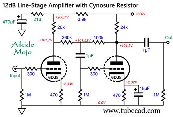
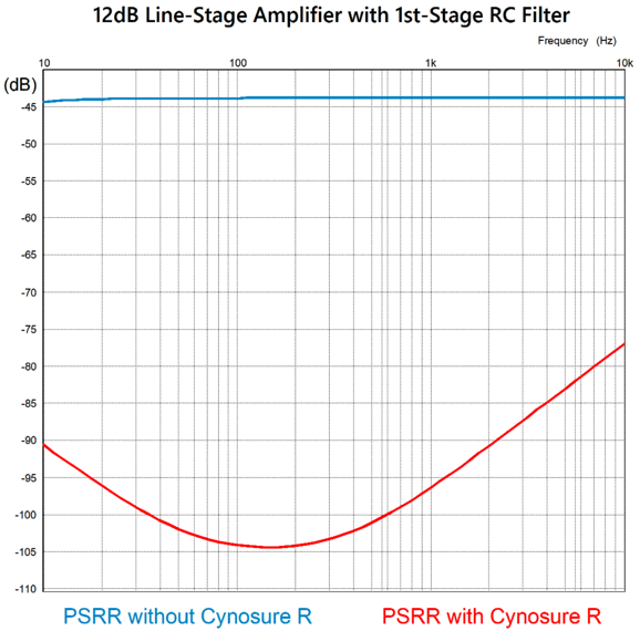
Also note the anode follower's cathode resistor is now bypassed with a large-valued capacitor, which will result in a lower output impedance. The addition of the B+ voltage RC filter delivers a PSRR of -44dB. If we add one resistor, however, we get a vastly improved PSRR.
"Cynosure" means an object that serves as a focal point of attention and admiration. The word derives from the Ancient Greek word for dog tail, kunosoura, which became in Latin, cynosure. Well, this dangly resistor reminds me of a dog's tail. (See Posts 426 and 536 for more cynosure designs.) While I am at it, I will point out that Aikido is the Japanese martial art that uses one's opponent's aggression against him, while the Aikido Mojo uses the power-supply noise against itself. (A friend once said, "I like hearing John talk, as he is not only entertaining, but you also earn college credits at the same time.") We no longer have to inject some power-supply noise into the anode-follower's cathode to force a power-supply-noise null, as we can limit the amount leaking from the input stage to create the desired power-supply noise null. We do this by undoing some of the RC filter's filtering. Yes, by doing less we get more.
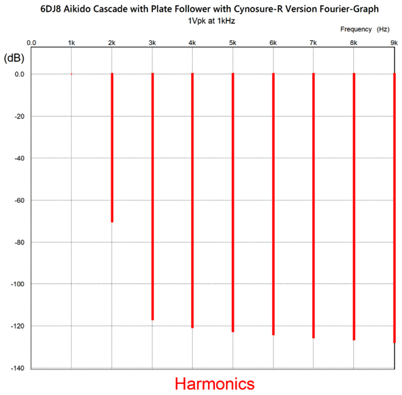
If you are wondering what the distortion is like leaving this circuit, here is the Fourier graph of harmonics based on an output signal of 1Vpk at 1kHz.
The THD is below 0.1%. Note the strong 2nd harmonic and the greatly reduced higher harmonics. Next, we see the PSRR graph.
That's some PSRR!
Another Aikido Mojo technique is to feed the anode follower's negative feedback loop directly with a resistor.
The assumption here is that, due to the RC filter, the input stage does not leak much power-supply noise at all.
The resulting improvement isn't as great as the previous variation due to resistors in the 15M range no longer are offered in tiny resistance increments, but the coarse E24 spread of values.
While this PSRR is not as good as the previous variation, it's exemplary.
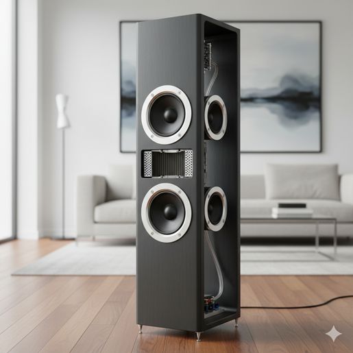
Artificial Intelligence Image Creation
A ridiculous design, but nonetheless effing amazing. I often bemoan my inability to 3D model, as it would come in so handy in illustrating my new ideas. Hell, if AI is this good, do I really need to learn how to use a 3D modeling program?
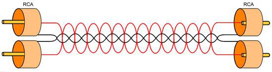
Back to the Past Designs, what designs? It's just wire after all, so what design choices can exist? If we are only dealing with two wires, we have at least the choice between twisted or untwisted. (Of course, we have left out coaxial cable with a single wire surrounded with shield, which cannot be twisted.) In addition, we can add ferrite beads or magnets to the two-wire interconnect. (Do not laugh. They are added and the cables sell for hundreds of dollars.) Even if we are left only with twisted or untwisted, we can opt either for a constant twist or a twist that spins in the opposite direction somewhere along the length. Since stereo long ago beat mono, we usually have two interconnects, not one. Thus, we can get fancy by braiding to pairs of wires.
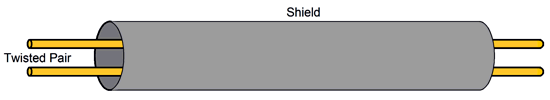
I actually just made this arrangement, but have yet to listen to it. Now let's add a shield to our two wires and things get interesting.
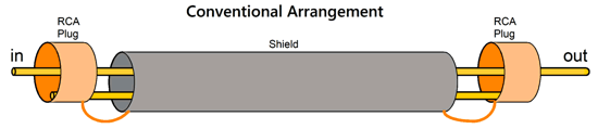
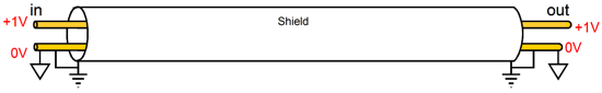
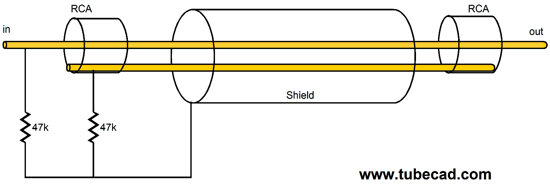
The usual setup grounds the shield at both ends.
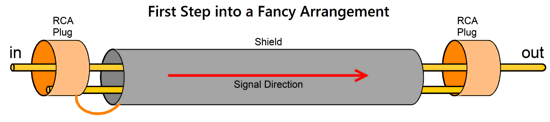
This is how most non-audiophile-grade interconnects are made. Note that it makes no sense to treat this interconnect as being directional. It's considered bad form, however, to allow current to flow through a shield, so the following modification is made.
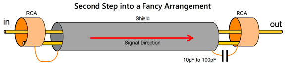
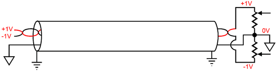
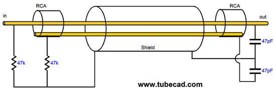
The shield is not only grounded at one end, so no current can flow through the shield. The new problem is that the unterminated shield acts like an antenna; not good. The workaround is to add a tiny-valued capacitor.
No DC current can flow through the shield and only a trickle of ultra-high-frequency signal can jump across such a small capacitance, as a 10pF capacitor exhibits an impedance of 800k at 20kHz. But this is enough to stifle the antenna-like properties of the shield.
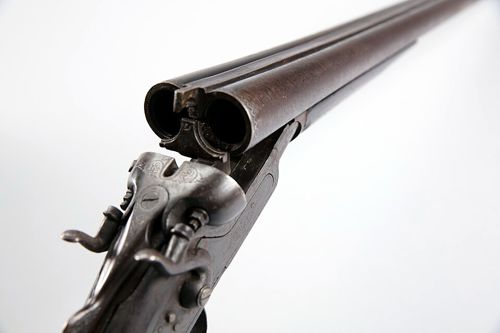
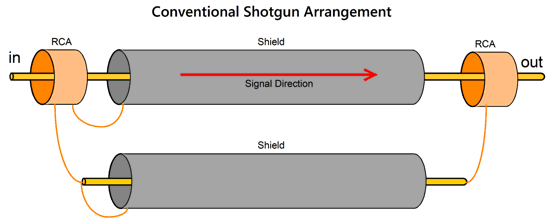
Another addition we can make is to go shotgun (i.e. double-barrel shotgun), the use of two shielded cables with any number of internal wires. The bulk Teflon wire I got held a two-wire twisted lead inside the shield. I treated the two wires as a single wire.
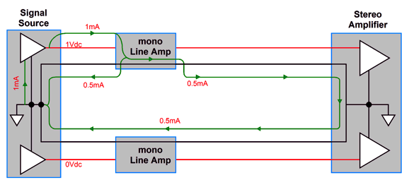
If nothing else, we have halved the DCR of the wire, as both the hot and ground got two twisted wires, rather than one wire. Moreover, the dirty little secret of stereo practice is that an audio signal, in just the right channel, will provoke equal return current flow through both the right and left channel interconnects with a stereo power amplifier, which using a dual-mono line-stage amplifier will not change. Why not? The current flow does not know that it must belong to only the right channel and allow current flow only I the right channel's interconnect, as it simply takes the path of least resistance; in this case, the two ground paths offered by both interconnects present equal resistance, so the current flow down both. By the way, the RCA plug and jack was a huge blunder; instead we should have used something like a three-pin XLR connector that would hold right and left pins and one ground pin. See my Post 434 for more details.
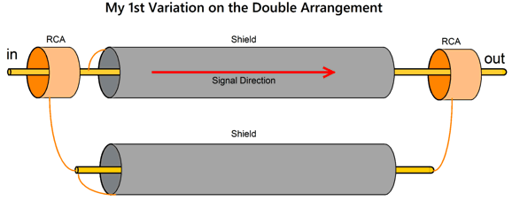
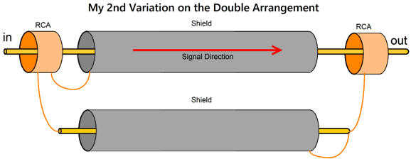
Well, with the shotgun arrangement, we effectively have isolated the right channel's return currents from the left channel's hot cable (and have created duplicate ground-return paths). I believe this explains why the double-shotgun often sounds better than the single barrel cable. My first attempt at making a fancier double-shotgun was the following:
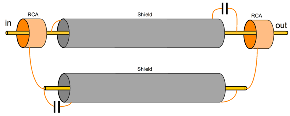
The hot cable uses a driven shield, i.e. a shield that sees the same signal as the hot wire inside. How did it sound? Different certainly, but not to my taste, as the high-frequencies seemed a tad too forward, but your mileage may vary. If we add antenna-nulling capacitors, the interconnect will look like this:
My second attempt made two changes—both applying to where the shields attach.
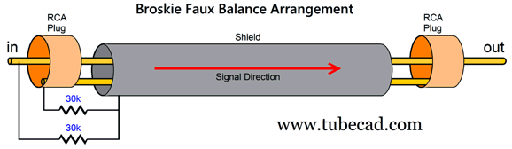
Okay, this new interconnect arrangement won my heart and ears, as it delivered the biggest stereo image. So, are we done? No. I decided to resurrect an interconnect design I had created in the mid-1980s, the Broskie Faux-Balanced interconnect.
Dang. It beat my last variation on the double-shotgun. I value stereo imaging greatly, and this 40-year-old design delivers it. How does it work? Here is what I said in post 240:
Well, our old friend Thomas Sterns Eliot put it best:
Here's a crash course in interconnect designs:
Speaker cables:
Music Recommendation: Audiophile Hi-Res System Test
//JRB
AI Summary
Did you enjoy my post? Do you want to see me make it to post 1,000? If so, think about supporting me at Patreon.
User Guides for GlassWare Software
For those of you who still have old computers running Windows XP (32-bit) or any other Windows 32-bit OS, I have setup the download availability of my old old standards: Tube CAD, SE Amp CAD, and Audio Gadgets. The downloads are at the GlassWare-Yahoo store and the price is only $9.95 for each program. So many have asked that I had to do it. WARNING: THESE THREE PROGRAMS WILL NOT RUN UNDER VISTA 64-Bit or WINDOWS 7, 8, and 10 if the OS is not 32-bit or if it is a 64-bit OS. I do plan on remaking all of these programs into 64-bit versions, but it will be a huge ordeal, as programming requires vast chunks of noise-free time, something very rare with children running about. Ideally, I would love to come out with versions that run on iPads and Android-OS tablets.
|
I know that some readers wish to avoid Patreon, so here is a PayPal button instead. Thanks. John Broskie
John Gives
Special Thanks to the Special 91! To all my patrons, all 91 of them, thank you all again. I want to especially thank
I am truly stunned and appreciative of their support. In addition I want to thank the following patrons:
All of your support makes a big difference. I would love to arrive at the point where creating my posts was my top priority of the day, not something that I have to steal time from other obligations to do. The more support I get, the higher up these posts move up in deserving attention.
If you have been reading my posts, you know that my lifetime goal is reaching post number one thousand. I have 375 more to go. My second goal was to gather 1,000 patrons. Well, that no longer seems possible to me, so I will shoot for a mighty 100 instead. Thus, I have just 9 patrons to go. Help me get there. Thanks.
New URL of the GlassWare website |
||||

.png)


| www.tubecad.com Copyright © 1999-2025 GlassWare All Rights Reserved |