Post 240 27 August 2012
Now that wires will soon be added to the list of superseded electronic parts, along with the vacuum tube and turntable, it is time for me to write about audio cables. Over the last 13 years, I have made fun of high-end cables, both the cables themselves and their makers. Remember Sonic Gold at Silver Prices. They are, whatever else their attributes, easy targets. All audio-gear makers must puff their products, but with cable makers we get the feeling that there is little behind their wares beyond the puffing. It is just wire and sheathing after all, in spite of all the glossy ads filled with phrases, such as time-coherent metallurgy or holographic space-time continuum mono-crystalline quantum nano technology...
Just ask yourself the following question. Which audio system is more likely to sound better: the one with $100 speakers and $20,000 speaker cables or the one with $20,000 speakers and $100 cables? If you chose the latter system, then we probably agree that high-end sellers of $20,000 power cords should not be allowed to die a natural death. On the other hand, if you refused to choose either system, holding out for the the system that held both $20,000 speakers and $20,000 cables, then you are a true audiophile, which may not be quite the designation of distinction that you might imagine.
No doubt, most of the public would judge buying $20,000 speaker cables foolish, but then so, too, they would judge buying $20,000 speakers or amplifiers or DACs or turntables...foolish. One man's peculiarity or eccentricity is another man's deviancy. At least, however, $20,000 speaker cables persist, whereas $20,000 bottles of wine are swallowed in an hour. And if you are lucky enough to be Bill Gates, in terms of money in the bank, not in terms of looks or personality or charm or wit or... , then why not buy $200,000 or, better still, $20,000,000 speaker cables? You could not live long enough to burn all your money.
(You must understand that I have never forgiven Bill for his book, The Road Ahead, one of the saddest waste of paper and ink that I have ever read, unbelievably lame; written as it was by a computer industry leader, its vacuity was truly unpardonable. In fact, this book is so unremittingly stinky that I can only assume that he wrote most of it himself. If this is not the case, them Gates should sue his ghostwriter for malpractice.)
Unlike Mr. Gates, most of us are constrained by both limited cash and finite spousal approval. And, I would add, we should be constrained by something like an aesthetic sensibility or just plain good taste. Surely there is something vulgar and repellent about the ultra-expensive dreck sold on Rodeo Drive in Beverly Hills, whose purchase betrays a want of inherent nobility and inner worth. We should strive for a harmonious relation of parts within a whole and a sort of dignity, self-respect, within which $20,000 speaker cables are incompatible. Of course, like the length of a skirt, the ratio between speaker cost and cable cost is subject to debate, but parity is obviously obscene. My own position (or prejudice) would be that the cables should never cost more than 10% of what the speakers cost.
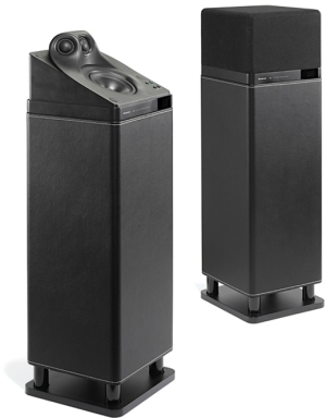
The future doesn't look good for cable manufactures, as the following speaker intimates. Audio Pro is not the only speaker company to forgo wires, for example Focal also make wireless speakers.
Who doesn't hate wires cluttering up a listening room? As Carl Marx might have put it: Audiophiles of the world go wireless; you have nothing to lose but your cables. Or, as Voltaire might have put it: It is difficult to free fools from the cables they revere.
Having said all that, I do believe that cables make a difference, that they do sound different, some better, some worse. But before digging into the details, we should acknowledge the huge practical difficulties in testing cables sonically. Huh? You plug them in and you listen; that's it, the end. What difficulties? Okay, here are some interesting scenarios: you listen to your old interconnect, then you plug in new interconnect and it sounds much better. Great, except the same interconnect was reattached. You try a new interconnect and it sound worse than what you have been using; you reattach the old interconnect and it now sounds bad. You are at the high-end-audio store or a friend's place and you listen to a cable shootout and one cable triumphs, so you buy it; but in your system, it sounds worse than your old cable. All of these experiences have happened; if not to me, then to a friend of mine.
I once worked with that rarest of people, a female audiophile (not a crazy hard-core audio nut, but an Audio-magazine-reading audiophile with a fairly expensive system at the time). She had a bad case of upgrade fever and she was about to set her credit card ablaze. She asked for my recommendations. I wanted to hear what she was listening to at the time. I had to agree with her: her system sounded dull, in spite of the quality components. This bothered me, as it should have performed better. So, I went to work.
I clipped off the oxidized ends of the speaker cable, exposed fresh copper, and polished the speaker's terminals, then I did the same at the amplifier outputs. I adjusted the VTA on the tone arm and cleaned all the phono cartridge contacts and sprayed contact cleaner on the selector switch contacts. I was a huge fan of Cramolin® back then and I diluted both the red and blue liquid in laboratory-grade alcohol, which I then applied to all the contacts. After about half an hour of work, we fired her system up and listened. A metamorphosis, a transformation, a rebirth—all together beyond what either of us expected.
It is possible that only one set of dirty contacts had poisoned the entire system, but I took care of all of them, including the wall sockets. But let's say that just the RCA jacks on her preamp outs were to blame. Had she been talked into buying $1,000 interconnects, the very act of pulling off the old interconnect and pushing on the new cables might have been enough to clean the contacts sufficiently to transform the sound and she would have falsely attributed the improvement to the new interconnects.
And how about, You try a new interconnect and it sounds worse than what you have been using; you reattach the old interconnect and it now sounds bad. Sad to say, but not all interconnect prongs are equal in diameter. A new interconnect may force the RCA jack beyond its ability to contract (the RCA plug and jack are obscenely lame constructions), so now your old interconnect never makes solid contact with the RCA jack.
And finally, You are at the high-end-audio store or a friend's place and you listen to a cable shootout and one cable triumphs, so you buy it or borrow it; but in your system, it sounds worse than your old cable. Another system is another system, with different flaws and assets, sounding in a very different room. If the other system sounds too bright, due to a hot tweeter or poor RIAA equalization or a sizzling amplifier, then a dull-sounding interconnect may prove a blessing. But if your system suffers from slightly reticent highs, then the dull cables will push the sonic balance into the grave.
In other words, even the tasks of testing and evaluating interconnects are difficult.
Back in the late 1970s, while in college, a few of us audiophile types got together to do an interconnect shootout. We had gathered as many RCA-plug-terminated
cords that we could find. Most were super cheap, the sort of cables that came with budget turntables and cassette decks. A few were more expensive cables that could be bought at electronic-supply stores. Only one cable was a high-end creation that cost a stately sum of $30, an outrageous expense back when we paid less $200 in monthly rent. The clear winner came from Radio Shack and it was sheathed in gray polyvinyl and cost about $5. The $30 cable sounded different, but not better, but definitely different. This intrigued me, so I disassembled its RCA plug and found that each end held a small resistor and ceramic capacitor wired in series and placed across the positive and ground.
Around that time, Peter Moncrief, International Audio Review’s editor, had written that TV antenna 300-ohm, solid-core, twin-lead made excellent interconnect cable. I built up a cable and I was impressed, in spite of my baseless fears that an unshielded interconnect would prove a hum magnet. The secret was to get twin-lead made of pure copper, not copper-plated steel.

Of course, I could not leave well enough alone; I had to modify. First, I tried twisting the cable into a helix, but I couldn't get it to retain its shape for long.

My next experiment was to cut some of the webbing away, so I could force two carefully spaced twists in the twin-lead.
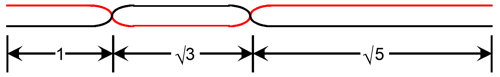
My idea at the time was that good interconnects should make bad antennas, so I wanted to impose non-constructive ratios on the cable.
When Audio Amateur began selling bulk Mogami microphone cable, with four conductors made from oxygen-free copper strands, I bought yards and yards of the cable in three different colors, blue, yellow, and black.
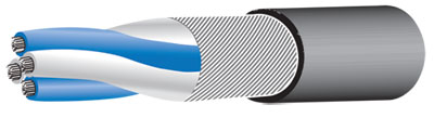
I loved the feel of the cable and the ease of working with it, but it didn't sound better than the twin-lead and other cables I had tried; if anything, a bit worse. While the bass was solid, the highs were lackluster. I mentioned my
dilemma
to friends and one told me that he had removed the outer shield, leaving the four conductors in a tightly twisted strand. I gave it a try and I thought the sound improved, but I didn't like having the twisted conductors unwind. Another friend recommended shotgunning the cables, wherein two cables were used per channel, with all four conductors tied together, so each channel's positive and ground would get four conductors; the shield was to be attached to the ground at only one end, usually the end that attached to the signal source. This resulted in a major improvement in sound; it looked cool, as well.
Then in the late 1980s I read in the British HiFi magazines about Denis Morecroft and his views on thin, solid-core interconnects and speaker cables. I was impressed, for the most part. I set off looking for thin, solid-core wire and I found a store that sold silver wire for jewelers. It wasn't cheap, but compared to the cost of some high-end interconnects, it was reasonable in price, besides it sounded quite good. (I painted it with clear lacquer and ran twisted pairs.) Like most of my fellow audiophiles who lived in or near Silicon Valley, I visited the electronic surplus stores, of which there were dozens back in the 1980s, in search of quality wire. I tried many different types of cable and I got varied results.
Then one day I was in hardware store and I saw vinyl-sheathed steel wire for hanging pots. I had to try it. In spite of its thickness, the wire presented an amazingly high DC resistance per foot. How did it sound? Amazing, altogether amazing. No matter what instrument, be it a violin or a lute or piano or saxophone—they all sounded like banjos! Twang, twang, twang.
I must have gotten the reputation as a cable tweak, as I kept being put in contact with other cable designers. One of whom told me that he found that the ground conductor had to offer no more than half of the DC resistance that the hot conductor presented. He used three-conductor cable and doubled up the ground wires. He was on to something, as this did sound better. Another fellow told me that he had placed a ferrite bead (doughnut) over each end of his cable.
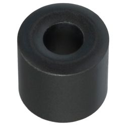
I tried it and didn't like the results, so I tried just one ferrite bead at one end, which sounded better. I then moved the bead up and down the length of cable and I found that I could tune the sound of the cable. Cool.
Another cable designer told me that he took RG59, 75-Ohm, coaxial cable with a copper shield and he used only the shield as a signal conductor!
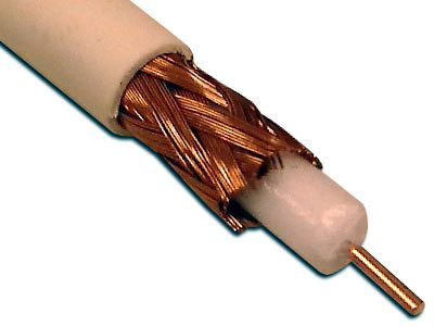
He used two cables per channel, one for the hot and one for the ground conductor. The truly interesting aspect of his design was that he applied a high voltage (+100Vdc) to the center conductor, which otherwise was unconnected. In other words, he created polarized cables. I tried his design and I found the sound a little too bright for my tastes, but I realized that he was on to something.
So I experimented on polarized cables for several years. I even mentioned them here long ago, back in 1999.
Still, as I saw it, there must be a better approach than just trial and error: there must a some sort of logic or geometry or topology to good cable design.
I was impressed with balanced XLR cables at the time and I found much to prefer over unbalanced RCA-terminated interconnects. Stop and think about the voltage relationships within an XLR cable: two anti-phase signal wires, one ground wire, and shield, which attaches to one chassis to another. In theory, no current flows through either the ground wire or the shield, as the two anti-phase signal wires complete a circuit within themselves. If the positive signal lead sees an instantaneous voltage of +1V, the negative signal lead must see an instantaneous voltage of -1V. If it doesn't, then it is not a balanced signal.
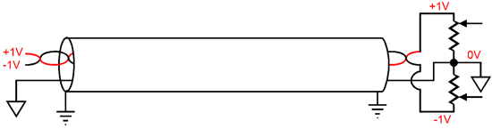
Ideally, there would be no voltage differential between either the two grounds or the two chassis, so there could be no current flow between the grounds or the chassis. This is not what happens with RCA-terminated unbalanced interconnects, as the shield conducts current, even if a separate ground wire is included.
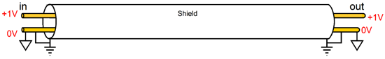
Note how the shield must carry current and how it connects the signal ground to the chassis ground. Also note how in the balanced XLR cable, the shield is neutral to both signal wires; or if you prefer, equally drags down both signal conductors via its capacitance to these wires. I wanted to make an RCA-terminated unbalanced interconnect that behaved more like a balanced XLR interconnect. Here was my solution: the shield no longer attached to both chassis; instead, it connected to a two-resistor voltage divider network that split the AC signal on the positive conductor and delivered it to the shield.
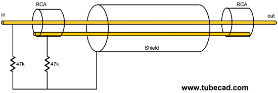
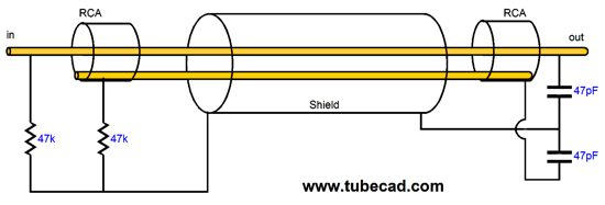
Thus was born my Broskie cable, which sounded quite fine. I used the Mogami cable and I was able to squeeze the two 1/8W resistors in the RCA plug's housing. A later development was the addition of two small-valued capacitors at the out end of the cable, which helped to prevent the shield from acting as an antenna.
I made this cable for friends and the most common complaint was that it cost too little (about $15 for a meter length) and everyone knew that the more you paid, the better it sounded. I also shared this design with a few cable manufacturers and it has been sold commercially, with neither profit nor credit to me.
Since I can never let any circuit be, to rest statically, I decided that I should try actively driving the shield.
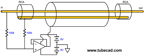
The two 100k resistors halve the output signal, which the OpAmp then drives the shield with this 50% signal. Thus, relative to either of the inner conductors, the positive and the ground, the shield is at 50% of its voltage value. Wait a minute; the ground conductor doesn't hold a voltage value. True enough, relative to the signal ground of the CD player or FM tuner or DAC or phono stage the ground conductor is an extension of ground, the circuit’s voltage reference. But relative to the shield, the ground conductor holds 50% of the peak-to-peak voltage between it and the hot conductor. Let's say that you discover a long length of interconnect that travels through your apartment ceiling. This cable intrigues you. You break out an oscilloscope and attach the ground lead to the shield, as you assume that it will be grounded somewhere. You then attach the probe to the two conductors within the cable. Two anti-phase voltage signals are present, so you conclude that the cable transfers a balanced signal. And, indeed, it does, relative to the shield.
I hated having to use two 9V batteries, as they are large and require a complex switch to power them on and off, so my next modification was to use only one battery.
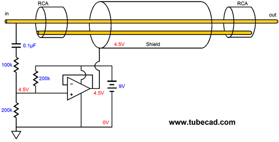
Where to start? First of all, I know that some readers believe that an OpAmp must have a positive and negative power supply, a bipolar power supply in other words. No so. The OpAmp needs to see a DC voltage across its power supply pins, but the power supply used can take many forms, as the following illustration shows.
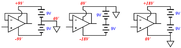
As far as the OpAmp is concerned, all three configurations are equal, as the OpAmp ’s power supply pins see an 18 volt voltage differential in all three setups. Okay, now we can move on to the 100k and 200k resistors. Both 200k resistors are effectively AC “grounded” at one end. Thus, in terms of AC signal, the two 200k resistors are in parallel with each other, so their combined resistance is 100k. So in terms of AC signal, the 100k resistor is in series with another 100k resistor, which defines a 50% voltage divider. In other words, the OpAmp will get half of the AC signal, with which it will then drive the shield. In terms of DC voltage, the two 200k resistors define a 50% voltage divider of the B+ voltage, which in this example is 9V, so 4.5V will appear at both the OpAmp’s input and output. Yes, the shield is slightly polarized, because of the +4.5Vdc present on it.
Mind you, +4.5Vdc is not a lot of voltage. If an external power supply, such as a medical-grade switcher desktop power supply, were used, then 15Vdc would appear at the OpAmp’s output with a 30V power supply. If unity-gain, high-voltage OpAmps were used, then even higher polarizing voltages could be obtained. Okay, how many readers know where I am going next?
Well, as this is the Tube CAD Journal, the obvious direction is towards the warm glow.
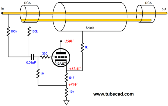
The 12AU7 functions as cathode follower that drives the shield via the 1k resistor, while also polarizing the shield to +52.5Vdc, which can be heard. The 0.1µF coupling capacitor relays the 50% of the AC signal to the 12AU7’s grid. The 517-ohm resistor biases the 12AU7 for 5mA of idle current flow. All in all, a sweet design. Once again, I have shared this design with many readers in e-mails and I know that at least one of whom is selling a driven interconnect based on my design (once again, neither for my profit nor credit).
Another configuration would be the following.
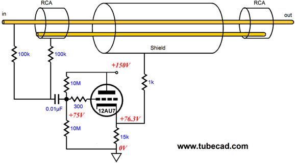
The two 10M resistors split the B+ voltage and single cathode resistor is used.
Of course, different tubes could be used. I would, however, stick to the 12AU7 or the 12AT7 or 5963 or 5965. Why? The 12V heater, which could be powered by a 12Vdc wallwart. But what about the +150Vdc B voltage? Ah yes, the B+ voltage could come from a DC-to-DC step-up power supply made by a friend of mine, who designs the electronic kits at LNS TECHNOLOGIES.
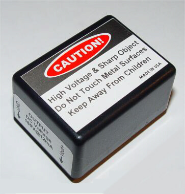
FEATURES:
Input Voltage: +11 to +26 VDC @330mA max
Output Voltage: +180 VDC @ 12mA (fully regulated)
Small volume: 1.5 x 2.0 x 1.0 inch
This is not a kit. It is fully assembled and tested under full load.
It comes with a data sheet and a sample application schematic.
This cute little module puts out +180V, which we can drop down to 150Vdc with a simple RC filter (3k resistor and 4.7µF capacitor). Because the intended customer is a normal electronics enthusiast, not an audiophile, the cost is only $25. Of course, if you insist on paying audiophile-worthy amounts of money, say at least $100, I don't think that John will complain too loudly ;) By the way, be sure to check out all the great kits, as they make perfect gifts for young (and old) electronic enthusiasts.
For tweaky, I should point out that since no cathode follower actually puts out unity gain, the actual gain being closer to 93% to 98%, depending on the triodes used. Thus, the AC signal voltage division should not be 50%, but a slightly higher ratio, i.e. 0.5/gain. In other words, the resistor that attaches to the signal hot must be slightly lower in value.
I will write about my experiments with speaker cables.