| John Broskie's Guide to Tube Circuit Analysis & Design |
28 May 2018 Post 426
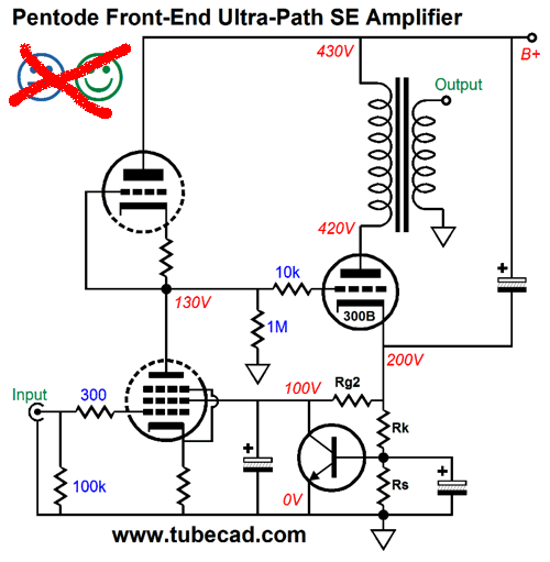
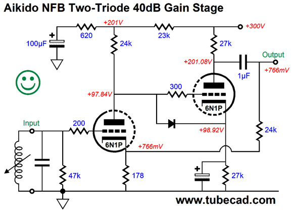
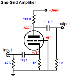
In my last post, I got my bottom electrolytic capacitors backwards—never a good idea. Thanks, once again, Merlin. Here is the corrected schematic.
The mistake was made easier to perform, asides from the dangers of cutting and pasting, as I had violated the rule I set forth in post 300:
I had ground potential at the middle and the bottom of the schematic; it should have appeared only near the center of the schematic. Next, we have a boo-boo from 2015, which a reader, Daniel, spotted. Thanks Daniel. It appeared in post 335.
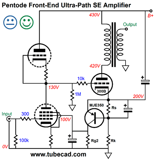
The NPN transistor doesn't work in an inverting mode relative to the 300B output tube. In contrast, a PNP transistor would deliver the required inverting DC signal, which would force the 300B into the desired idle current.
Imagine that the 300B is not conducting enough current to turn on the transistor, which would mean that the input pentode's screen (g2) would see 0V, which in turn would reduce the pentode's idle current flow, thereby allowing the triode-based active load to pull up the pentode's plate voltage, making the 300B see a more positive grid voltage, causing the 300B's current conduction to increase. If the 300B over shoots the desired idle current, the PNP transistor will turn on and pull up the screen voltage just to the point where the 300B current flow is sufficient to develop a voltage drop across resistor Rs equal to the MJE530's emitter-to-base voltage, about 0.6V to 0.7V, depending on the transistor's temperature. Note that the 300B's cathode is AC coupled the the B+ voltage through the electrolytic capacitor, making this an ultra-path design. It works due to the pentode input tube offering so poor a PSRR. In other words, both the 300B's grid and cathode will see most of the power-supply noise, so the 300B is effectively blind to the noise, which results in little noise-induced current variation in the 300B, which in turn results in no noise-generated current variation through the primary, so the secondary becomes blind to the power-supply noise as well.
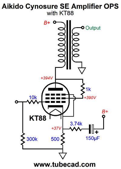
Aikido Cynosure SE OPS The first topology we need to look into more closely is the my almost 20-year-old variation on the Aikido cascade of two grounded-cathode amplifiers, which holds a seeming pointless resistor in series with the RC filter's capacitor.
The cynosure of this circuit is the added 620-ohm resistor. "Cynosure" is a lovely word, which means that person or object that serves as a focal point of attraction and admiration; it comes from the Greek word, kynosoura, that means dog's tail.
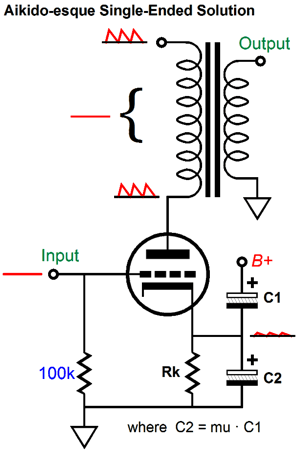
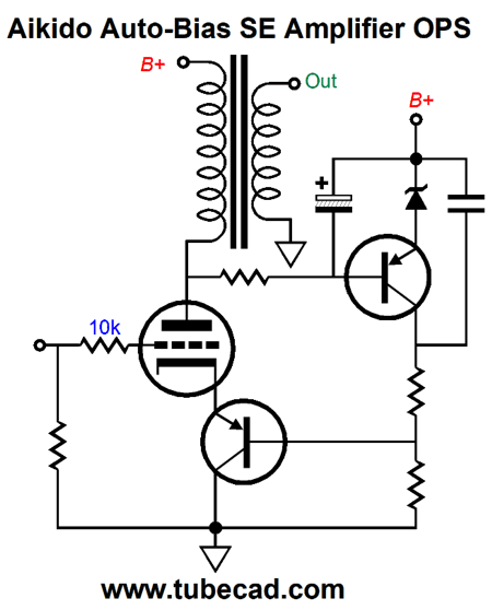
I like this word so much that I will use it as a label for a variation on the Aikido single-ended output stage. First, let's look at the original Aikido single-ended output stage:
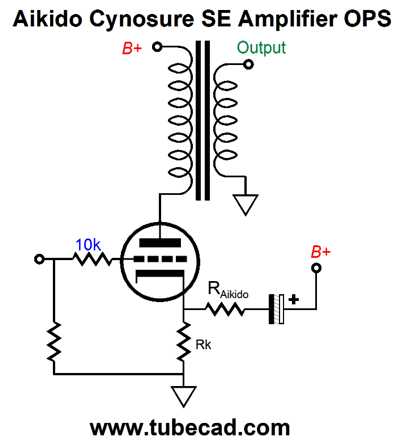
Our goal is not to eliminate the power-supply noise from the output tube's plate, but to ensure that 100% of that noise is present on the plate. No primary signal, no secondary signal. This setup works well, but it is a hassle to realize due to electrolytic capacitors being available in only a few values and being 20% tolerance parts. The Cynosure variation makes life easier, as a tail resistor is much easier to find in the desired value and in a tight tolerance.
The dog-tail resistor, labeled Raikido, injects just enough power-supply noise to null any variation in current flow due to the noise appearing at the plate.
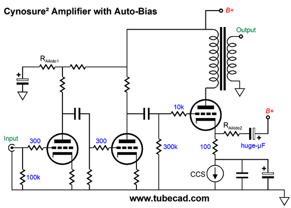
The 300B output tube idle at 75mA and the B+ voltage is 400Vdc, which implies that the transformer primary DCR is 80 ohms. Now, let's combine the Aikido cascaded front-end circuit with this output stage circuit, making for two tail resistors, or Cynosure squared.
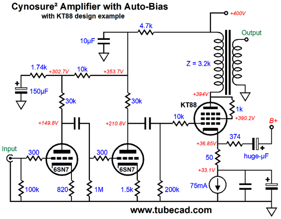
Both the front-end and the output stage sport an enhanced PSRR. The constant-current source auto-biases the output tube. Now, we will flesh out the topology with actual part values and voltages.
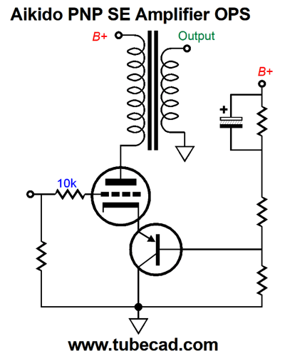
The problem with the 500-ohm cathode resistor was that it substantially reduced the KT88's transconductance and increased the output impedance at the 300B's plate. Note that the tail resistor terminates into a capacitor marked "huge-µF." In SPICE simulations, I found that 150µF was a good starting value. (I used a 1kµF capacitor to shunt the CCS.) The 6SN7 provides enough gain to easily drive the KT88 to full output with less than 1V of input signal. Before leaving this topic, I will show you yet another variation on the Aikido PNP SE Amplifier output stage.
The cathode resistor has been replaced by a PNP transistor. We can even add an auto-bias feature to the circuit above.
The top PNP transistor monitors the DC voltage drop across the primary's DCR, (with the zener diode working as a voltage reference) which will reveal the amount of current flowing through the output tube. The huge AC voltage swings are ignored, as the electrolytic capacitor shunts the AC signal away. If the tube draws too much current, the top transistor will increase its current conduction, which will pull up its collector voltage, which in turn will pull up the cathode voltage, causing the tube to decrease its conduction. The film capacitor relays the power-supply noise to the top of the two-resistor voltage divider that feeds the PNP transistor its signal. The problem we face with this last circuit is that PNP transistors stop at about -400V, such as the MJE5852G. The workaround might be to place a 300V zener across the PNP transistor or to place two PNP transistors in series (cascode).
Tube Current Mirrors
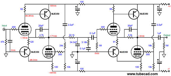
Above, we see two hybrid OpAmps with a passive RIAA EQ network in between. What is interesting is how the bottom triodes function as inverse current mirrors. But before going any further, we should go back to the tube-based current mirror.
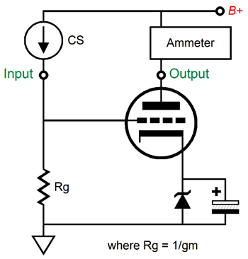
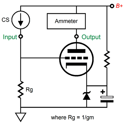
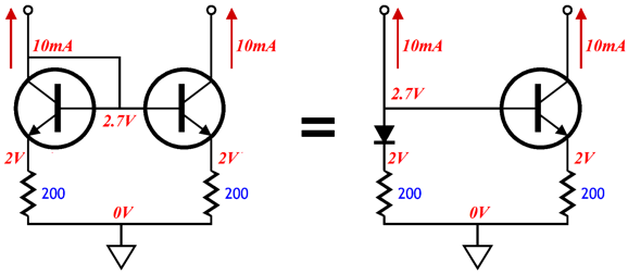
The bottom triode and its grid resistor define a current mirror, as long as Rc equals inverse of the bottom triode's transconductance. For example, if the triode's transconductance equals 10mA/V, then Rg must equal 1/0.01 or 100 ohms. In the schematic above, resistor Rg sees a current flow of 10mA and voltage drop of 1V. The bottom triode also sees a current draw of 10mA at idle. If resistor Rg sees an increase in current flow to 1.1mA, then the voltage drop across the resistor will climb to 1.1V, which the bottom triode will see as 0.1V increase in its grid voltage relative to its cathode, so it increases its current flow by 0.1V against 10mA/V, which will force its current conduction to increase by 1mA, bringing the total up to 11mA. In other words, the triode's current flow mirrors that which flows through resistor Rg. The zener diode used to cathode bias the bottom triode can be replaced by either a constant-current source or a lowly resistor, as the large bypass capacitor ensures that AC signals get current mirrored. If we desire DC current mirroring as well, then the following variation will keep the zener break voltage established, even if the triode is completely shut off for long periods.
The added resistor provides a current path for the zener up to the B+ voltage, so the zener's break voltage can be established without the triode's help. Okay, now let's compare the triode-based current mirror to the solid-state current mirror.
The two resistors marked R are equal in value. In the tube version, no cathode resistor was used. Why the difference? The triode offers so little transconductance that its wimpy transconductance works in place of a cathode resistor. For example, if the triode's gm is 10mA/V, then effectively the triode acts as if it offered infinite gm and held an internal cathode resistor equal the inverse of its gm, or 100 ohms. In contrast, transistors offer so much transconductance that the emitter resistor will overwhelm the inverse of the transistor's gm, which might be something like 0.001 ohms. By the way, the circuit above is rarely encountered, as two transistors are usually used instead.
The transistor on the left is effectively just a diode. Note how its base is tied to its collector. But as a diode it offers the same voltage drop that exists on the right transistor from its base to its emitter
So, the following two current mirrors are functionally the same. See post 246 for more information on current mirrors.
Okay, we finally have enough background information to move on to an inverting hybrid OpAmp.
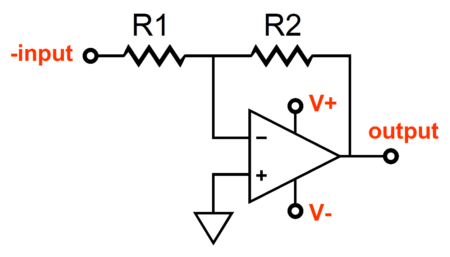
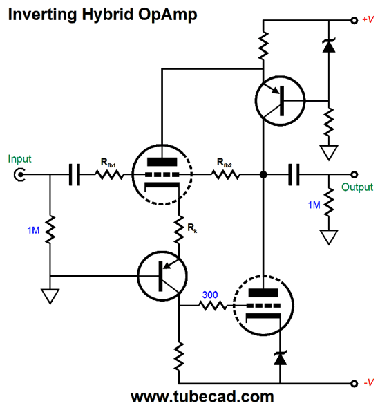
Inverting Hybrid OpAmp
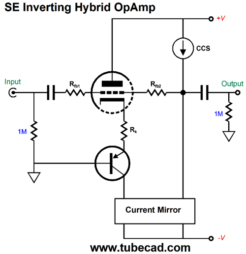
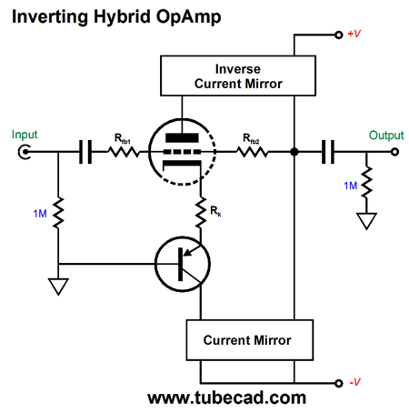
Making an inverting hybrid amplifier isn't that hard. The following design runs the output stage in single-ended class-A.
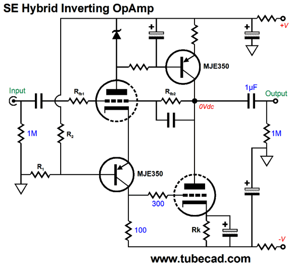
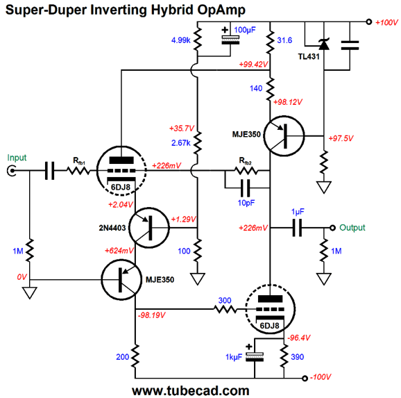
The triode operates in an inverting mode in this circuit, so resistors Rfb1 and Rfb2 set the feedback ratio and the gain. The current mirror will mirror the triode's current conduction, while the constant-current source loads the right output of the current mirror. Thus, if the triode increases its conduction due to a increase in grid voltage, the current mirror will pull down the output voltage. Conversely, if the triode lessons its current flow, the constant-current source will pull up the output voltage. What keeps the output from slamming from rail to rail is the negative feedback loop. Here is the topology fleshed out.
The top MJE350 is configured as a constant-current source, while the bottom MJE350 defines a bastode cascoding arrangement with the input triode. The bottom triode acts as a current mirror. In this example, we use the input triode's current flow to establish the zener's break voltage, but a resistor to ground or the negative power-supply rail voltage could be used instead. The assumption here is that a 6DJ8 tube will be used, which explains why a 100-ohm collector resistor is used in the current mirror. On the other hand, if we want anti or inverse current mirroring, we need to apply the bottom triode's input signal to its cathode, rather than its grid. Remember that in a grounded-grid amplifier, a positive pulse applied to the triode's cathode results in a positive voltage swing at its plate, due to the triode's current conduction dropping, as its grid has effectively become less positive relative to its cathode.
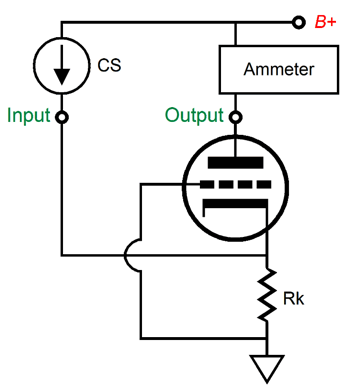
Converting a grounded-grid amplifier into an inverse current mirror is easy enough: we just make resistor Rg the triode's cathode resistor.
If we increase the constant-current source's current draw, the triode's cathode voltage will climb, so the triode's current conduction will fall. Conversely, a decrease in constant-current source current results in smaller cathode resistor voltage drop, which effectively makes the grid more positive relative to its cathode, so the triode's current conduction increases. This inverse current mirror topology can use other active devices, such as FETs, MOSFETs, and transistors. And since these devices all admit a P-version, we can place the inverse current mirror at the positive rail. Here is an example.
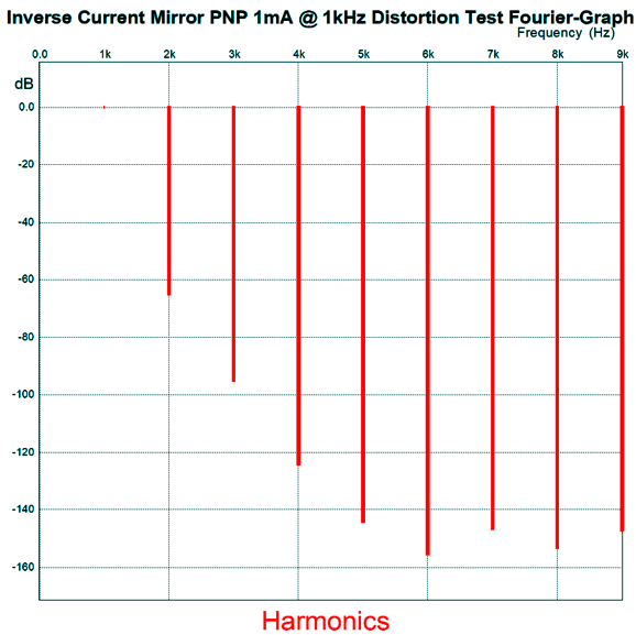
In this example, the PNP transistor's collector will anti mirror the triode's current conduction. I decided to test this circuit in SPICE and see how linear it was. I started with an idealized version, wherein the triode was replaced with a variable current source. The following graph shows the DC plot-line.
The current source's current is swept from 0mA to 20mA. Ideally, the plotline would extend from 0mA to 20mA. The next graph shows the Fourier breakdown of a 1mA AC current signal at 1kHz, with an idle current of 10mA for both the current source and the MJE350 transistor.
Not bad. But not that great. In fact, at 5mA of current swing, the distortion was far more noticeable. In other words, this circuit should be used within a global feedback loop. Here is one possible example.
Rather than run the output stage in single-ended, this output stage runs in push-pull.
As the both triodes conduct more, the top PNP transistor conducts less; as the both triodes conduct less, the top PNP transistor conducts more. Push-pull operation in a nutshell. Now, let's flesh out this design.
When I flesh out, I flesh out with gusto. Starting at the input triode, we see two PNP transistors used in a double cascode. The 2N4403 is a low-noise, low voltage PNP transistor. In this circuit, its base sees a portion of the power-supply noise, which will prompt an enhancement in the entire amplifier's PSRR. The top MJE350 PNP transistor sees a 140-ohm emitter resistor before encountering the shared 31.6-ohm. This split-emitter-resistor setup ensures equal/balanced current swings from the bottom triode and the PNP transistor above it. The TL431 is a shunt voltage reference, which works better than a zener, as it offers tighter tolerances and less noise. The input coupling capacitor is essential, as it allows 100% of the negative feedback to be used to center the output near ground potential. Note how all the active devices are DC coupled throughout.
Music Recommendations
I know about a fourth of them and I look forward to hearing the rest. Thanks Kerry.
//JRB
User Guides for GlassWare Software Since I am still getting e-mail asking how to buy these GlassWare software programs:
For those of you who still have old computers running Windows XP (32-bit) or any other Windows 32-bit OS, I have setup the download availability of my old old standards: Tube CAD, SE Amp CAD, and Audio Gadgets. The downloads are at the GlassWare-Yahoo store and the price is only $9.95 for each program. http://glass-ware.stores.yahoo.net/adsoffromgla.html So many have asked that I had to do it. WARNING: THESE THREE PROGRAMS WILL NOT RUN UNDER VISTA 64-Bit or WINDOWS 7 & 8 or any other 64-bit OS. One day, I do plan on remaking all of these programs into 64-bit versions, but it will be a huge ordeal, as programming requires vast chunks of noise-free time, something very rare with children running about. Ideally, I would love to come out with versions that run on iPads and Android-OS tablets.
//JRB |
John Says Thanks the Special 68 Only those who have produced a technical white paper or written an article on electronics know just how much time and effort is required to produce one of my posts, as novel circuits must be created, SPICE simulations must be run, schematics must be drawn, and thousands of words must be written.
If you have been reading my posts, you know that my lifetime goal is reaching post number one thousand. I have 574 more to go. My second goal is to gather 1,000 patrons. I have 932 patrons to go.
The Tube CAD Journal's first companion program, TCJ Filter Design lets you design a filter or crossover (passive, OpAmp or tube) without having to check out thick textbooks from the library and without having to breakout the scientific calculator. This program's goal is to provide a quick and easy display not only of the frequency response, but also of the resistor and capacitor values for a passive and active filters and crossovers. TCJ Filter Design is easy to use, but not lightweight, holding over 60 different filter topologies and up to four filter alignments: While the program's main concern is active filters, solid-state and tube, it also does passive filters. In fact, it can be used to calculate passive crossovers for use with speakers by entering 8 ohms as the terminating resistance. Click on the image below to see the full screen capture.
Tube crossovers are a major part of this program; both buffered and un-buffered tube based filters along with mono-polar and bipolar power supply topologies are covered. Available on a CD-ROM and a downloadable version (4 Megabytes). |
||


| www.tubecad.com Copyright © 1999-2018 GlassWare All Rights Reserved |