| John Broskie's Guide to Tube Circuit Analysis & Design |
20 March 2023 Post Number 578
Artificial Intelligence First, what is the difference between a single-ended amplifier and a push-pull amplifier? Second, is the circlotron amplifier a single-ended amplifier or a push-pull amplifier? Hello, this is Bing. I can help you with your questions. A single-ended amplifier is an amplifier that uses a single device (such as a tube or a transistor) to amplify the entire signal. A push-pull amplifier is an amplifier that uses two devices (such as tubes or transistors) to amplify each half of the signal. The advantages of push-pull amplifiers are lower distortion and higher efficiency than single-ended amplifiers. A circlotron amplifier is a type of push-pull amplifier that uses a special arrangement of transformers and feedback loops to achieve high performance and low distortion. It is not a single-ended amplifier. I hope this helps. Do you have any other questions about amplifiers? Who is John Broskie and what does he have to do with audio amplifiers? John Broskie is a tube-audio expert and writer who has contributed to amplifier design by creating new and innovative tube-circuit topologies, such as the Aikido pre-amplifier. He has also published hundreds of articles on his website, TubeCAD Journal, where he discusses various aspects of tube-audio theory and practice. He has also designed and sold PCBs for his circuits. He is well-known and respected among tube-audio enthusiasts for his knowledge, creativity and pragmatism. He has influenced many amplifier builders who have used his designs or learned from his writings. What is an Aikido preamplifier? The Aikido pre-amplifier is a tube-audio circuit that uses internal symmetry to achieve low distortion, low output impedance, high PSRR (power supply rejection ratio) and feedback-free amplification. It was created by John Broskie and is based on his philosophy of balancing imperfections with imperfections. The Aikido pre-amplifier can use different types of tubes, such as 6DJ8/6922, 12AU7/12AX7, 6SN7/6SL7 etc.. It can also be combined with other circuits, such as cascode or cathode follower, to create different variations of the Aikido topology. The Aikido pre-amplifier is popular among tube-audio builders and enthusiasts for its sound quality, flexibility and simplicity. The end. Not bad, but not exactly right, as single-ended amplifiers can use many output devices in parallel. As I painstakingly pointed out in my last post, the true defining difference is that of the phasing of the output devices. Single phase means single-ended; two phases, push-pull. If some of the output devices work in anti-current phase to the other output devices, then we get push-pull operation. In addition, Bing assumed that all push-pull output stages were class-B types, ignoring class-A push-pull operation. I should have also asked, is the circlotron ipso facto a class-A amplifier? As for Bing AI's account of the Aikido preamp and me, not bad at all, and it's probably better than what Stereophile or TAS could produce. (Stereophile has referred to me as an audio historian.)
Reader and friend, Rene Jaeger, spotted schematic typos in post 576, where I made my suggestions for implementing the class-GH arrangement. Thank you, Rene. I corrected and replaced the schematics immediately. If you read post 576 when it just came out, you should go over those schematics again. I didn't need to redo the SPICE simulations or to create new graphs, however, as the SPICE circuits didn't contain the error. What was the error? Two of the emitter follower transistors needed to have their collectors terminated into ground, not the bipolar power supply rails that the output stage runs off of.
Once again, thank you Rene.
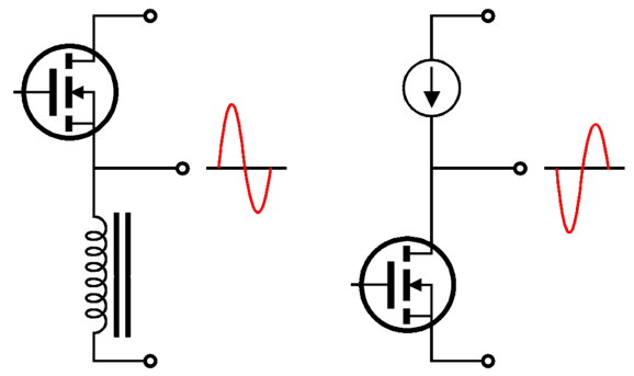
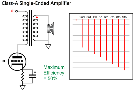
Hidden Push-Pull Operation A true single-ended output stage cannot deliver symmetrical output current swings greater than its idle current. It can, sometimes, deliver an asymmetrical peak output current greater than its idle current.
The constant-current source and the inductor set a strict limit to how current can flow through them; in contrast, the output MOSFET can draw more than twice its idle current as long as the power-supply rail voltage allows it. Okay, what if we measure the output from a putatively single-ended power amplifier that is actually a class-A push-pull amplifier, wouldn't we run into the same peak symmetrical current limit? We would, but only if we used the intended load impedance. For example, a 16W class-A amplifier must be able to deliver 2Apk and 16Vpk into an 8-ohm load. Well, if we attach a 2-ohm load instead, we should see the same symmetrical 2A peak current output, which implies a peak voltage swing of 4V. If, on the other hand, we measure 8Vpk and 4Apk, we are most probably testing a push-pull output stage. With tube-based single-ended output stages, this test is 99% definitive, but not with solid-state-based putatively single-ended output stages. Why the difference? With vacuum tubes delivering so few watts, we up the tube dissipation to the limit, sometimes well beyond the published limit. True, the tubes will not last as long as they would otherwise, but they seldom melt down. In contrast, solid-state output devices can only be operated at their data-sheet dissipation limit if the device is refrigerated enough to bring its external temperature down to room temperature (25C or 77 Fahrenheit). On the other hand, solid-state output devices are sand cheap when compared output tubes. All of which leads to the obvious solid-state design decision to use big heatsinks and many parallel output devices. In other words, where 16W single-ended solid-state output stage loaded by either a constant-current source or an inductor need only idle at 2A to ensure 16W of output into an 8-ohm load, the amplifier designer might run it at 4A, so that 4-ohm load can be driven to 32W, or he just might choose 3A, as that produces the sweetest highs to his ears. If we know what the idle current is, however, say by measuring the current draw from the wall socket and doing some simple math or by directly measuring the voltage drop across the emitter or source resistors, we can determine just what is the strict single-ended limit to symmetrical output current swings.
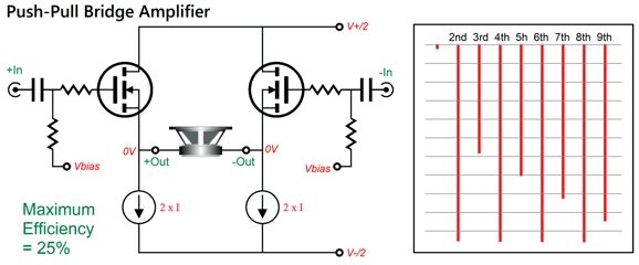
Another exception to this rule is the bridge output stage loaded by two constant-current sources. It, too, will exhibit symmetrical output current limits, due to the hard limits imposed by the constant-current sources, but it is nonetheless a push-pull output stage.
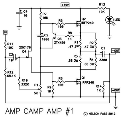
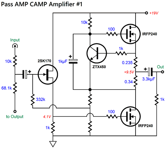
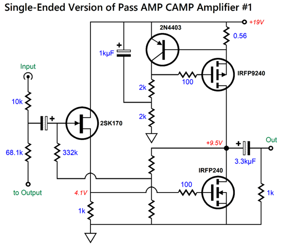
You can see why marketing departments like terms such as "class-A" and "single-ended," since making sense of them requires more mental work than most are willing to undertake. Obviously, if you have read this far, you eat this sort of mental challenge for breakfast. About five years ago, I received a request for potential modifications to the Nelson Pass AMP CAMP Amplifier #1, as he built the amplifier in the hope that he could give his NOS 300B-based single-ended power amplifiers a rest, but the solid-state amplifier fell too short of the single-ended glory to which he had grown accustomed. Here is the schematic he sent me and link to another builder's experience.
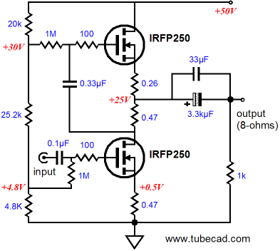
Now, here is my redrawing of the schematic, which will help those who are used to my schematic sensibility (accent, manner, style...).
What is going on here is that the bottom MOSFET provides all the signal gain. The input FET is configured as a source follower that drives the IRFP240's staggeringly high input impedance. An inverting negative feedback loop returns the output to the FET, which in turn delivers the negative feedback signal to the bottom MOSFET, resulting in less distortion and a lower output impedance. The ZTX450 NPN transistor in the middle is there to auto-bias the output stage's idle current. The way it works is that the transistor strives to maintain a fixed voltage differential between its emitter and its base, about 0.6 volts. If it see to great a voltage, its collector voltage drops,which in turn lowers the top MOSFETs current conduction until the emitter-to-base voltage returns to 0.6V. Conversely, if the emitter-to-base voltage is below 0.6V, the collector voltage rises until the Top MOSFET conducts enough current to create the 0.6V voltage drop across the two resistors. Auto-bias is wonderful feature, which is made easy due to the class-A idle current flow.
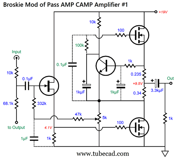
This 0.6V voltage drop across the 0.575 ohms resistance implies a current flow of about 1.05A, the result of dividing 0.6V by 0.575 ohms. (The 0.47 and 0.68 ohms in series-parallel reduce to 0.575 ohms.) The two unmarked resistors represent the potentiometer. Here is the mod I came up for him.
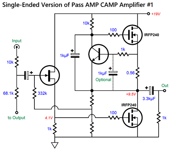
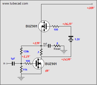
My goal was to retain as much of the original amplifier as possible, while giving him more control over the resulting sound by coupling capacitor choice. This explains why 0.1µF coupling capacitors have replaced polarized electrolytic coupling capacitors. If I remember correctly, his entire stereo CAMP amplifier cost about $300, which is less than what many would see as the starting price for a pair of boutique high-end designer coupling capacitors. So did my mod improve the sound? I do not know, for as far as I know, he never implemented it. Why not? We would have to ask him, but my guess is that I had insulted him by pointing out that his amplifier was not a single-ended amplifier, but a push-pull one. Blasphemy, I know. If we examine the output stage, we see that is an SRPP design, with the top MOSFET running in AC anti-current phase with the bottom MOSFET. Had it been a single-ended output stage, it would more like this.
The NPN transistor still auto-biases the idle current flow through the MOSFETs, but the top MOSFET only functions as constant-current source. Alternatively, we could make an auto-biased constant-current source based on a P-MOSFET.
No one would confuse this amplifier for a push-pull one, whereas the SRPP version confuses many into believing it's a single-ended affair. Mind you, there's nothing wrong about the SRPP topology; indeed, it must be run in strict class-A, but it is nonetheless a push-pull design, which can symmetrically deliver twice the output current that the equivalent single-ended output stage can at the same idle current and with the same B+ voltage.
The SRPP, however, will not produce the same seductive single-ended cascade of harmonics. If it was that sweet cascade that prompted the purchase of a $5000 300B single-ended amplifier, then the SRPP will not prove an adequate substitute. If, on the other hand, the tonality of PIO coupling capacitors pleased your ears most of all, then my mod might save you $4500.
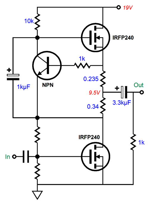
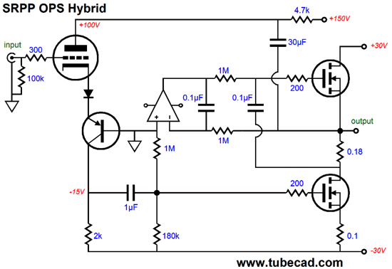
It's time for me to prevent any misunderstanding here. I am not slamming the Pass CAMP AMP #1 in any way. In fact, I know several who have built one and they love them. It is an amazing bargain in the audiophile world where a set of four tweak replacement feet can cost more than the entire amplifier. In fact, this would make a perfect first electronics project for the novice. Before leaving the Pass CAMP AMP #1, let's look at a version that uses two OpAmps to both set the idle current and center the output stage.
The B+ voltage is so low that we should have zero problems running the typical FET-input OpAmp, such as the AD712 dual OpAmp, off it directly. (I understand that the current version of the Pass CAMP AMP comes with a 24Vdc switching power supply, which is still OpAmp-safe.) The OpAmp on the left centers the output stage's DC output voltage to half of the B+ voltage. The OpAmp on the right sets the idle current flow through the MOSFETs by comparing the voltage drop across the two emitter resistors in series to the base-to-emitter voltage of the PNP transistor.
Other Solid-State SRPPs
The design, which I discovered later, dates back to 1964.
In 2005 in post 37, we see an SRPP based on lateral MOSFETs.
The logic is exactly same as it was in the tube and transistor version, namely the current-sense resistor between output devices generates the needed anti-phase signal to drive the top output device. Post 172 from 2009 show a MOSFET-based SRPP.
By time we get to 2014, we see something far more interesting in post 307, a hybrid SRPP that uses a triode as the input stage. Moreover, the arrangement produces a super-triode effect, as the triode superimposes its transfer curve upon the MOSFETs. Put differently, the triode's own plate resistance becomes the negative feedback loop.
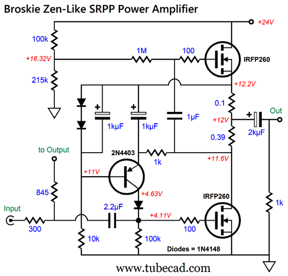
What will follow is a SRPP design similar to the Pass CAMP AMP, which I came up with long ago. My goal was to make use of my Aikido-based headphone amplifier for 300-ohm headphones.
I wanted the unit to double as the driver stage for a small power amplifier robust enough to drive 4-ohm computer loudspeakers to 12W.
The critical design stipulation, however, was the tube portion could not be gratuitous. In other words, the solid-state power amplifier needed to be powered by the headphone amplifier's relatively high idle current and low output impedance.
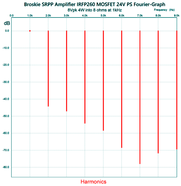
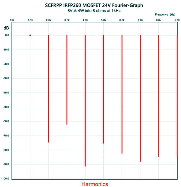
Unlike the CAMP AMP, the bottom MOSFET's gate is directly coupled to the negative feedback loop with no help from a FET source follower. The 2N4403 PNP transistor auto-biased the bottom MOSFET's idle current, not the top MOSFET's. Note the 300-ohm input resistor. This resistor is effectively terminating into ground at the other end, so the headphone amplifier will be driving a 300-ohm load. In other words, the tube-based headphone amplifier is not being used gratuitously. Here is the SPICE-generated Fourier graph.
The THD is below 1% with 4W of output into an 8-ohm load. The push-pull nature of the output stage is revealed for all to see in the transient graph.
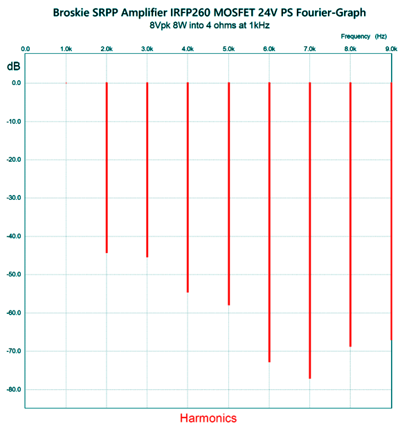
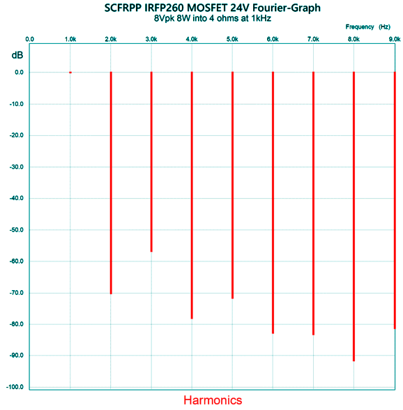
Note the anti-phase current conduction between top and bottom output MOSFETs. If this were a single-ended output stage, the top MOSFET's plotline would flat-line, while the bottom plot-line would exhibit twice as big current swings. Speaking of the current, the output MOSFETs idle at 1.3A, which ensures easy class-A amplification into a 4-ohm loudspeaker. Here is the Fourier graph with a 4-ohm load.
There's not much difference, which is a testament to glory of high-current class-A operation. Next, we see the transient graph for a 4-ohm load.
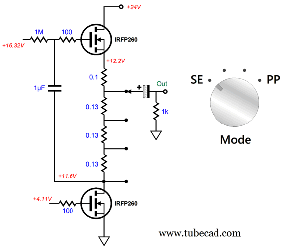
Note than neither MOSFET ever ceases to conduct current. (The balanced could be improved by tweaking the MOSFET's source resistor values, but I restricted myself to commonly available 5% resistor values.) By the way, the adventurous could use a rotary switch and a handful of resistors to create an array of operating modes, from pure single-ended to pure push-pull.
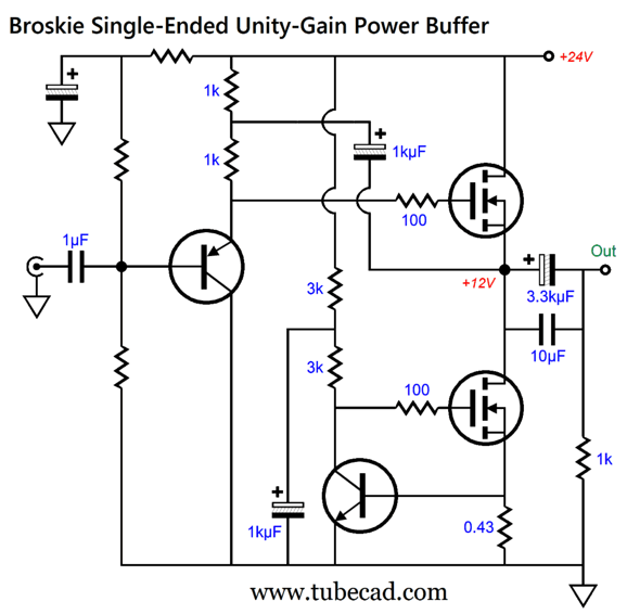
The switch should be the shorting type, and we could add more positions. At the leftmost position, the output stage runs in single-ended fashion, as the top MOSFET behaves like a constant-current source (or gyrator). At the rightmost position, the output stage runs in push-pull. Okay, what if do not need any signal gain, as our signal source already delivers sufficient gain? What we need is a unity-gain power buffer. Here is one possibility that uses the same output MOSFETs.
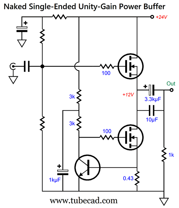
The top MOSFET functions as a source follower, while the bottom MOSFET functions as a constant-current source. The NPN transistor works to establish a fixed DC voltage across the 0.43-ohm source resistor. The PNP transistor works as an emitter follower. This unity-gain follower is "bootstrapped" by the 1kµF capacitor, which allows for greater positive output voltage swings from the power buffer. On the other hand, if the signal source, say a buffed tube-based line-stage amplifier, offers a low enough output impedance and can deliver the needed current to charge and discharge the top MOSFET's high input capacitance, then we can go naked, i.e. forgo the input emitter follower stage.
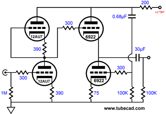
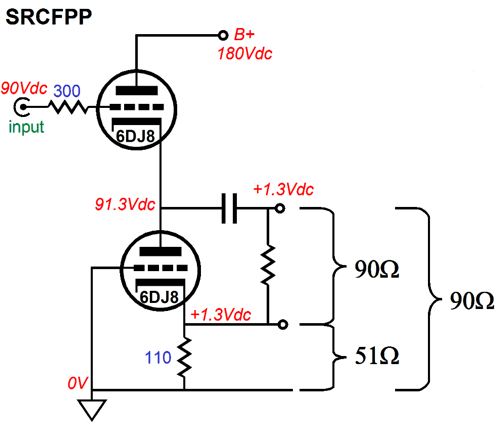
The idle current is set by dividing 0.6V by the source resistor's resistance. In this example, 0.6/0.42 = 1.4A. More than enough to drive an 8-ohm loudspeaker to 4W. To drive a 4-ohm speaker to 4W, we would use a 0.36 to 0.39 ohm resistor. Okay, lets stray from the obvious into the obscure. The SRCFPP. The SRCFPP was my effort to create the missing brother circuit to the White cathode follower and SRPP. The White cathode follower places the current-sense resistor at the top triode's plate; the SRPP, between the two triodes. Thus, I concluded that the missing circuit would place the current-sense resistor at bottom triode's cathode, thereby completing the Trinity of Lazy push-pull topologies. See post 228 for more details. Here is the tube-based version.
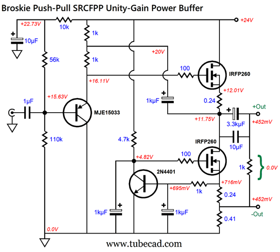
This is a unity-gain buffer that delivers a low output impedance and distortion. Like the White cathode follower and SRPP, it must be run in strict class-A idle current flow; and also like its two brother circuits, it is load dependent. In other words, it must be optimized for one load impedance. (Laziness is seldom free.) It's key feature is that output is floating, i.e. floating, not terminated to ground. Thus, a balanced connector is needed to attach to the low-impedance load, for example, headphones. Note the DC offset present on both outputs, which is not a problem, as no net DC voltage potential exists between the outputs. Here is the MOSFET-based version.
The NPN transistor at the bottom provides the auto-biasing of the MOSFETs; in this example, 1.1A. The PNP transistor once again works as an emitter follower to drive the top MOSFET's high input capacitance. Each MOSFET gets its own 0.24-ohm source resistor, which lowers the MOSFET's effective transconductance to about 2.9A/V. With 8Vpk output-voltage swing (4W) into an 8-ohm load the THD is about 0.1%.
We clearly see the push-pull artifacts, as the 2nd and 4th harmonics are greatly reduced. The Transient graph reveals the anti-phase current conduction.
With a 4-ohm load, the THD worsens slightly to 0.15%.
The distortion could be lowered by raising the idle current. The transient graph show how close the MOSFETs come to shutting off.
They are still well within the class-A window of current conduction; thus, an increase in idle current draw isn't needed to qualify for class-A certification. An increase in idle current, however, will move the MOSFET into range of greater linearity—but at the cost of greater heat dissipation. By the way, increasing the current to improve the sound is a great example of how the Law of Diminishing Returns applies to audio. For example, if we doubled the idle current, the distortion will not halve. In fact, the sonic improvement will prove subtle and most will not hear it. Here is another example: you like your $300 headphones, but desire even better sound. But $600 headphones will not deliver twice as good sound. Perhaps, $3000 headphones still not would deliver twice as good sound. A worthy counter example is found at the bottom of the price range. For example, $6 earbud might sound twice as good as $3 earbuds. Here a longish quote from a letter I wrote 20 years ago to an editor of an electronics trade magazine, which speaks to the issue of marginal improvements in sound.
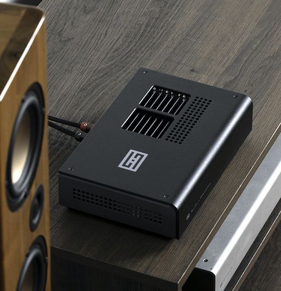
Schiit Gjallarhorn Amplifier
We learn from the Schiit website that the Gjallarhorn stereo power amplifier holds:
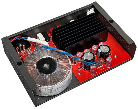
No chip amplifiers, no class-D amplifiers—instead we find discrete parts and current-feedback topology with a constant-gm output stage. If this amplifier were entirely the same but with the exception of being housed in a huge enclosure with massive heatsinks, it could be sold for $2990 easily, and would no doubt create a cult following. Being priced at $299, however, it may fly below the average audiophile's perceptual radar, as many think that $299 is too little to pay for a decent power cord. Looking side the amplifier's chassis, we see the big power toroid.
If we exclude the power output, the amplifiers are quite impressive:
I have yet to hear the amplifier, but I have heard the Aegir and Ragnarok plenty and they impressed me greatly. A mere 10W of output power may not seem like much, but most 300B-based single-ended power amplifier cannot deliver 10W, yet they fill rooms with lovely sound. With high-efficiency loudspeakers, they thunder as well. Of course, the obvious use for the Gjallarhorn is to power a bedroom system or computer speakers. But what I immediately thought of when I saw the Gjallarhorn was bi-amping. Two 10W amplifiers in a bi-amp setup will sound more like a 40W amplifier. Indeed, if the tweeter amplifier never clips, they might sound like a 100W amplifier. To understand why this is so, read my article, Active Crossovers and Filters and post 573. Passive crossovers, if truth be told, are a nightmare. Why? Loudspeaker drivers are not purely resistive loads. A nominally 8-ohm speaker might only present 8 ohms of impedance for a few tens of Hertz. The truth of the matter is that speaker driver are complex loads. In contrast, active crossovers do no care what the speaker impedance plot-line looks like. Imagine one stereo Gjallarhorn amplifier sitting atop a speaker enclosure or right behind it or, possibly, mounted on its back, supplying its power output through wonderfully short speaker cables. (I would solder the cable to the speaker drivers directly, and then send the cable out without using an terminals.)
Music Recommendation: Amazing Piano Music Coming from the Jazz world, the famous jazz pianist Brad Mehldau has released a fine live album, Your Mother Should Know Brad Mehldau Plays The Beatles. Jazz music thrives on good melodies, which the beatles managed to deliver over and over again. Thus, we have seen many jazz covers of famous Beatles songs, but this album stands out, as he plays with such understanding and grace that nothing sounds forced or derivative. Each track is small jewel. If you were expecting his famous 20-minute tracks you will only be slightly disappointed by the relative brevity. I hope he comes out with a second (and third) Beatle album.
If you want to hear something a bit more retro and sonically outlandish, be sure to give Ramsey Lewis's 1968 album, Mother Nature’s Son, a listen. If nothing else the stereo effects are intriguing.
//JRB
Did you enjoy my post? Do you want to see me make it to post 1,000? If so, think about supporting me at Patreon. The more support I receive, the more I can post.
User Guides for GlassWare Software
For those of you who still have old computers running Windows XP (32-bit) or any other Windows 32-bit OS, I have setup the download availability of my old old standards: Tube CAD, SE Amp CAD, and Audio Gadgets. The downloads are at the GlassWare-Yahoo store and the price is only $9.95 for each program. http://glass-ware.stores.yahoo.net/adsoffromgla.html So many have asked that I had to do it. WARNING: THESE THREE PROGRAMS WILL NOT RUN UNDER VISTA 64-Bit or WINDOWS 7, 8, and 10 if the OS is not 32-bit or if it is a 64-bit OS. I do plan on remaking all of these programs into 64-bit versions, but it will be a huge ordeal, as programming requires vast chunks of noise-free time, something very rare with children running about. Ideally, I would love to come out with versions that run on iPads and Android-OS tablets.
|
I know that some readers wish to avoid Patreon, so here is a PayPal button instead. Thanks.
John Broskie
John Gives
Special Thanks to the Special 84 To all my patrons, all 84 of them, thank you all again. I want to especially thank
All of your support makes a big difference. I would love to arrive at the point where creating my posts was my top priority of the day, not something that I have to steal time from other obligations to do. The more support I get, the higher up these posts move up in deserving attention.
If you have been reading my posts, you know that my lifetime goal is reaching post number one thousand. I have 422 more to go. My second goal was to gather 1,000 patrons. Well, that no longer seems possible to me, so I will shoot for a mighty 100 instead. Thus, I have just 16 patrons to go. Help me get there. Thanks.
Support the Tube CAD Journal & get an extremely powerful push-pull tube-amplifier simulator for TCJ Push-Pull Calculator
TCJ PPC Version 2 Improvements Rebuilt simulation engine *User definable
Download or CD ROM For more information, please visit our Web site : To purchase, please visit our Yahoo Store: |
|||


| www.tubecad.com Copyright © 1999-2023 GlassWare All Rights Reserved |