| John Broskie's Guide to Tube Circuit Analysis & Design |
20 February 2023 Post Number 576
"The best way to predict the future
The Amplifier of the Future A safe start to our predictions, however, is to begin with the primary assumption that we want it all. We want the best sound possible, the highest efficiency, the smallest size, and the lowest price. Thus, we can reasonably assume that 300B and 845 output tubes, sadly, are not invited to this future party. In addition, we can assume that digital signal sources are not going to disappear, in spite of the recent resurrection of LPs and open-real tape. (Indeed, the phono cartridge's or the tape-head's tiny output signal can be run through an analog-to-digital converter [ADC], whose digital signal can receive RIAA or NAB equalization in the digital domain.) Another safe assumption is that streaming is here to stay, whether it is by WiFi, Bluetooth, or 5G. Wires suck. The less wire, the better. As I put in post 242:
Another assumption is that nothing beats class-A (preferably single-ended) amplification, with the further built-in assumption that the single-ended amplifier does not face a output-power limit; in other words, we are not limited to 8W single-ended amplifiers and that a 1kW single-ended amplifier would sound better than any 1kW class-B, class-AB or class-D amplifier. Another safe bet is that switching power supplies are the future. Other than toasters, power tools, refrigerators, and audio gear, what electric devices sold today do not sport an internal switching power supply or a USB socket? (About ten years ago, a friend built a solid-state power amplifier that held a conventional power supply that powered the input and VAS stages, but used four switching power supplies to power the two output stages, with each channel getting two, thereby making a bipolar power supply with the 48Vdc switching power supplies. The enclosure's small size forced this arrangement on him, as he would have preferred to use a huge toroid transformer, leaving the Chinese-made switching power supplies behind. Having built the amplifier, he found himself pleasantly surprised that the switching power supplies didn't seem to hurt the resulting sound; indeed, their built-in current limiting sidestepped burnt output devices when the amplifier's output accidentally shorted.)
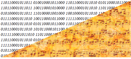
My first prediction is that we will soon have power amplifiers that only accept digital signals, with perhaps some additional and begrudging acceptance of an analog input signal that must travel through an internal ADC before the amplifier sees it. This means that the amplifier must hold its own internal DAC, as the power amplifier's output stage will remain an analog affair, not a digital one. What! Why do we need to go through the digital domain at all? Turning analog signal into digital signal offers too many advantages to forgo. For example, we can easily impose a time delay on the digital stream of data. In addition, we can digitally attenuate, amplify, and equalize the digital signal; and in addition, we can stream the data through the air. Most importantly, digital music files are effectively dead, unlike analog music sources, such as LPs, microphones, and tape. Once a musical performance is transcribed into a digital file, surprises are no longer possible, unlike an LP no additional random tick or pops are possible; what digital music file presently holds is all that it can ever hold, which just might include preexisting ticks and pops in the recording.
Moreover, we can examine the digital data and quickly find the peak output and the steepest climb up from quiet to loud. In other words, since we can entirely know the past incased in the digital file, we also know the future playback perfectly. What could prove more valuable than knowing the future perfectly? Imagine if you went to Las Vegas and knew the result of every roulette wheel spin before it happened! Or, imagine that before going out on that first date, you knew of the impending emotional tragedy waiting for you two years later. Once the future is known, we can proceed to anticipate and plan on what the amplifier must deliver. Imagine that you summon your favorite performance of Beethoven's 5th Symphony (mine remains Carlos Kleiber's 1975 recording on DG). The digital file is quickly read in its entirety, so all the expected crescendo demands on the power amplifier's output are known and factored in calculations with your power amplifier's peak output potential and the present volume setting. (Or, as I have mentioned here before, the digital music file's header can contain the outline of signal amplitude over time, so the file no longer needs to be read in its entirety, but can be read as it is played.) For example, if the known and expected peak crescendo exceeds your amplifier's potential power output, a red indicator light will shine below your volume-control knob (if you are retro inclined, or a red indicator will light up on the pixel display of your choice), warning you of the impending clipping. Thus, you would turn down the volume until the red light turned off; or, you might opt to let the power amplifier apply a soft-clipping function in the digital domain, which would round and compress the peak signal, so the amplifier never actually clips.
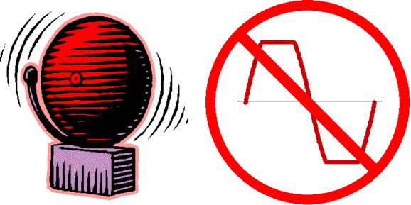
Eliminating clipping is a huge feature, for it not only sounds better but it also protects delicate tweeters. Most importantly, as the performance proceeds, the analog power amplifier's power-supply-rail voltages swell and collapse as needed for the output stage to deliver the required peak voltage and current swings into the loudspeaker.
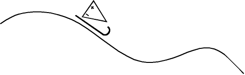
Yes, this is my idea of sledding-bias all over again, but expanded to include expanding and contracting power-supply-rail voltages, along with an added subtlety: a multiplying DAC (MDAC). The MDAC has made an appearance here before. In fact, here is a longish quote from post 407:
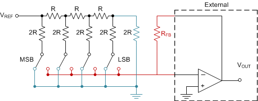
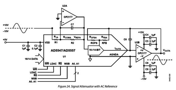
So far, the assumption has been that only a positive DC reference voltage enters the MDAC, but we can use a negative DC voltage with many MDACs. In fact, such an MDAC works as super-fancy stepped attenuator, with super-fine and super-precise decrements, by feeding AC signal instead of DC voltage. Here is an example circuit from the AD5547 MDAC data sheet.
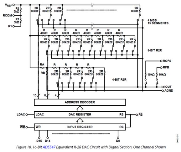
Note that the input signal swings both positively and negatively. How's that possible. Inside the MDAC is a bunch of resistors arrayed in an R-2R arrangement, with each resistor terminating into a switch. In other words, as long as the resistors and switches do not burn out, they do not care if the reference voltage is DC or AC, positive or negative.
Okay, let me add that most current-production MDACs top out at +/-15V of analog voltage input, but the AD5547 can withstand +/-18Vpk. What if new MDACs were made that could handle far more voltage say +/-50V or even +/-100V? Well for one, we could forgo requiring the analog power amplifier to provide any actual voltage amplification, as the MDAC's output voltage wouldn't need any amplification. (The assumption here is that the MDAC would contain an I-to-V converter stage at its output.) Imagine we feed +/-42V of DC into the MDAC as its reference voltage and then let the MDAC do the conversion of digital ones and zeros into analog output voltage that could peak at +/-40Vpk, which translates into 100W into an 8-ohm loudspeaker. The MDAC would not drive the loudspeaker directly, as a unity-gain power buffer would, whose own bipolar power supply rail voltages would have to be something like +/-45Vdc to sustain 100W of output. In order to gain much greater efficiency, we vary the buffer's rail voltages dynamically. At idle, the speaker -driving, class-A single-ended power buffer might see bipolar power-supply-rail voltages of only +/-5Vdc, but it would idle at 5A. With such low rail voltages, we would be lucky to get 1W of output, but the 5A of idle current would allow up to 100W of output with the +/-45Vdc rail voltages. If we add a dynamically varying idle current to the mix, the efficiency would climb up to class-D amplifier levels, but the sound would be single-ended class-A amplifier quality.
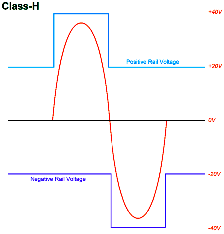
Understand, dear reader, that this arrangement is only possible because the digital music file is lifeless; much in the same way that book of poetry is dead, as the printed words won't and can't change. (Their meanings might over time, but the inked letters remain constant.) So what we have is a digital file, an MDAC, a unity-gain power buffer, and sonic glory. Neither line-stage amplifier nor power amplifier nor interconnects were needed. If an MDAC and a power buffer were housed in each loudspeaker, no speaker cables would be needed. What if the signal source wasn't some digital file stored on a hard-drive, but a digital stream, possibly of a live event. In other words, what is the signal wasn't lifeless, but living, capable of unexpected change? The workaround would be to apply a small time delay say 10 seconds or so. The delayed and stored data stream would be analyzed to figure out the needed power-supply rail voltages and bias current flow. The big limitation would be the amount of time required to swell or collapse the bipolar power-supply voltages. We wouldn't want to run into a severe form of slew-rate limiting, wherein the rail voltage could not be increased quickly enough to accommodate the upcoming crescendo. In contrast, a slow decrease of the signal level is less of a problem, as we only waste heat, but hear no clipping. Another possible arrangement would be to forgo the use of a switching power supply with a quickly-varying output voltage, but use a multi-voltage conventional power supply instead. For example, the bipolar power supply might offer +/-12Vdc, +/-24Vdc, +/-36Vdc, and +/-48Vdc voltage outputs. The power buffer would then receive a four-step class-H switching of rail voltages.
Think of it as a coarse (or pixilated) blending of class-G and class-H amplifiers. With soft background music playing, the power buffer would run entirely off the +/-12Vdc power-supply taps. As the volume increases, higher rail voltages would switch in an out. The result would not be as efficient as the sledding power-supply version, but it might be easier to implement. This leads us to the next topic.
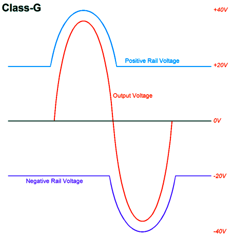
Class-G/H Amplifier
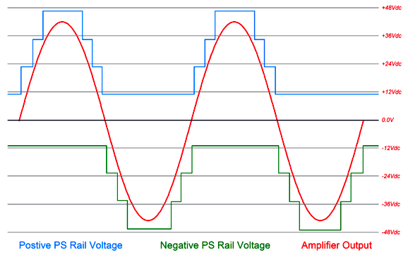
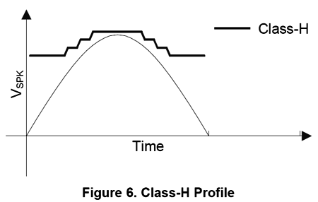
I call the amplifier on the top class-G; the other class-H. Others do just the opposite. In Bryson's Texas Instrument application-report, we see a blending of the two classes of operation. Instead of the single square-wave slamming on of the higher rail voltages or the gentle hugging climb to high voltages, we see a staircase series of rail-voltage jumps. Class-GH amplifier is a good name for this approach, as no matter which side you fall on in the class-G-and-class-H classification debate you get what you believe. Here is an image from the Bryson's report:
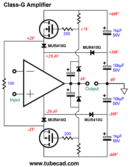
All of this got me thinking about how implement the class-GH arrangement on a big power amplifier. My first thought that was that it should be similar to the cascode arrangement, wherein the N-output devices get N-switching devices, either NPN transistors or N-channel MOSFETs, while the P-output devices get P switching devices, either PNP transistors or P-channel MOSFETs.
A few seconds of reflection revealed that this was not the way to go, as top-level switchers would never yield their maximum output voltage. In other words, the N-output devices must get P-switching devices, either PNP transistors or P-channel MOSFETs, while the P-output devices must get N-switching devices, either NPN transistors or N-channel MOSFETs. When bigger output voltage swing is required, the power-supply rail voltages are boosted as needed by switching on the high rail voltages. Just how to make the switching happen is what intrigued me. The class-G amplifier arrangement of capacitor-bypassed zeners attached to the output will not cut it.
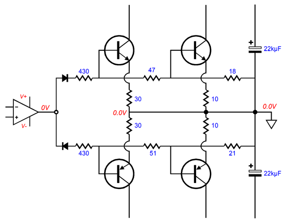
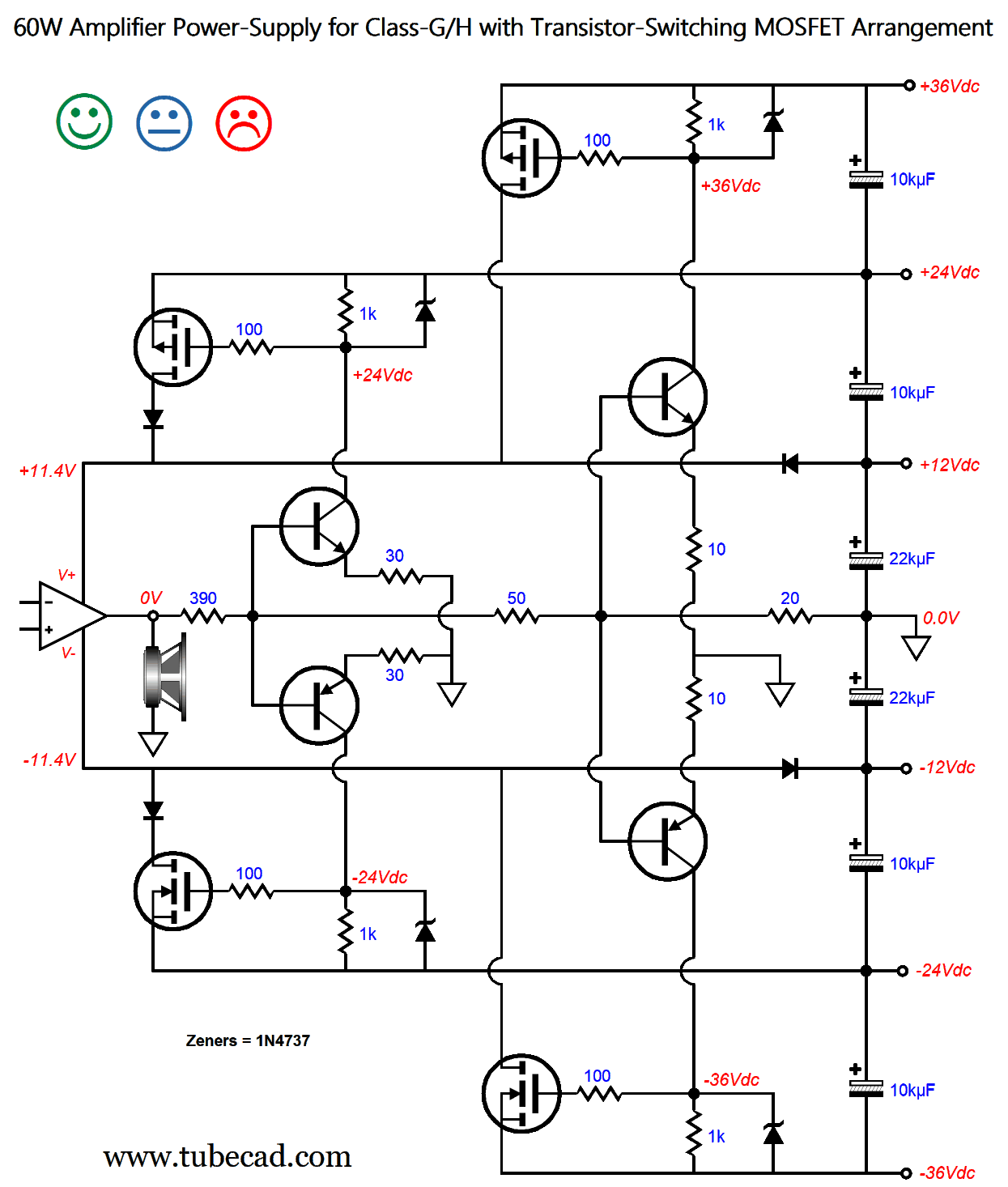
Yet, the rising amplifier output voltage must trigger the switching action. Here is my solution.
The power amplifier's output stage must drive both the loudspeaker and a 490-ohm load made up of 3 resistors in series, 430, 36, and 24 ohms. This resistor string defines a three-resistor voltage divider. If the amplifier output reached 49Vpk, the voltage division would result in 46V, 6V, and 2.4V voltages. With the maximum bipolar power-supply-rail voltages of +/-36Vdc, we can expect a maximum amplifier output-voltage swing of 32Vpk, which translates into 64W into 8-ohm loudspeakers. The resulting voltage division would be 32V, 3.9V, and 1.6V. By altering the resistor values, we can alter the voltage divisions and, in turn, the switching of the transistors. A bipolar transistor typically needs a base voltage between 0.5V to 0.7V for the transistor to turn on. Transistors make great switches, sharply turning on and off, which explains why they are used in computer CPUs and DACs. (Because the transistors do make such great switches, the 10-ohm and 30-ohm emitter resistors are there to limit the transistor current flow.) Of course, we could use two three-resistor voltage dividers, one for the NPN transistors and one for the PNP transistors, which would allow us to tweak the turn-on timings.
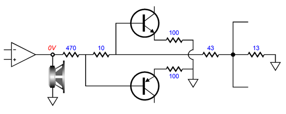
Another way we can tweak the timing of the MOSFET switching on is to add a resistor or two to the single resistor string.
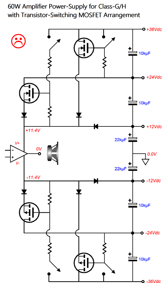
With this arrangement, the bottom N-MOSFET will turn on slightly ahead of the top P-MOSFET. At idle and at low power-output levels, the output stage sees only the 11.4Vdc bipolar power-supply rail voltages.
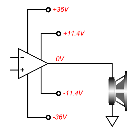
The power amplifier's input stage and VAS stage, on the other hand, see a fixed +/-36Vdc bipolar power-supply rail voltages. As the amplifier's output voltage climbs, the pair of transistors on the left turn on first, then with further increased voltage swing, the pair on the right turns on.
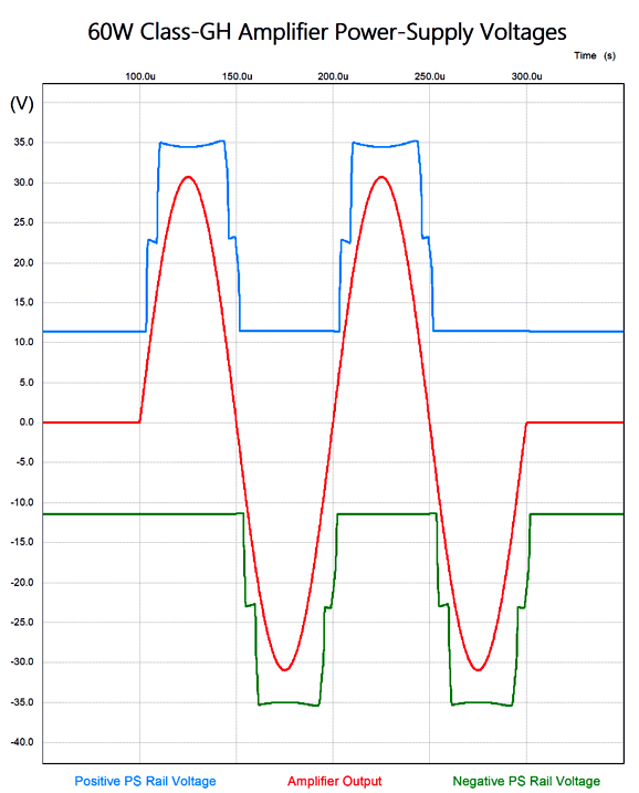
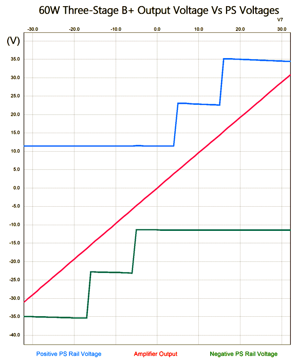
Note that, at idle, all the transistors and MOSFETs are turned off. The zeners limit the maximum MOSFET gate voltage. In SPICE simulations, this arrangement worked well, as the following SPICE-generated graph shows.
(I love two-cycle tone bursts, as they can reveal problems that steady sinewaves hide.) The amplifier output voltage is +/-32Vpk at 10kHz, which translates into 64W. The following is a graph of the power-supply voltages delivered to the output stage while it drives an 8-ohm load.
The sag is due to the MOSFET's Rds resistance against the current draw. The SPICE model I used for the N-channel MOSFETs was that of the IRFP240, which is long in the tooth, as is betrayed by its relatively high Rds of 0.18 ohms. The newer IRFP260 offers a much lower Rds of only 0.04 ohms. Returning to the schematic, this was my first draft, which explains the three faces. If this power amplifier only powered a subwoofer, then the happy face applies. On the other hand, I fear that the switching on of the MOSFETs would not be fast enough at the other end of the audio spectrum, due to the MOSFET's high input capacitance. This becomes a much bigger issue with higher power output and higher frequencies. The last thing we want to do is inadvertently to build in slew limiting. One workaround would be to include emitter followers to drive the MOSFET's gates.
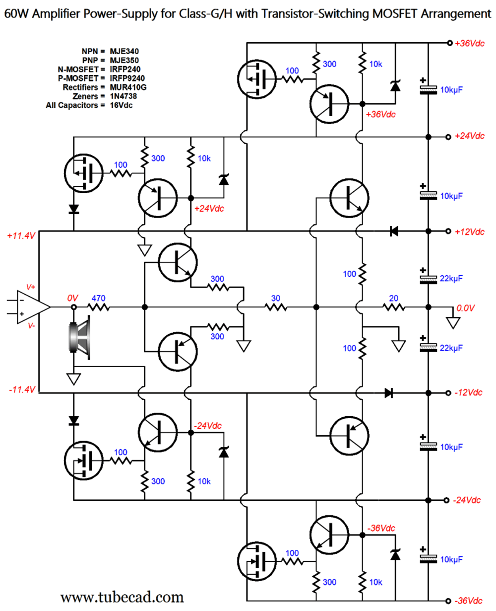
The emitter followers not only allow greater current delivery, as their relatively low-ohmage emitter resistors provide a faster discharge path for the MOSFET input capacitance. The zeners both limit the on-voltage the MOSFETs and protect the emitter-follower transistors from excessive emitter-to-base voltages. Okay, let's add this enhancement to the class-GH amplifier.
Click on schematic to see enlargement No doubt, few solid-state-loving audiophiles would regard 60W as a lot of power. But even fewer would view 60W of class-A output as trivial. With the fantastically reduced power-supply rail voltages of only +/-11.4Vdc at idle, we can run a fabulously rich idle current flow that would ensure class-A output at full power, yet run relatively cool. How cool? A conventional class-A, push-pull power amplifier that delivered 60W of output must dissipate at least 120W at idle, as the maximum theoretical efficiency is 50%. This amplifier, in contrast, would dissipate only 44W at idle, bringing its efficiency to 74%, which is dang close to the 78% of a class-B amplifier. Okay, what if we want more watts? We need only up the rail voltages.
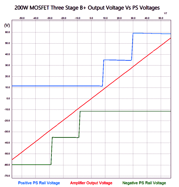
The same reduced power-supply rail voltages of only +/-11.4Vdc appear at idle, but the +/-48Vdc rail voltages kick in when the amplifier delivers 100W. What? You want even more power?
Now, the output stage (OPS) gets +/-60Vdc when needed. By the way, we could have added additional step voltage, which would improve efficiency and lower the needed capacitor voltages. As you can see, the sky is the limit, as we could go all the way up to +/-100Vdc power-supply rail voltages, which would allow over 500W of power delivery into an 8-ohm speaker. How well did the 200W version work in SPICE simulations? Very well indeed.
The stepped power-supply rail voltages tracked the two-cycle tone burst nicely. Here is a close-up of the first transitions.
It's still hard to see, but there's plenty of headroom for the OPS.
The amplifier's output voltage triggers the first switching at about +/-8Vpk and the second at about 28Vpk.
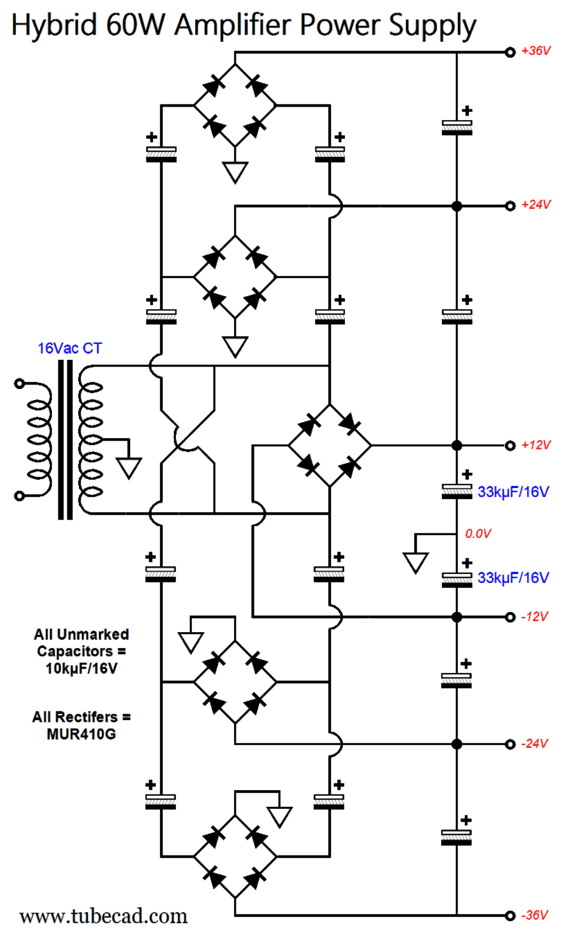
Power-Supplies for Class-GH Power Amplifiers Nor are we forced to use multiple power transformers, as a single power transformer can hold many taps on its primary. (I used to own huge 500VA power transformers that offered about a dozen primary taps, each about 20V greater than the previous. Why was it designed this way? They were part of a high-voltage regulator that strove to maintain a fixed and limited voltage across the output pass device. In other words, as a high output voltage was required, the next higher primary tap was selected. When we moved from California, they remained behind, sadly.)
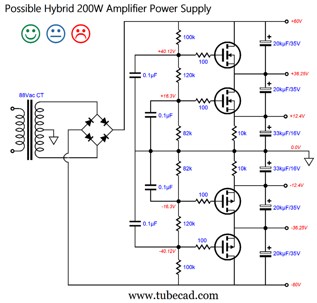
Here we see a single center-tapped primary and five bridge-rectifiers deliver three bipolar power-supply voltages, 12Vdc, 24Vdc, and 36Vdc. Note that all the capacitors used are only rated for 16V, in spite of the 24V and 36V rail voltages. The center capacitors are larger in capacitance than the other capacitors, based on the assumption that they will get continuous depletion, both at idle and with normal music playback. If driving a shaker-table or producing sustained full-output sinewaves is the goal, then all the capacitors should be equal in capacitance. I wonder if something simpler wouldn't work. If we operate under the assumption that musical content offers a wide dynamic range, with few peak demands on the power supply, then the following design might work.
The amplifier's output stage cannot idle at class-A current flows, as all the MOSFETs deliver current at idle, so class-B idle current should be allowed. It's only at the output swings big do they get some relief. In other words, the goal here is not greater efficiency, but possibly better sonic performance and reduced heat dissipation of the output stage devices. Note that the MOSFETs work as capacitance-multiplier circuits, as their output voltage resembles that of a voltage regulator, at least in terms of ripple rejection, not so much in terms of fixed output voltage. My guess is that this design is either really bad or really good. (It would be great to experiment on it with real music playback, not sine-wave generators.) Another design idea I had was that we might use two power transformers and then mix full-wave rectification with half-wave rectification.
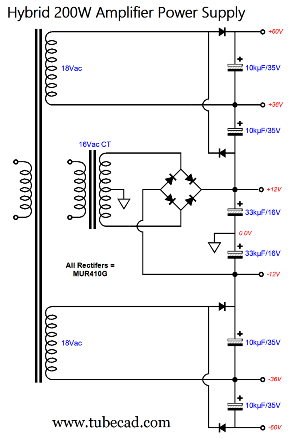
The +/-12Vdc and +/-60Vdc power-supply rails get the full-wave treatment, but the +/-36Vdc rails only get half-wave rectification. Note how few rectifiers are needed to produce three power-supply rail voltages. Also note the 24V jump from 12V to 36V and from 36V to 60V. By the way, we can create dissimilar voltage jumps with the single center-tapped secondary.
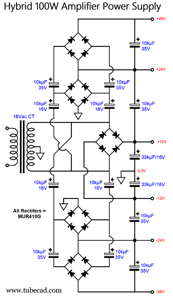
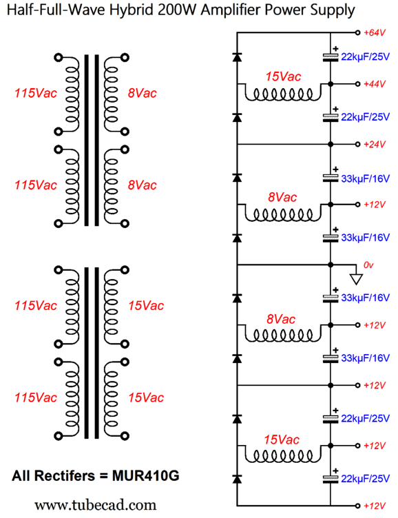
The bipolar power-supply-rail voltages go from 12V to 24V and, then, to 48V, not 36V. The only difference is where the top and bottom bridge rectifiers are terminated. Okay, let's return to the half-full-wave rectifier power-supply circuit. With just eight rectifiers, we can make a four-voltage bipolar power supply.
Two power transformers are shown, but we could have also used a single power transformer with four secondary windings. I ran SPICE simulations with unnaturally small-valued capacitors to better show the ripple shape.
We see that the 24Vdc and 64Vdc rail voltages put out full-wave ripple (120Hz), while the 12Vdc rail puts out half-wave ripple (60Hz). The 44Vdc rail puts out a blend of the two ripples.
Music Recommendation: Beethoven, Révolution, Symphonies
Admittedly, the 3rd and 7th sound a bit anemic compared to the big-German sound we grew up hearing. But then, would Beethoven approve of the big, heavy Germanic sound? Perhaps not.
Qobuz beats Amazon this time, as they offer the recording in glorious 24-bit, 88.2kHz high-res format. //JRB
Did you enjoy my post? Do you want to see me make it to post 1,000? If so, think about supporting me at Patreon.
User Guides for GlassWare Software
For those of you who still have old computers running Windows XP (32-bit) or any other Windows 32-bit OS, I have setup the download availability of my old old standards: Tube CAD, SE Amp CAD, and Audio Gadgets. The downloads are at the GlassWare-Yahoo store and the price is only $9.95 for each program. http://glass-ware.stores.yahoo.net/adsoffromgla.html So many have asked that I had to do it. WARNING: THESE THREE PROGRAMS WILL NOT RUN UNDER VISTA 64-Bit or WINDOWS 7, 8, and 10 if the OS is not 32-bit or if it is a 64-bit OS. I do plan on remaking all of these programs into 64-bit versions, but it will be a huge ordeal, as programming requires vast chunks of noise-free time, something very rare with children running about. Ideally, I would love to come out with versions that run on iPads and Android-OS tablets.
|
I know that some readers wish to avoid Patreon, so here is a PayPal button instead. Thanks.
John Broskie
John Gives
Special Thanks to the Special 79 To all my patrons, all 79 of them, thank you all again. I want to especially thank
All of your support makes a big difference. I would love to arrive at the point where creating my posts was my top priority of the day, not something that I have to steal time from other obligations to do. The more support I get, the higher up these posts move up in deserving attention.
If you have been reading my posts, you know that my lifetime goal is reaching post number one thousand. I have 430 more to go. My second goal was to gather 1,000 patrons. Well, that no longer seems possible to me, so I will shoot for a mighty 100 instead. Thus, I have just 21 patrons to go. Help me get there. Thanks.
Only $12.95 TCJ My-Stock DB
Version 2 Improvements *User definable Download for www.glass-ware.com
|
|||


| www.tubecad.com Copyright © 1999-2023 GlassWare All Rights Reserved |