| John Broskie's Guide to Tube Circuit Analysis & Design |
Post 228 28 April 2012
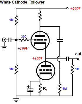
SRCFPP Let’s pull way back and survey just what our common goal is with these two famous circuits. It is not tone or stereo imaging or bass slam or liquid mids or velvet highs. No, our goal is simply the push-pull operation of two triodes—but on the cheap, as we will only supply an unbalanced input signal, not a balanced, push-pull set of signals. In other words, these two famous two-triode, push-pull circuits do not require an external phase splitter, as they generate their own complementary, balancing anti-phase signal. Here is where the label "reflexive" come into play in SRPP and SRCFPP, as reflexive means to direct back on itself and to elicit automatically, as these circuits intrinsically create their own anti-phase signal as result of the input signal and the resulting current variation through the load resistance and a current-sense resistor, which produces the needed anti-phase signal. Here is where "series" enters the description, as the current-sense resistor, Rs, lies in the same current path as the load. In a White cathode follower, the sense resistor is located at the top of the circuit, at the top triode's plate.
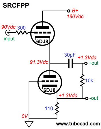
The problem with the above schematic is that it does not include the external load resistance, which is essential to understanding how the push-pull operation obtains. So, it’s up to you to imagine a low-impedance load, say 100 ohms. If this 100-ohm load resistance sees a 1V positive pulse across it, a peak current flow of 1V/100-ohms, or 10mA, is created. This 10mA pulse will provoke a voltage pulse equal to 10mA against the series resistor Rs, which then becomes the needed anti-phase signal for the bottom triode. Since the two triodes work in anti-phase, when the top triode increases in current conduction, the bottom decreases in conduction and the delta (or difference) in current flow between triodes is delivered to the external load resistance. In this example, with an idle current of 10mA, the top triode’s conduction would increase to 15mA, while the bottom triode’s would fall to 5mA, leaving the difference, 10mA, for the load resistance. What if there were no external load resistance? In this case, the both the top and bottom triodes would conduct equally, as both triodes are in series and there is no other current path from ground to the B+ connection. If the current-sense resistor, Rs, is too large in value, the bottom triode will be overdriven, as it will see too big an AC signal; if Rs is too small, under-driven, as the bottom triode will see too small an AC signal. The correct value, the optimal value, the value that ensures true balanced push-pull operation, depends on the triodes used and the external load resistance.
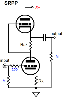
Now, we move on to the SRPP circuit, the fantastically famous SRPP circuit. This time, the sense resistor, Rak, is located in the circuit’s middle and the bottom triode receives the input signal. As the bottom triode increases in conduction, the external load resistance and resistor Rak both see an increase in current flow. The greater the flow of current, the more negative the top triode’s grid becomes relative to its cathode, which decreases the top triode’s current conduction. Once again, the delta between top and bottom triodes current conduction is delivered into the load resistance. Okay, so the sense resistor can be located at the top of the two triodes or in between the two, but could it also be placed at the bottom of the two triodes? For example, say the top triode received the input signal and the bottom triode followed along, could the bottom triode’s cathode resistor also function as the sense resistor?
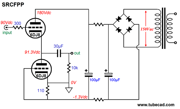
The above circuit is one possibility. This circuit uses a floating power supply that does not directly attach to the circuit’s ground; instead, the power supply (battery in the schematic) completes its circuit through the two triodes and the 110-ohm sense resistor. In other words, in a stereo setup, each channel would require its own floating high-voltage power supply. This time, imagine a 300-ohm external load. As the top triode’s grid sees a positive-going voltage pulse, the top triode increases its conduction, which flows through both the bottom triode and the external 300-ohm load—and, most importantly, through the 110-ohm resistor. Remember the power supply is floating and the ground is only the circuit voltage reference. This is the sticking point for many, as they are used to a high-voltage power supply terminating into ground and for them current can always flow into (or out of) a connection to ground. But in this circuit, current must flow from the battery’s negative terminal up through the bottom triode and then through the top triode and finally into the battery’s positive terminal. So when the top triode increases it conduction, the 110-ohm current-sense resistor sees the increased current flow and develops a greater voltage drop across its leads, which makes the bottom triode’s grid more negative relative to its cathode, which forces the triode’s conduction to lessen. Once again, the delta between top and bottom triode current conduction is delivered into the load resistance. If the top triode increased it conduction sufficiently, the bottom triode would turn off altogether. If the top triode ceased conducting entirely, the bottom triode would increase its conduction greatly. Wait a minute, how can the bottom triode conduct at all if the top triode no longer conducts current from the battery? Seems like quite a paradox doesn’t? Well, the answer is that the 30µF coupling capacitor holds a +91.3V voltage charge, which combined with the 300-ohm load resistance completes a circuit with the bottom triode. No, this setup will not power the bottom triode for hours or even minutes, but it will for long enough for low audio frequencies to be produced. Now I will flesh out the circuit further, so that we can see how a floating power supply is implemented.
Now, let have some fun and shift the ground to the bottom triode’s plate.
No way, this cannot work. The top triode will vary its conduction in response to the input signal, but that has nothing to do with the bottom triode, right? Wrong. If the top triode increases its conduction, then that increase must flow through power supply and the 110-ohm sense resistor and the bottom triode in parallel with the external load resistance. Since the 110-ohm resistor sees a larger voltage drop, the bottom triode must decrease its conduction, so the load resistance must see the difference. Note how, unlike a cathode follower, the output signal is no longer in phase with the input signal. Moreover, like an SRPP circuit, this circuit can deliver voltage gain. In fact, it is an upside-down SRPP! (See blog number 329, under the title "Inverted SRPP with Floating Power Supply.") Okay, I understand that all this soaring high above is making some dizzy due to the thin air, so let’s come down to earth with an SRCFPP circuit that does away with the floating power supply, where ground is ground, power supplies are grounded, and men are just ordinary guys.
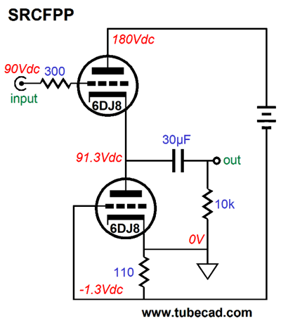
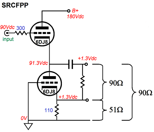
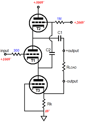
The functioning remains the same as the first SRCFPP, but the ground is at the bottom of the 110-ohm resistor.
Yes, we got ground where we want it, but now we have two outputs, a positive and a negative output. We can no longer, however, terminate the load resistance into ground; instead, the external load must attach across the bottom triode. What happens if we, being contrary creatures, do terminate the load into ground? No push-pull operation, as the sense resistor would fall outside the AC current flow into the load. Thus, making the bottom triode just an expensive resistor replacement. Is having two dissimilar outputs a big deal? Absolutely, as it means that we cannot hook up this SRCFPP circuit to a stereo power amplifier with RCA input jacks, as the negative output swings in phase to the positive output, albeit at much smaller level, which means that both channels cannot be tied together at their cathodes. On the other hand, the whole point of this circuit, like the White cathode follower and SRPP, is to produce class-A, push-pull operation of two triodes, so a low-impedance load, such as a headphone driver element can be driven. The key phrase in the last sentence was "low-impedance load," for if a high-impedance load is being driven, there's no need for push-pull operation of the two triodes, as push-pull operation offers greater current swings that are not needed with high-impedance loads.
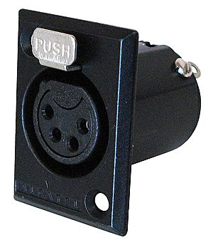
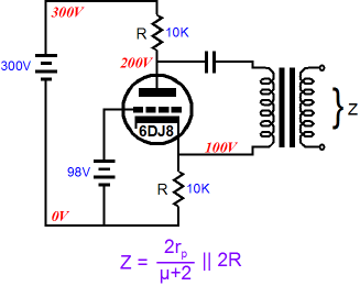
Well, if we are willing to change the termination on our headphones from the three-segment phone plug to either two mono phone plugs or a single four-connector XLR plug, then it little matters that we have two outputs, as the each headphone driver has no idea what it is hooked up to and it can safely float at 1.3Vdc, as it sees a net DC voltage differential of 0V. In other words, since the DC offset is the same for both positive and negative outputs, the DC delta is zero volts. Nor does touching 1.3Vdc present any danger to the listener (excepting, of course, American trial lawyers, whose delicate fingers could suffer millions of dollars of trauma). Note and marvel at the sneakiness of this SRCFPP, as the cathode resistor does double duty of biasing the bottom triode and acting as the sense resistor that creates the anti-phase current swings between top and bottom triodes. The next step is to figure out the formula for the optimal cathode resistor, Rk, value. Since both the White cathode follower and the SRPP share the same formula for the optimal sense resistor, Rs = (rp + 2Rload) / mu We should see if it works in the SRCFPP. Indeed, it does work, which makes sense as all three circuits function in fundamentally similar way: AC current flows through an external load resistance and a sense resistor, which creates an anti-phase signal to drive the other triode in a balanced push-pull fashion; and since both triodes share in driving the external load, the load's impedance is effectively half as burdensome, so it is effectively twice is nominal value. Thus, the triode's mu and rp and the load resistance must be included in the formula. The next question is What is the output impedance of the SRCFPP? If we pull back and look at the topology, we see that it is quite similar to the split-load phase splitter, except that the plate resistor has been replaced by a triode.
If the top triode’s grid terminated into its cathode, the top triode would present an impedance equal to its plate resistance. But as the triode’s grid is effectively grounded, the output impedance at is cathode is vastly lower, being equal to rp/(mu + 1). Thus, the formula for the output impedance of the SRCFPP is Zo = 2rp/(mu + 2) || (rp/(mu + 1) + Rk) I plugged the values for the SPICE model of the 6DJ8/69922 into the formula and got 92 ohms as the answer. I then ran some SPICE simulations on the SRCFPP and got the following results.
SRCFPP History
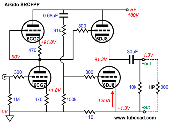
Since I couldn’t add a resistor, I wondered if I could use the bottom output triode’s cathode resistor as the sense resistor. I was taking a shower, drawing schematics on the frosted glass, as I have done for decades, when I instantly imagined the following circuit. (It's amazing how a half of my brain groks a new circuit in its entirety, while the other half lags behind, trying to catch up.) Aikido SRCFPP Audio Aikido is a family of many electronic techniques that all share the same characteristic: the power-supply noise is used against itself, rather than relying on brute force techniques, such as using huge, massive inductors and Foster-beer-sized capacitors or complex high voltage regulators to purge power-supply noise at its source—or relying on tons of negative feedback within the amplifier to reduce the power-supply noise after the fact, i.e. once the noise has already leaked into its output. Could I perform an Aikido transformation upon the SRCFPP?
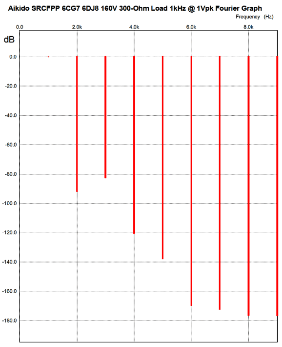
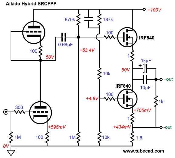
My first thought was no, absolutely not, as null of power-supply noise at the positive output would incur the addition of power-supply noise at the negative output—a giant step sideways, in other words. But the more I thought about, I realized that would be possible to create a ratio of power-supply noise at each output that equaled each other, thus nulling the noise at the load (not relative to ground). The above schematic shows an Aikido SRCFPP circuit that yields an amazingly good PSRR, low distortion, and low output impedance. I ran some SPICE simulations on the circuit and here are the results. First, the distortion breakdown.
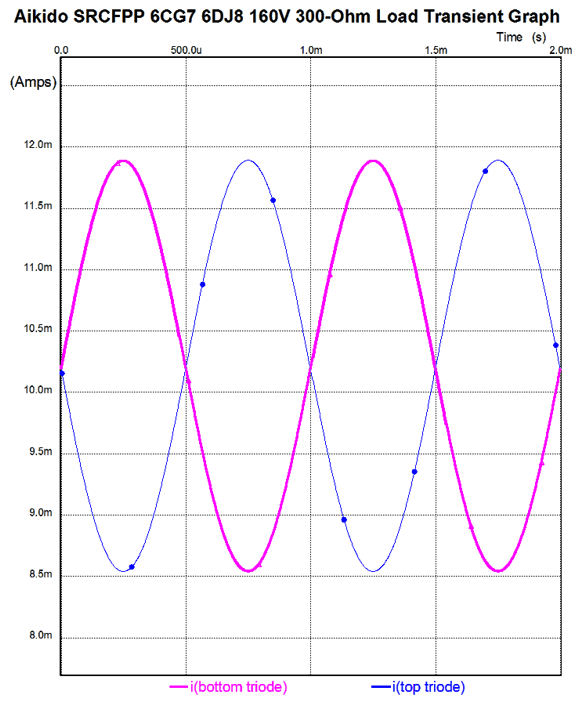
Next, we see the current balance between top and bottom output triodes.
Note the 12AX7 as the input tube. Why? We need the extra gain, as the output transformer will reduce the output voltage by its winding ratio. For example, the 3:1 winding ratio, which implies an impedance ratio of 9:1, will reduce the output voltage swing to a third, e.g. 3Vpk becomes 1Vpk. (Perhaps, the 12AX7 would provide too much gain and a 6N1P or 5965 would be a better choice for an input tube.) Also note that the transformer’s secondary is grounded, which means that we can use the standard 1/4th inch, three-segment, phone plug and jack with the output transformer.
Revealed by SPICE simulations, the PSRR figure for the above circuit is insanely good for a tube circuit that uses no global feedback loop, about -60dB. The next question is, How hard would it be to hack an existing Aikido into an Aikido SRCFPP? It could be done in about twenty minutes, if you are an experienced hacker. Not everyone is, however. The key point is to hook up a four-terminal jack for the headphones. Speaking of four-terminal, balanced output jacks, this circuit does not deliver true balanced outputs relative to ground, as the positive output is about five times bigger than the negative output, which also swings in phase with the positive output. Besides, a balanced load that was ground-centered could never be used with this circuit. Remember this circuit requires that the load current be confined to a path that flows through the sense resistor; adding a center-tapped ground connection would ruin that exclusive current path.
As far as the headphone drivers are concerned, however, the SRCFPP output is perfectly balanced, as the drivers make no direct connection to ground. Relative to ground, the negative output does offers a lower output impedance, but with a floating headphone driver, the driver element only sees a 90-ohm resistance in parallel with it and talking about different output impedances makes about as much sense as saying that a 90-ohm resistor presents two resistances, 10 ohms at one end and 80 ohms at the other end.
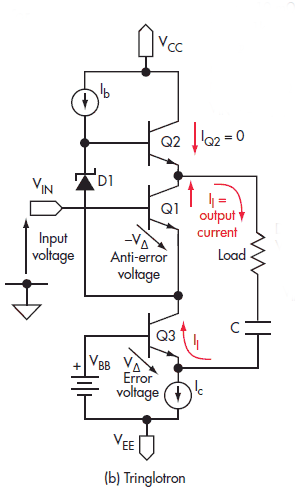
Remember the Tringlotron?
In one of my transformations of this solid-state topology into vacuum-state, I came with the following variation, which yielded lower distortion than the version that used a constant-current source in place of the cathode resistor.
As can readily be seen, this topology is similar to the SRCFPP, as both present a plus and minus output. The advantage the SRCFPP holds over this circuit is that the SRCFPP uses one fewer triodes, requires only 2/3 as much B+ voltage, and uses only one coupling capacitor. In addition, the three triodes in the tall totem-pole configuration are a pain to heat up, as topmost triode’s cathode is 200Vdc from ground, which makes keeping the heater-to-cathode voltage safety margin all but impossible to meet without using at least two separate heater power supplies. Moreover, and most importantly, the SRCFPP is true push-pull topology that can deliver up to twice the idle current into the external load, whereas this Tringlotron variation can only deliver up to the idle current, being fundamentally a single-ended amplifier. In other words, given the same idle current, the SRCFPP will swing twice as much peak voltage and four times the power into the low-impedance load as the Tringlotron can.
MOSFET SRCFPP
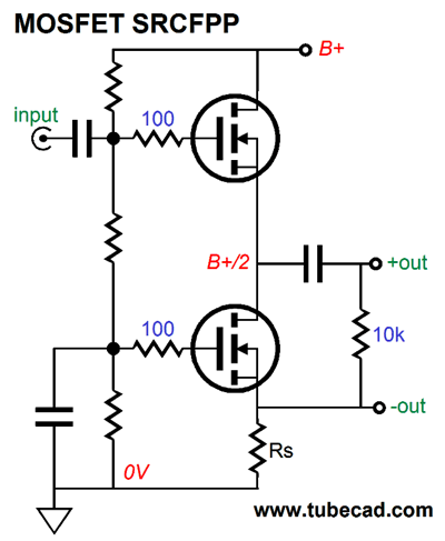
Very Zen, but not single-ended. Making an actually useable MOSFET SRCFPP will take a few more parts.
Remember that this is a power buffer, not a voltage amplifier. In other words, a big input signal will be required. But as tubes can swing large voltages relatively easily, this should not that big a deal. For example, I would build an Aikido based on a 12AX7 as the input tube and a ECC99 as the output tube, which would yield a voltage gain close to 50 (+34dB). And do not forget that the SRCFPP is a strict class-A, push-pull buffer, not a cheesy, high-end-faux, class-A design. In other words, expect a lot of heat and massive heatsinks and huge power transformer. We are dealing with hard reality here, not glossy ads in audio magazines. Okay, could we combine the Aikido frontend with a MOSFET SRCFPP output stage? Sure, here is just such a hybrid circuit.
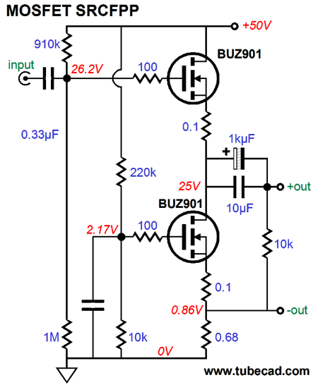
The intended load is 50-ohm headphones and the hefty 270mA of idle current through the MOSFETs ensures big output swings (up to 24Vpk). I forgot to label the tube used, which is a 6DJ8, although many other tubes could be used, such as the 6AQ8 or 6CG7 or 6072… Note the 50% AC voltage division of the B+ noise due to the two 10k resistors that that feed the bottom MOSFET. The tube input stage will also pass 50% of the power-supply noise to the top MOSFET's gate, creating a noise null at the output. Super sneaky, no?
One Last Word If you know of an earlier incarnation of this circuit, please let me know about it.
Next Time
//JRB |
I know that some readers wish to avoid Patreon, so here is a PayPal button instead. Thanks.
John Broskie
And
High-quality, double-sided, extra thick, 2-oz traces, plated-through holes, dual sets of resistor pads and pads for two coupling capacitors. Stereo and mono, octal and 9-pin printed circuit boards available.
Designed by John Broskie & Made in USA Aikido PCBs for as little as $24 http://glass-ware.stores.yahoo.net/
The Tube CAD Journal's first companion program, TCJ Filter Design lets you design a filter or crossover (passive, OpAmp or tube) without having to check out thick textbooks from the library and without having to breakout the scientific calculator. This program's goal is to provide a quick and easy display not only of the frequency response, but also of the resistor and capacitor values for a passive and active filters and crossovers. TCJ Filter Design is easy to use, but not lightweight, holding over 60 different filter topologies and up to four filter alignments: While the program’s main concern is active filters, solid-state and tube, it also does passive filters. In fact, it can be used to calculate passive crossovers for use with speakers by entering 8 ohms as the terminating resistance. Click on the image below to see the full screen capture.
Tube crossovers are a major part of this program; both buffered and un-buffered tube based filters along with mono-polar and bipolar power supply topologies are covered. Available on a CD-ROM and a downloadable version (4 Megabytes). |
|||

 The key feature is placement of the ground at the bottom triode’s cathode, which allows the power supply to move up and down relative to the ground, as the power supply is not directly tied to ground.
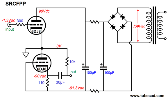

 Mr. Wilkins' amplifier is like an SRPP on steroids. The interesting thing is that I couldn’t get the amplifier I built to stop oscillating. Quite possibly, Mr. Wilkins used carbon-composition resistors, whereas I used the newest metal-film resistors, which may have made all the difference, as those old carbon resistors are non-inductive by design (of course, it might have been just bad wiring practice on my part). I moved on to other topologies and only dug out Mr. Wilkin’s circuit from of my memory recently, when I was trying to come up with a way to implement the Aikido push-pull with my old PCBs that don’t allow a sense resistor to be used at the top of the circuit.
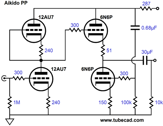
 Very good indeed. I even ran some simulations with a 32-ohm load and the results were still surprisingly good. If you need to drive 32-ohm headphones, then the better approach is to use an output transformer with a winding ratio of 3:1.
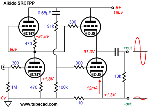


| www.tubecad.com Copyright © 1999-2012 GlassWare All Rights Reserved |