| John Broskie's Guide to Tube Circuit Analysis & Design |
09 July 2022 Post Number 560
PCBs Are Here!
Dual-Voicecoil Loudspeakers Thus, we grudgingly accept compromises. Each audiophile reveals his single most treasured sonic attribute in the loudspeaker he buys. He might choose subterranean bass response or shimmering highs, while others choose midrange purity or near-photographic imaging; still others demand rocket-liftoff volume, SPLs powerful enough to unglue their dentures. If you have enough money, you might be able to buy three or four sonic glories in one loudspeaker; sadly, few are so lucky.
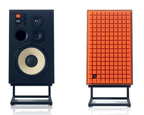
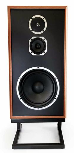
Either out of desperation or misguided nostalgia, old loudspeaker designs are being resurrected, such as the JBL L100 and the KLH Model Five.
(Get ready for the upcoming revival of the CD. Retro is the big new thing it seems.) In contrast, I like to look in the out-of-the-way corners that others ignore. For example, crossover design has been for the last 75 years pretty much settled science. All that could be invented had been invented by the year 1950 or so—well, that is what many believe. As they see it, you just look in an old textbook and follow the formulas. At the same time, if you actually look at the crossovers used in highly esteemed loudspeakers, you seldom see any crossover remotely close to the 75-year-old design in those books. As I inspected crossover design, I discovered many wrong turns and a few unexplored possibilities, which explains why I post so much on this topic. Recently, my attention has been drawn to dual-voicecoil (DVC) subwoofers and woofers. (As far as I know, no one makes a DVC midrange, a huge failing in my view.) DVC subwoofers and woofers, however, grant us far more options. For example, we can passively sum the deep bass from both channels in a mono single DVC subwoofer; all that has to be done is to devote one voicecoil to the right channel and one to the left. Or, we can choose between placing the two voicecoils in series or in parallel. With two 4-ohm voicecoils we can create either a 2-ohm or an 8-ohm load. Each has its uses. In addition, DVC woofers offer the possibility of undoing the low-frequency diffraction loss as the loudspeaker moves its sound radiation hemispherical at frequencies above 400Hz to omnidirectional at frequencies below 400Hz; this change creates a -6dB loss at low frequencies.
The workarounds are to place the speaker enclosure on the floor or near a corner or apply a bass-boost to the signal entering the power amplifier. The DVC workaround is to engage one of the woofer's voicecoils only at frequency below 400Hz (or so), while its brother voicecoil runs fullrange, i.e. from resonance to the first crossover frequency.
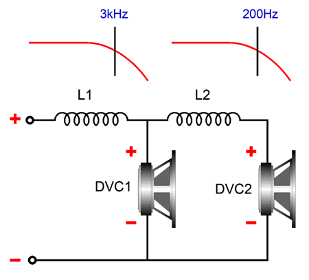
The problem with this workaround is that the nominally 8-ohm loudspeaker drops to 4 ohms at low frequencies. On the other hand, if the loudspeaker cabinet held an internal power amplifier, we could drive one woofer voicecoil from it, which would unburden the external power amplifier and allow us to tweak the transition frequency and the amount of boosting applied to match our listening room and preferences. Well, my recent meditations and inspirations have been at the other end of the frequencies, i.e. at the crossover frequency. Let's assume a two-driver loudspeaker with a 7-inch DVC woofer and a tweeter. Normally, if we wish to preserve a flat phase response, we must use a 1st-order crossover, either a parallel or series arrangement.
These crossovers yield a flat frequency, phase, and impedance response. Sadly, they are close to impossible to pull off in reality, as the poor, wee, delicate tweeter cannot tolerate the gentle 1st-order slope of 6-dB per octave and -20dB per decade. (The only workaround I can imagine is to use two fullrange drivers with crazy low crossover frequency, say 600Hz, between them, as a 1st-order crossover would work well then. Indeed, the resulting sound might prove breathtaking.) The usual industry workaround is to give the tweeter a higher-order crossover filter, with the woofer either matching the slope or using a lower-order filter. This works reasonably well, but it fails to deliver the promise of phase-flat output. Well, here is where a DVC woofer would come to the rescue. All we have to do is to imagine that the DVC woofer was two woofers, not one.
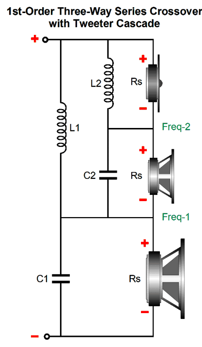
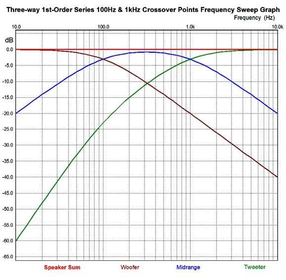
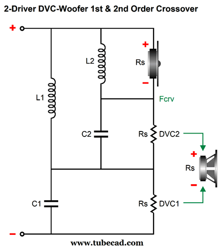
We start with a 1st-order, 3-way crossover with cascading tweeter filtration. We can use either the parallel or the series arrangement.
In this series crossover with tweeter cascade, the tweeter sees two high-pass filters, not one, as the crossover between the woofer and midrange also applies to the tweeter. Thus, the tweeter starts with a 1st-order slope but ends with a 2nd-order slope. This arrangement certainly helps, but it does not protect the tweeter as much as a 2nd-order crossover would have. True enough, as the 2nd-order slope for the tweeter only kicks in at the first crossover frequency, 100Hz in the example below.
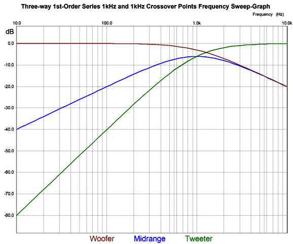
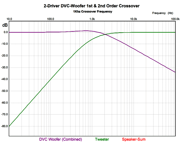
But what if the crossover frequency between the woofer and midrange in this design was at the same frequency as the crossover frequency between the midrange and tweeter? The tweeter would now see a 2nd-order filter and the woofer would run up to the single 1kHz crossover frequency, while the midrange would see a narrow band-pass filter centered at the 1kHz crossover frequency.
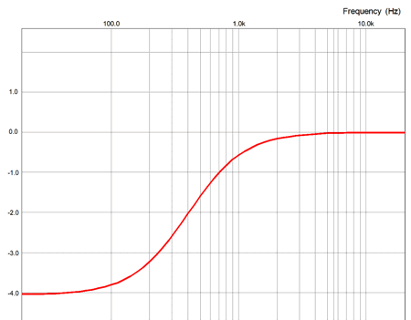
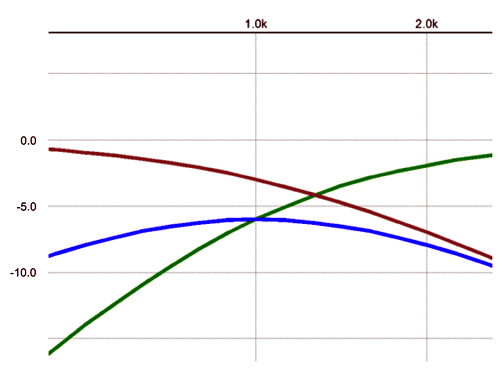
Compare the tweeter plot at 10Hz in this graph to the previous graph. The same crossover frequency, but the tweeter is down an additional -20dB at 10Hz, which is all for the good. If we zoom in at the crossover frequency, we see that both the tweeter and midrange are down -6dB at 1kHz, while the woofer is down only -3dB.
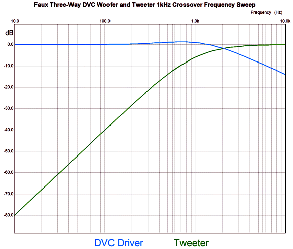
The entire crossover is still fundamentally a 1st-order type and the loudspeaker response is still flat in frequency, phase, and impedance. The next step is to imagine the woofer and midrange sharing the same diaphragm, which is precisely what a DVC driver does. With DVC woofer, we must combine the woofer and midrange plots.
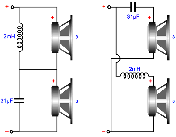
What could the crossover look like? I can see only three possibilities. Let's start with the series.
The series crossover topology works best with voltage-output amplifier, which 99.99999% of power amplifiers are. Why does it work best? See post 481 for the details. The one problem with the series topology is that it does not allow for bi-wiring. Is that a deal breaker? You decide, but after many sonic shootouts I definitely prefer bi-wires to single wires. In contrast, the parallel crossover topology works best with current-output amplifiers, which dang few are. (Tube-based power amplifiers often straddle the two opposites, as their relatively high output impedance, as high as 4 ohms for some single-ended amplifier without negative feedback loops, prevents them from being seen as true voltage amplifiers, but even 4 ohms is not enough to count as the infinity that true current-output amplifier requires.)
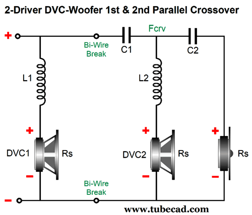
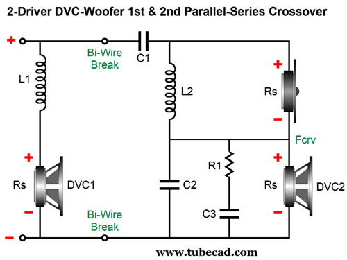
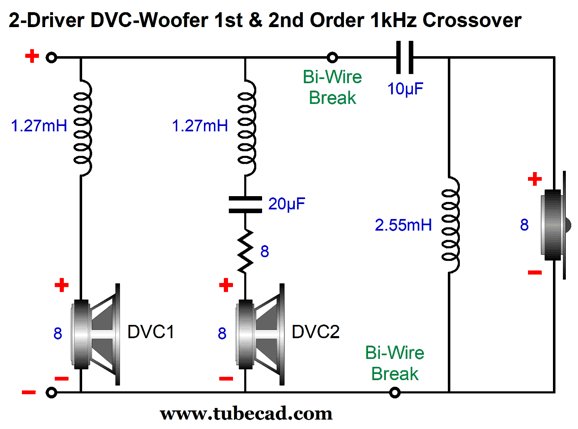
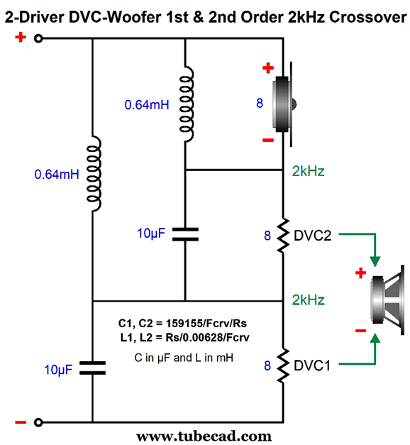
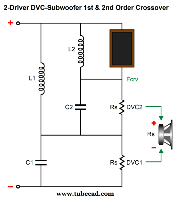
As we can see, the parallel crossover topology allows for easy bi-wiring. (Do not forget that the DVC woofer is effectively two drivers as far as the power amplifier and the speaker cable is concerned.) An added feature to this arrangement is that the crossover inductors are in series with the DVC voicecoils, which means that we can subtract the voicecoil's own inductance (Le) from the required inductor value. For example, if 0.64mH is needed, but the voicecoil presents 0.14mH, then we would use an inductor with 0.5mH of inductance. In other words, the DVC woofer's own otherwise parasitic inductance becomes a feature and part of the crossover design. Nonetheless, I would use the following arrangement instead, a parallel-series arrangement.
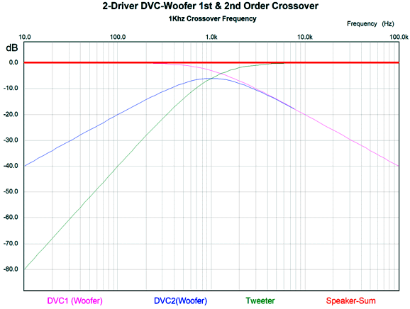
The tweeter and one DCV voicecoil are in series, so the DCV2 voicecoil needs a Zobel network, whereas the other voicecoil doesn't, as its inductance becomes part of the crossover. Bi-wiring is still an option. Still, all three arrangements produce the same great results. Here are the SPICE-generated frequency plots.
Note that the tweeter is down -6dB at the crossover of 1kHz, not the usual -3dB. In addition, note that the two DCV voicecoils converge above about 3kHz, with one extending down to DC, while the other peaks at the crossover frequency and then falls away with 1st-order slope. At 10Hz, this second voicecoil will see 1/100th the signal that the other voicecoil sees; the tweeter, only 1/10,000th as much. I won't bother showing the phase or impedance plots, as they are ruler flat. What we need to do is to combine both DVC voicecoil signals into one. In SPICE, we do not add the two dB plots together.
Instead, we must combine the AC voltage signals that they receive first, and then apply the dB conversion.
Here is the result.
Note that the DVC woofer cone produces a 1dB bump at the crossover frequency, but the loudspeaker sum is still flat. How's that possible? We need to include the relative phases of the two drivers. The math needed for the parts values for all these crossover topologies is embarrassingly simple:
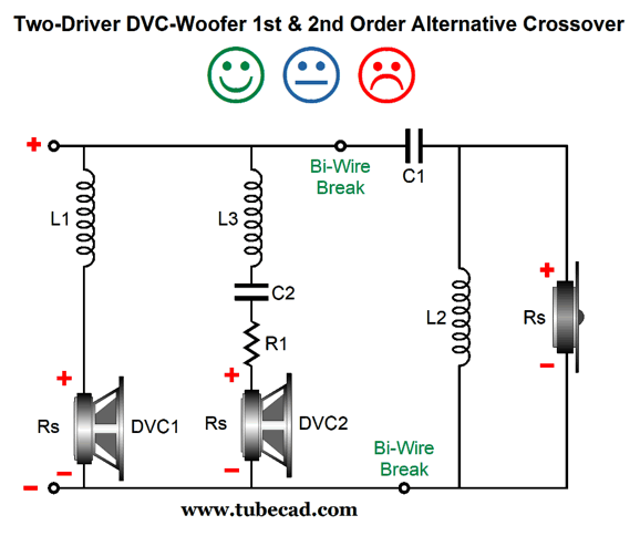
Where C in µF and L in mH. To see how a Zobel network is calculated, see post 539. Some might argue that the bi-wire split goes too low, as one of the DVC woofer's voicecoils is getting it signal along with the tweeter. I see the point, but do point out that the signal sent to that DVC voicecoil is band-pass filtered and is down -40dB at 10Hz. Nonetheless, I love electronic challenges. So is it possible to make the bi-wire break at the tweeter? Yes, we can. It took some heavy thinking, but I came up with it.
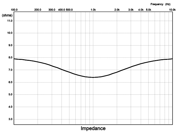
We now have three inductors and one extra resistor, but we obtain the same flat frequency and phase plots with voltage-output power amplifiers, but not with current-out amplifier, as the impedance plot is not flat.
Sadly it dips. Had it peaked instead, we could have added an impedance-flatening network. In addition, the part values require a bit more skill in determining.
The tweeter requires a 2nd-order filter with a Linkwitz-Riley Q of 0.5, which results in the tweeter being down by 6dB at the crossover frequency. Well, it's bad enough that we need that we need three inductors, not two, but even worse that one must be twice the inductance. Let's compare this to the series version.
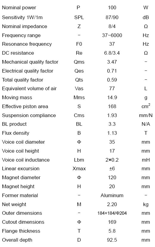
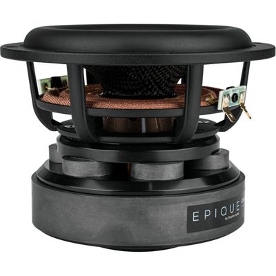
Note that the crossover frequency is now 2kHz, not 1kHz. To get to the 1kHz values, just double all the shown capacitor and inductor values. The huge problem we face is that so few DVC woofers are made today. Focal used to make a fine DVC 7-inch woofer, but no longer. The only readily available DVC woofer I could find was the Aurum Cantus AC-180F1D 7-inch DVC carbon fiber and polypropylene woofer, which Parts Express sells for $95.98. Its specs look decent:
The frequency bandwidth out to 6kHz looks promising. I would like to know how the SPL was measured, as the two figures might be for a single driven voicecoil and then both in parallel; or, it might have been with both in parallel (4-ohm load) and then with both in series (16-ohm load).
DCV Subwoofers
At the other extreme, we can buy a 18-inch DVC subwoofer, with two 2-ohm voicecoils. Many dual 8-ohm voltage subwoofers are available, as well. We can applied the same technique as shown previously, but with a vastly lower crossover frequency, say between 80Hz to 200Hz. In addition, we could add the subwoofer to an existing fullrange loudspeaker. Well, if it were truly a fullrange speaker, we probably wouldn't need a subwoofer, so let's say a typical two-way speaker with a 5 to 8 inch woofer and a tweeter, what used to called—long ago—a bookshelf speaker. Of course, if you are young, you might have to ask an old-timer what a bookshelf is and, possibly, what a book is.
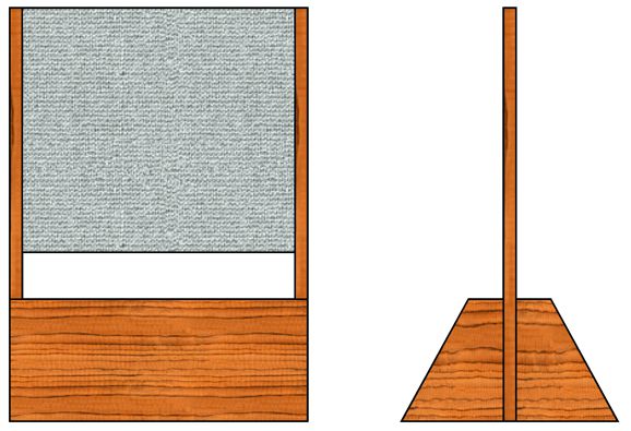
The crossover imposes a 2nd-order slope on the existing loudspeaker that will greatly unload the fullrange speaker. Ideally, both the subwoofer and the fullrange loudspeaker should share the same resonating frequency in their enclosures; in addition, the two should share the same bass loading, sealed-box or ported, to keep the phases in line near the crossover frequency. Ideally, the existing fullrange loudspeaker would present a flat impedance. Good luck with that. With the exception of some transmission-line loaded woofers and some planar loudspeakers (electromagnetic types, not electrostatic), most loudspeakers exhibit an impedance plot that resembles the outline of my nearby Rocky Mountains. This brings us to the Magnepan loudspeakers, as several of their models, such as the Magnepan 0.7, offer a truly flat impedance. This 4-ohm dipole loudspeaker is on my short wish-list. I have owned Magnepan speakers before and it's hard to forget their ear-pleasing sound. So, how would I implement the subwoofer and crossover? To start, I must bring up a conversation I had at an RMAF with Siegfried Linkwitz.
We had been talking about crossovers, and I questioned his approach of placing a midrange above a top-firing woofer, fearing that the bass waves would disturb the midrange cone. He explained that his approach actually prevented such a disturbance, as the midrange was used open-baffle, so it was essentially a dipole. He went on to explain that if the woofer were mounted on the same board with the midrange, then we would have to worry, as the bass waves would be present only on the front of the midrange, not its back (assuming a sealed box for the woofer). In other words, the midrange was effectively blind to the woofer's output. After giving it a few seconds thought, I realized that he must have been right. (Imagine a sail perpendicular to the wind.) Well, the Magnepan 0.7 is a dipole loudspeaker, so we can mount it above a top-firing subwoofer.
The problem any planar loudspeaker faces is rocking back and forth. Long ago, I borrowed a dangerously powerful lab laser from a friend and tacked a small square of bright aluminum foil to the Maggie's grill cloth near the top of the speaker. I then shot the laser beam onto the square and saw the beam hit my vaulted ceiling. As the music played, the red dot made a bouncing oscilloscope trace across my ceiling. My workaround was to attach thick steel L-sections to the back and create a tripod by extending a steel tail behind the speaker, which dug into the carpet. The red dot's travel decreased by an easy tenfold, but the speaker's weight went up by the same amount. The improvement in sound was staggering, very Quad-like to my ears. Well, with the chunky subwoofer cabinet below the planar loudspeaker, we can extend up solid wood or metal rails to lock the dipole in place far more tightly than the existing thin stands can. Let's bring are attention back to a great loudspeaker, the Quad 57, which was two-way electrostatic design with the tweeter section sandwiched between two woofer sections, thus predating the D'Appolito arrangement by decades. If I remember correctly, the crossover frequency was 500Hz.
I always thought that Magnepan should release their own version with magnets and the same horizontal arrangement of woofer panel-tweeter panel-woofer panel. Of course, they would run into the same problem that Quad did in that it's hard to get loud deep bass from a small dipole. Well, with the a top-firing subwoofer and a 120Hz crossover frequency, the planar drivers would have a lot less to deal with.
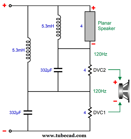
Here is what the crossover looks like for a 120Hz crossover frequency.
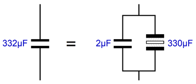
By the way, the series arrangement of the crossover is not just my prejudice, as that is what Magnepan uses in some of their new loudspeakers. The 332µF capacitors are actually two capacitors in parallel: one film, the other non-polarized electrolytic.
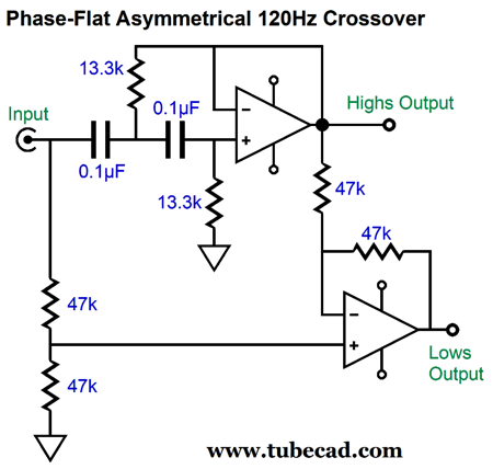
Note the subwoofer holds two 4-ohm voicecoils. Also, note that the planar speaker enjoys 2nd-order filtration of frequencies below 120Hz, which should prove enough to prevent annoying rattling. (Planar dipole loudspeakers, both electromagnetic and electrostatic, often employ poorly damped diaphragms to improve the low-bass response. To get decent low-frequency extension would require a hugely wide dipole, as in six to eight feet or so.) If we wanted to implement the crossover actively, we could use the following circuit, whose two outputs mimic the passive crossover exactly.
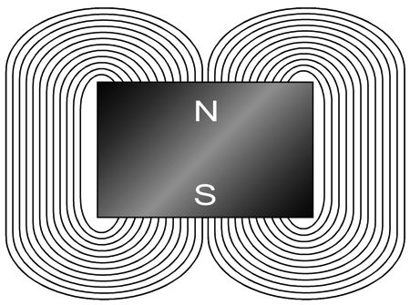
We can even translate the high-pass 2nd-order filter with tubes. The huge advantage the active crossover and the sub amplifier bring is the ability to adjust the amount of bass augmentation with the turn of a potentiometer. With the passive setup, we might end up having to attenuate the subwoofer driver, as the Maggies are woefully inefficient. Speaking of inefficient, here is where my mind takes me. The Magnepan loudspeaker use long strips of magnets and a plastic diaphragm with long lengths of wire or metal foil glued to them. (I watch a video of their small LSR speaker being built and the amount of manual labor was staggering.) As the current flows through the conductors, the current flow interacts with the magnet field, causing the diaphragm to move back and forth.
In order to keep the load resistance within reason (4-ohms), the wire used in the old Maggies seemed to be some type of bronze alloy, not copper or silver. Why not use high-temp Kapton flexible PCB material with honest-to-God copper traces, which would end up weighing less due to its lower resistance?
We could, but we end up with another Apogee planar loudspeaker with a DCR of 1 ohm. Okay, this is where most say, Wrong turn," but I say just the opposite: it's a feature, not a bug.
Here is my idea: we forgo the 4-ohm target and purposely create a diaphragm voicecoil with a DRC of 0.5 ohms. We then couple the 0.5 ohms zigzagging trace to a special step-down transformer's secondary. The transformer must offer a winding ratio of 4:1, as the resulting impedance ratio will be 16:1, as 4² equals 16; thus, the 0.5 will reflect as an 8-ohm load on the primary.
Most importantly, the copper traces will experience four times the current flow that the primary undergoes. This is vitally important, as it is only current flow within a magnetic field that prompts the speaker movement. Increase the current flow by fourfold and we gain 12dB in SPL, which would bring the Magnepan's SPL-per-watt up to a thunderous 96dB. (Actually, with the change to an 8-ohm load, we would incur a 3dB loss, so 93dB would prove more likely, which is still a staggering improvement.) Think single-ended power amplifiers. Wait, what about the transformers, wouldn't they be a pain to design and build? Not really, as the ideal load for a transformer is zero ohms, not 5k or 10k. Well, 0.5 ohms is close. Do the math and you see that very little inductance is needed; in other words, far fewer windings. Since the tweeter portion crossovers at about 500Hz, the required inductance for its transformer is truly tiny (0.16mH), which might make an air-core transformer possible. (Imagine an air-core toroid wound on a wax former, which we would melt away once the winding was done.) In fact, we could use an autoformer with a tap at 25% of the winding length. The unseen big problem is that the transformer's primary will present a near dead short to the power amplifier's DC offset. This is not a big deal with a tube power amplifier with either an output transformer or an OTL with a large output coupling capacitor. But it is a big deal to a direct-coupled solid-state power amplifier. Do the math: given a DC offset of only 50mV and a DCR of only 0.001 ohms, what will the output stage power dissipation be? The workaround used with transformer-couple ribbon tweeters is always to use a coupling capacitor on the primary, even in a bi-amped system, where the tweeter gets its own power amplifier. Well, with the DVC subwoofer and the passive crossover in place, the transformer would also be capacitor coupled.
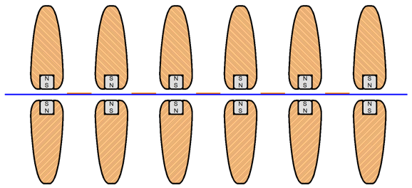
By the way, it's possible that with the greatly improved SPL, the subwoofer might not be able to put out enough output to match the transformer-coupled planar loudspeaker. One workaround would be to use two 4-ohm DVC subwoofer drivers (in series). In addition, since the subwoofer is on the floor, it should realize a +6dB boost, as it radiates hemispherically. Let's return to the Maggie design. Much like an electrostatic loudspeaker, the Maggies use perforated metal sheets on at least one side if not both sides of the diaphragm. The perforated sheet is needed to hold the magnet strips in place. On the web, there's much controversy over which sounds better, magnets atop the perforated metal sheet or below next to the diaphragm. Ideally, no perforated sheet would be used, as it just gets in the way. I often wondered why the Maggies held rubberized magnetic strip tape instead of truly powerful solid-metal magnets. My guess is that stronger magnets would refuse to stay opposite to each other with like poles, south to south or north to north, which would overwhelm the flimsy perforated aluminum sheet. A small tragedy this is. If the current flow is limited, we could then compensate with a stronger magnetic field. Okay, it's time to think like Alfred.
Einstein used a powerful mental trick: you start with your biggest problem, the problem you are not likely to eliminate ever, and make this problem the first principle of your new system. For example, he faced the problem that the speed of light was, contrary to common sense, fixed. You travel at half the speed of light and turn on your flashlight and the light leaves at the same speed as it did when you were stationary. He accepted the fixed speed as the first principle of his new system of physics. A good move. Okay, to make a go of an electrodynamic planar loudspeaker, we will need conductors, a diaphragm, and a magnetic field. Note that I didn't write "magnets," as we could use an electromagnet instead. We hope to place as little in front of the diaphragm as possible and to prevent the magnets from flying apart due to the like poles being placed head to head. Let's now take the first problem, the perforated metal sheet, and make being an obstruction into a feature. How? We borrow my idea from post 400: an acoustic-lens/stator for an electrostatic speaker. Here is a longish quote from the post:
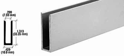
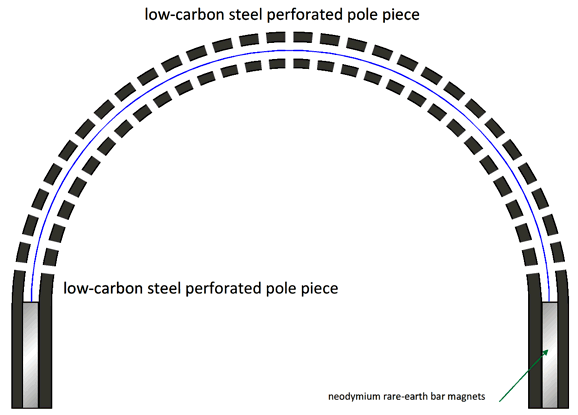
Affix a bar magnet to the top of the long rectangular strips of wood or aluminum and we have a sonic lens and a sturdy support for the oppositional magnets. I would round the other end of the strip. We could have custom wood molding trim stock or aluminum extrusion produced, so the long rectangular neodymium rare-earth magnets could be held firmly in place.
The long bar magnets would fit in the notch.
They do sell satin anodized 1/4th inch aluminum extrusions that are 1.25" deep, so the center would need to be filled with 1 by 0.25 inch wood strips, which the long square-profile neodymium rare-earth bar magnets would rest upon.
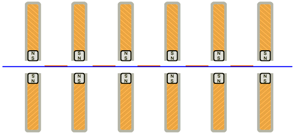
Since neodymium rare-earth bar magnets are easily ten times more powerful than rubberized magnetic tape, we could space the strips further apart. Routered top and bottom pieces of wood would accept and seat the extrusions in place.
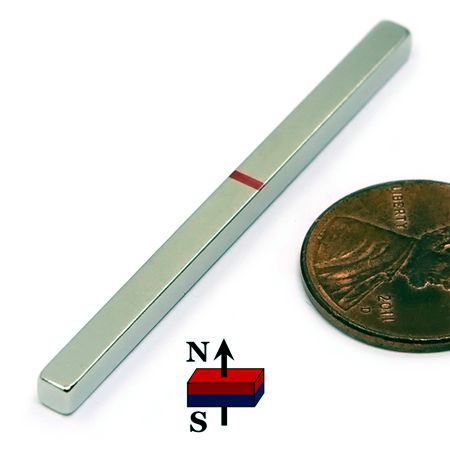
No more flimsy sheet of perforated aluminum. No more planar loudspeaker rocking forwards and backwards with the music, as the structure is quite rigid and immovable. Most importantly, we can move away from rubberized magnetic tape, which is barely strong enough to hold up a few paper clips, and move on to neodymium rare-earth bar magnets, which can hold up a hammer. I went searching for super-strong magnetic tape and I saw a specification of 675 gauss; in contrast, a 2 by 0.25 by 0.25 inch neodymium rare-earth bar magnet offers 13,500 gauss and a lifting weight of 18.6 lbs. The website, magnets4sale.com, also sell a 2 by 0.125 by 0.125 inch neodymium rare-earth bar magnets for $0.83 each and they can lift 8 lbs. (I don't know what the bulk price would be.) Bear mind that we can probably get away with 1-inch gaps between the bars in a long column.
True, this last remade Maggie loudspeaker would no longer be as thin as the original, being about four inches thick. About 30 or 40 years ago, I met Jim Winey, the founder of Magnepan, at an audio show. We had a good talk and he was quite receptive to new ideas. I wish I could talk to him today. Stereophile magazine held a fine interview with Winey back in 2003, which is well worth reading.
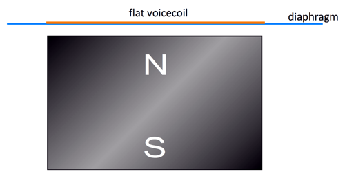
Flexible Electrodynamic Planar Loudspeaker (FEPL)
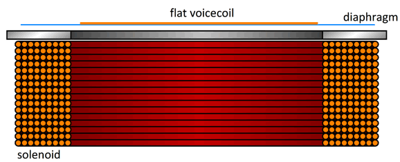
To see how this works, imagine the coil all on its own. Next, imagine an AC current flow through the flat voicecoil and picture the alternating magnetic field created by the current flow. When this field attracts to the magnet, the diaphragm moves closer to the magnet; when in opposition, away from the magnet.
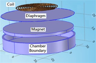
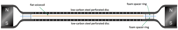
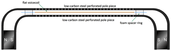
Truly an interesting design. My first thought was that it's a pity the bottom of the magnet is wasted, so I thought of adding voice-coiled diaphragm to the bottom side, making either bipole or dipole sound radiator. But then I was just warming up. What if we took two low-carbon steel perforated discs that we press into a dish shape and then added a ceramic ring magnet and voice-coiled diaphragm in between?
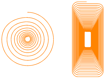
The magnetic field much prefers the steel discs to air, so it will travel inside the steel beginning from there the magnet touches the steel, distributing the magnetic flux across the voicecoil, completing and tightening the magnetic circuit. The voicecoil can appear on both sides of the diaphragm, with through-hole vias (tiny conductive paths that establish electrical connections between different PCB layers) bridging the two coils at their centers, spiraling in opposite directions. The voicecoils need not be circular, as a long rectangular spiral could be used.
With a long rectangular spiraling voicecoil we can make a tall rectangular dipole, much like the Maggies. Since we would have moved away from a circular driver, we could change the shape of the magnetic pole pieces of perforated low-carbon steel.
This is the top view. Now, imagine the width is 12 inches and the length extending to four feet. Since we can alter the shape of the magnetic pole pieces of perforated steel, we could incorporate an exponential or tractrix horn shape. Just try to imagine a dipole horn. Or, we could copy the curved electrostatic loudspeaker and round the magnetic pole pieces.
The way this works is that the diaphragm is only stretched and affixed at its top and bottom. Double-sided adhesive foam tape is used both to anchor the diaphragm and to provide the needed spacing. The neodymium rare-earth bar magnets would need to be glued to one magnetic pole piece, as the magnets themselves would hold the other magnetic pole piece in place. (This arrangement might allow repair or replacement of the diaphragm, as glue solvent and a lot of force would allow the magnetic pole pieces to be separated. I had better stop here, as I could go on forever. But I will leave you with one last idea. We return to the original FEPL speaker design, but replace the big fat bar magnet with an air-core solenoid (inductor).
Music Recommendation: The Soul Of Ben Webster
If you think you dislike jazz, you probably dislike Bebop, Hard Bob, Jazz Funk and Fusion, and Acid Jazz. All the tracks (all 26 of them) on this album, The Soul Of Ben Webster, are melodic and drip with soul and fluidity. His signature breathy playing is what your soul hungers for, so give it a prolonged listen.
//JRB
Did you enjoy my post? Do you want to see me make it to post 1,000? If so, think about supporting me at Patreon.
User Guides for GlassWare Software
For those of you who still have old computers running Windows XP (32-bit) or any other Windows 32-bit OS, I have setup the download availability of my old old standards: Tube CAD, SE Amp CAD, and Audio Gadgets. The downloads are at the GlassWare-Yahoo store and the price is only $9.95 for each program. http://glass-ware.stores.yahoo.net/adsoffromgla.html So many have asked that I had to do it. WARNING: THESE THREE PROGRAMS WILL NOT RUN UNDER VISTA 64-Bit or WINDOWS 7, 8, and 10 if the OS is not 32-bit or if it is a 64-bit OS. I do plan on remaking all of these programs into 64-bit versions, but it will be a huge ordeal, as programming requires vast chunks of noise-free time, something very rare with children running about. Ideally, I would love to come out with versions that run on iPads and Android-OS tablets.
|
I know that some readers wish to avoid Patreon, so here is a PayPal button instead. Thanks. John Broskie
John Gives
Special Thanks to the Special 77 To all my patrons, all 77 of them, thank you all again. I want to especially thank
All of your support makes a big difference. I would love to arrive at the point where creating my posts was my top priority of the day, not something that I have to steal time from other obligations to do. The more support I get, the higher up these posts move up in deserving attention.
If you have been reading my posts, you know that my lifetime goal is reaching post number one thousand. I have 440 more to go. My second goal was to gather 1,000 patrons. Well, that no longer seems possible to me, so I will shoot for a mighty 100 instead. Thus, I have just 23 patrons to go. Help me get there. Thanks.
Support the Tube CAD Journal & get an extremely powerful push-pull tube-amplifier simulator for TCJ Push-Pull Calculator
TCJ PPC Version 2 Improvements Rebuilt simulation engine *User definable
Download or CD ROM For more information, please visit our Web site : To purchase, please visit our Yahoo Store: |
|||


| www.tubecad.com Copyright © 1999-2022 GlassWare All Rights Reserved |