| John Broskie's Guide to Tube Circuit Analysis & Design |
29 October 2019 Post Number 481
Boo!
All Stepped Attenuators on Sale
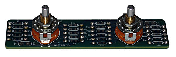
The 6-position rotary switch offers -1dB decrements, while the 11-position switch delivers -6dB decrements, resulting in 66 volume steps from 0db to -65dB.
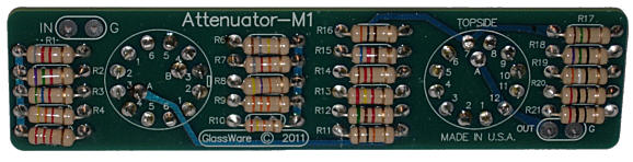
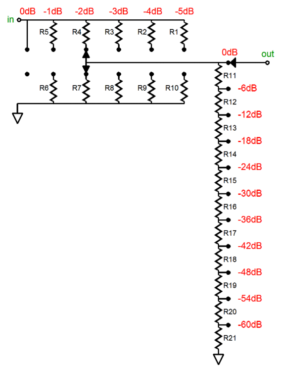
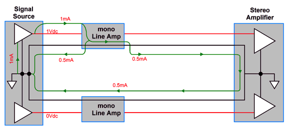
The M1 combines a series and a shunt attenuator, so never more than 12 resistors are in the signal path. I love the coarse (-6dB steps) and the fine control 9-1dB steps), as the coarse knob gets me close, while the fine allows obtaining the exact volume level and doubles as a balance control, as one M1 is used per channel. (It is amazing how many recordings greatly benefit from a 1dB balance adjustment.) And if your goal is to build two mono-bloc line stage amplifiers, each on its own chassis and with its own power supply, the M1 is the way to go. Speaking of dual-mono line stages, they work beautifully with dual-mono power amplifiers, but not with stereo power amplifiers, as the power amplifier's two channels share a common ground connection, which undoes the dual feature of the two once-independant line stages.
To fully see what is going on in the schematic shown above, check out post 434. Be sure to check out the attenuators at my Glass-Ware Yahoo store.
Crossover Epiphany
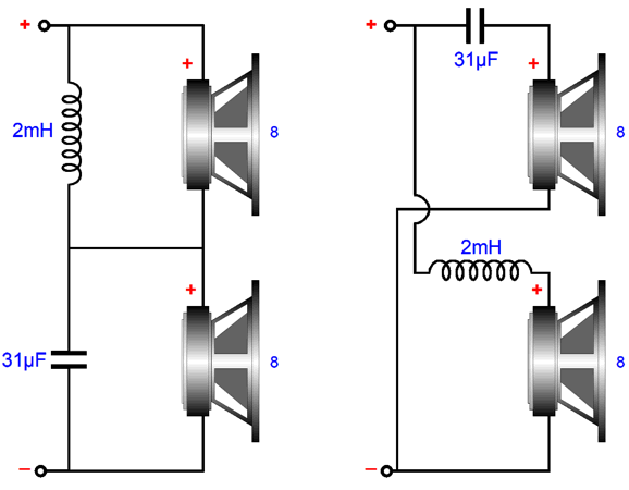
Well, a few weeks ago, I had an epiphany, a loudspeaker crossover epiphany, which I was glad to have experienced, but which nonetheless made me feel foolish for not having undergone earlier; but first some history. About 30 years ago, I got a phone call out of nowhere from a retired Ph.D. in electrical engineering, who had spent his working life devoted to electronic filter design. He had heard of my (unearned) reputation as a crossover wizard* and he wanted to get together to talk crossovers. During our conversation, I learned that he had always been concerned with loudspeaker crossovers and now that he was doing freelance design consultations for speaker companies, mostly pro-audio types, he was being paid to develop better crossovers. He had tried scores of designs and alignments, but after years, if not decades, of experimentation, nothing had beaten the first-order, series crossover. It alone delivered the sonic goods. The problem was, of course, that all 1st-order crossovers made huge demands on the loudspeaker drivers to provide wide bandwidth and they offered little protection to delicate tweeters, particularly those in pro-audio applications.
I asked him why the series arrangement bested the far more common parallel arrangement. Here was his answer, which I detailed in post 402.
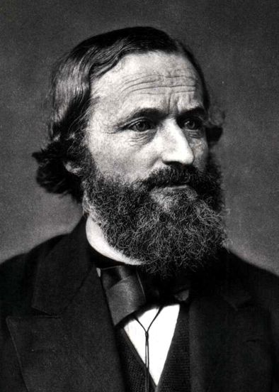
Seemed reasonable. Well a few weeks ago, as I looked over the simple series crossover topology and some of my more elaborate variations on it, I had my epiphany. Or, put differently, Gustav Kirchhoff’s Current Law (KCL) had kicked me in the head.
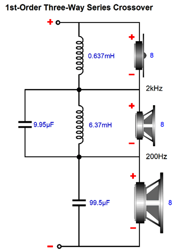
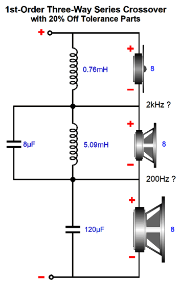
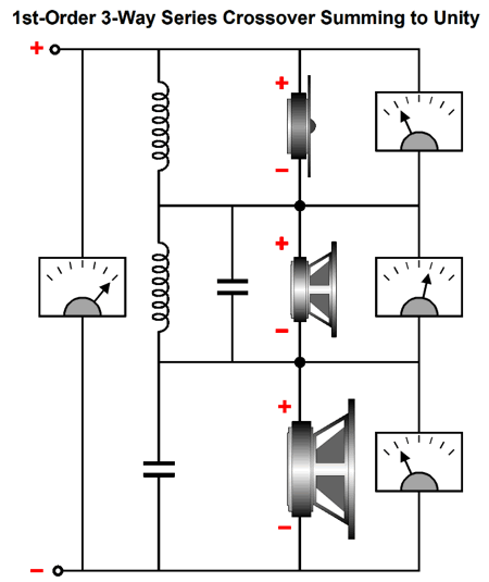
Kirchhoff's famous and fundamental law(s), which is the starting point for any circuit analysis, states that since charge is conserved, “The algebraic sum of all currents entering and exiting a node must equal zero.” Similarly, his Voltage Law states, "The directed sum of the potential differences (voltages) around any closed loop is zero." What this has to do with the first-order, series crossover topology is that the sum of the voltage drops across the drivers must equal unity with what the amplifier is putting out. In other words, of course the first-order, series crossover topology would work best; it has to, as the sum of voltages across the drivers must total to the amount of voltage that the power amplifier is delivering. Here is an example three-way series crossover. The crossover frequencies are 200Hz and 2kHz, which nicely divide the 20Hz to 20kHz audio bandwidth up into three equal slices, as 200Hz/20Hz equals 2kHz/200Hz which equals 20kHz/2kHz.
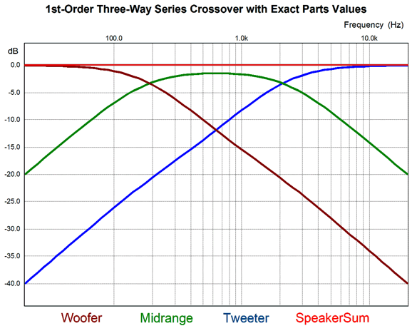
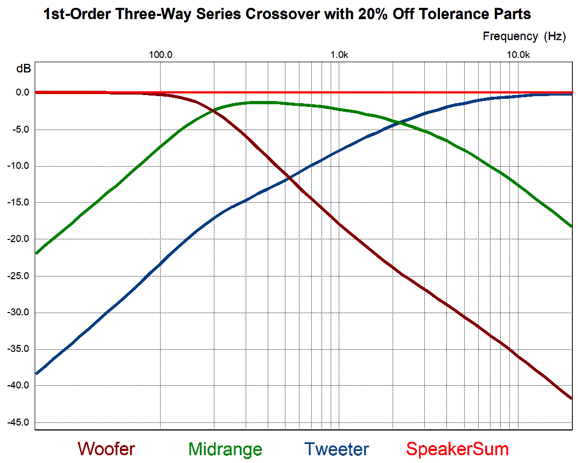
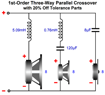
Assuming perfect loudspeaker drivers, the sum of the three drivers' acoustic outputs will equal unity, i.e. a sonic analog of the amplifier's output signal. NO MATTER WHAT. For example, let's use the wrong crossover part values, which can easily and unintentionally happen, as crossover capacitors often come in 20% tolerances. Note that the inductor and capacitor values are all off by 20%. Now, let's look at the SPICE simulation of the three drivers' outputs and their sum. Unity. A straight line. A flat frequency response. But all three drivers see the wrong part values and each driver delivers a wobbly cut-off slope; nonetheless, we got a flat summing plot. In fact, we could double the error in values and still get a flat frequency and phase response. In contrast, if we use these same values in the first-order parallel crossover topology, we get different results.
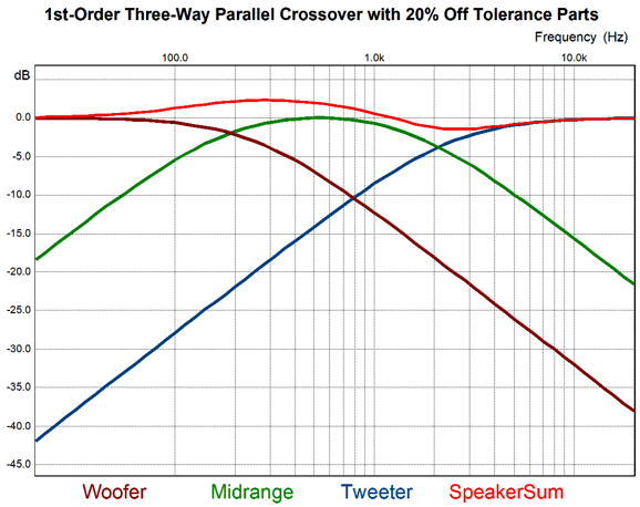
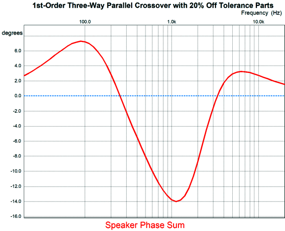
Here are the resulting plots.
Not so good, not flat, although the drivers' cuttoff slopes look better. Moreover, the phase is no longer flat, whereas the series arrangement with the off part values did deliver a flat phase line. In other words, the first-order, SERIES crossover topology, either the two-way or three-way or four-way or five-way versions, always yields unity; it has to, as the sum of the drivers' voltages must sum to unity. Of course, the drivers can and probably will let us down, but at least we have the potential of achieving unity. By the way, this amazing result only holds true when the loudspeaker is attached to a voltage-out amplifier, an amplifier that puts out a fixed voltage, but with a varying current. With a current-output amplifier, an amplifier that puts out a fixed current flow, but whose output voltage varies, the parallel crossover would win and the series crossover would lose.
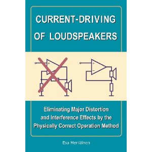
In Esa Meriläinen's excellent book, Current-Driving of Loudspeakers: Eliminating Major Distortion and interference Effects by the Physically Correct Operation Method, he mentions that the series arrangement works best with voltage-out amplifiers and the parallel works best with current-out amplifiers. When I read his book, I just took his word for it; now, I understand why this must be so. And I must mention that both the series and parallel arrangements only deliver a flat impedance plot when the correct crossover part values are used.
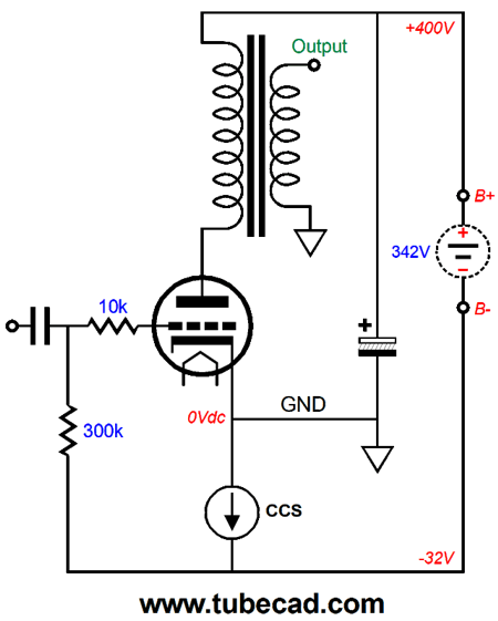
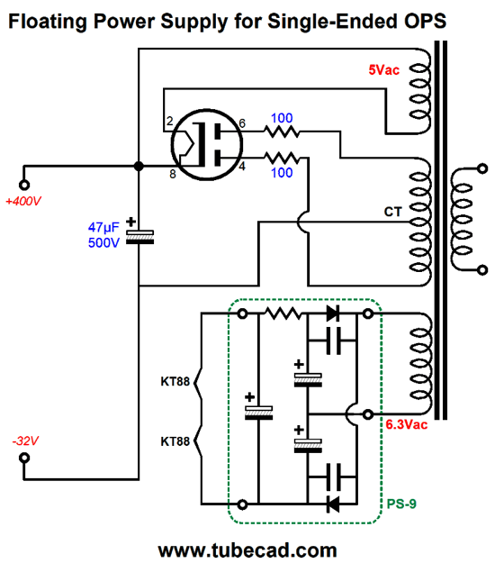
Single-Ended Output Stage with CCS Mojo The power transformer's secondary center-tap is not grounded! Ground now falls at the output tube's cathode and the floating monopolar power supply creates a bipolar power supply because of our placing ground there. This means that stereo will require two separate power transformers.
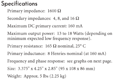
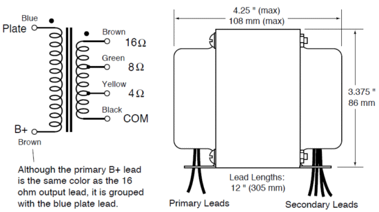
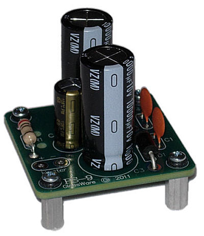
I have return to this topology because I have been thinking about using two KT88 output tubes in parallel with one UBT-1 output transformer, whose specs are shown above. If I gave each its own cathode-located constant-current source, auto biasing would be easy, but I would lose the PSRR enhancement, as the two would not shield the circuit from the power-supply noise. The workaround is to use only matched output tubes. The problem with matched tubes is that we seldom know the degree to which they are matched. For example, many tube sellers simply array three boxes, with one labeled "low," another "medium," and the last is labeled "high." Then the output tubes are measured and placed into one of the three boxes. Now, this might be a reasonable thing to do, if the tubes come from the factory already tightly matched. Usually, they don't. I have sorted a hundred pentodes before and the variations were extreme. On the other hand, I know that Antique Electronics Supply and New Sensor put a lot more effort into their tube matching. One danger we face, however, with using two output tubes and the Down-Upside-Down arrangement is that since only one constant-current source is used, one output tube will be over biased when its partner is missing from its socket. The workaround is to place the two output tubes heater elements in series. This way if one tube is missing, the other never completes its heater circuit. We must use a 12V or 12.6V heater power supply, which will freak many die-hard tube enthusiasts. I know, as I get email from them all the time. If the tube is a 6.3V type, then you must use a 6.3V heather power supply, they repeatidily tell me. In point of fact, I always run my regulated heater power supplies with a 12Vdc output voltage, as it lessens the rectifier losses and increases the regulator voltage headroom and often lowers the regulator heat dissipation—all are desirable attributes. Moreover, the slightly lower heater voltage extends the tube's life, thus, 12Vdc, not 12.6Vdc. Here is an example of a high-voltage floating power supply with a voltage-doubler heater power supply. Note that ground makes no connection anywhere in the power supply. Also note that one of my PS-9 PCB is used to convert the 6.3Vac heater voltage into 12Vdc.
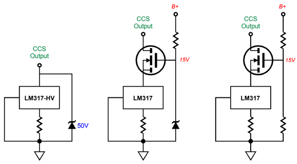
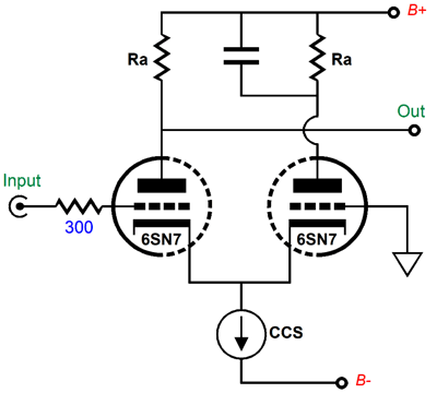
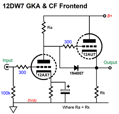
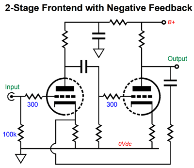
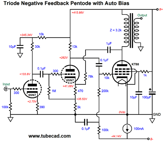
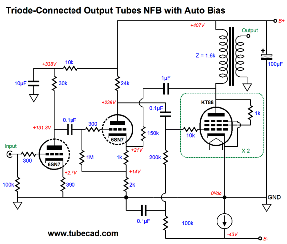
Where is the constant-current source? We could use a single LM317-HV, shunted by a 50V Zener that protects the three-pin regulator. Or, we could use a plain LM317 in cascode with a high-voltage MOSFET, which could use either a Zener or a two-resistor voltage divider to establish the MOSFET's gate voltage. Why not use a depletion-mode MOSFET instead as the constant-current source? We could, but they are not a current stable with changes in temperature as the LM317 is. So far, we have an output stage and floating power supply and constant-current source, but no input and driver stages. We could use a cathode-coupled gain stage, with its own constant-current source long-tail loading. Another possibility would be a 12DW7-based frontend. The 12DW7 holds dissimilar triodes, a 12AU7 and 12AX7 type. We use the 12AX7 triode as the input stage, as it develops the most gain; then we use the 12AU7 triode in a cathode follower configuration. Another possible setup would be to use two grounded-cathode amplifiers in cascade, with a short negative feedback loop. Unlike a global negative feedback loop that would extend from input cathode to the output transformer's secondary, this short loop is not likely to provoke headaches. One last possibility is to make a negative feedback loop between the second grounded-cathode amplifier and the bottom of the output transformer's primary. The idea here was that we could wire up the output pentode as a pentode and use the second grounded-cathode amplifier to control and correct the pentode's output. In SPICE simulations, the results were not as good as those obtained from triode-connected pentodes, alas. So, here is the triode-connected version.
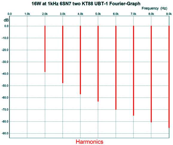
Note how the constant-current source must source enough current for both the output stage and the input stages. In other words, if the input tube is missing, the output tubes will have to draw the missing current flow. The constant-current source needs to draw about 170mA, due to two KT88s, each drawing 75mA. Here is the SPICE-generated Fourier results for full output (16W).
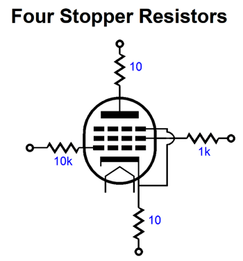
THD is a tad over 1%. At 1W of output, the THD falls to almost 0.1%. By the way, I always use stopper resistors, although I don't always show them in my schematics.
They must be soldered at the socket pins to be effective in curtailing oscillations; in addition, the resistors should be non-inductive types.
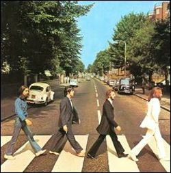
Music Recommendation: The Beatles' White Album
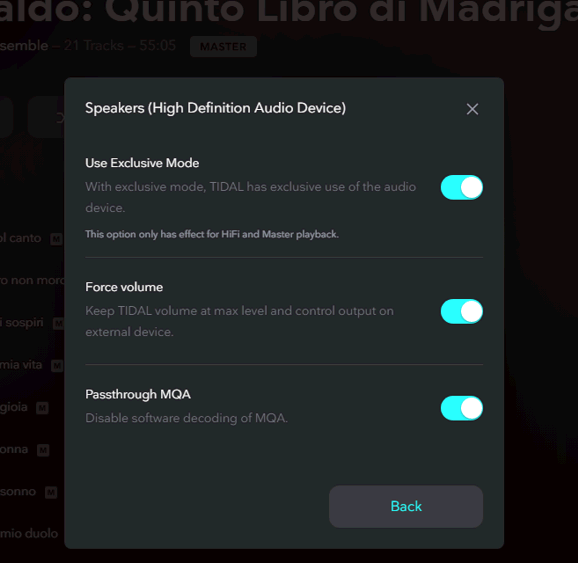
By the way, when listening to Tidal, be sure to get the settings right. For example, be sure to let your DAC take control of the stream and do the MQA unfolding itself, if it can.
//JRB
*Putative Crossover Wizard
User Guides for GlassWare Software
For those of you who still have old computers running Windows XP (32-bit) or any other Windows 32-bit OS, I have setup the download availability of my old old standards: Tube CAD, SE Amp CAD, and Audio Gadgets. The downloads are at the GlassWare-Yahoo store and the price is only $9.95 for each program. http://glass-ware.stores.yahoo.net/adsoffromgla.html So many have asked that I had to do it. WARNING: THESE THREE PROGRAMS WILL NOT RUN UNDER VISTA 64-Bit or WINDOWS 7 & 8 or any other 64-bit OS. I do plan on remaking all of these programs into 64-bit versions, but it will be a huge ordeal, as programming requires vast chunks of noise-free time, something very rare with children running about. Ideally, I would love to come out with versions that run on iPads and Android-OS tablets.
|
John Gives
Special Thanks to the Special 86
I am truly stunned and appreciative of their support. In addition I want to thank the following patrons:
All of your support makes a big difference. I would love to arrive at the point where creating my posts was my top priority of the day, not something that I have to steal time from other obligations to do. The more support I get, the higher up these posts move up in deserving attention.
If you have been reading my posts, you know that my lifetime goal is reaching post number one thousand. I have 519 more to go. My second goal is to gather 1,000 patrons. I have 914 patrons to go. Help me get there.
Support the Tube CAD Journal & get an extremely powerful push-pull tube-amplifier simulator for TCJ Push-Pull Calculator
TCJ PPC Version 2 Improvements Rebuilt simulation engine *User definable
Download or CD ROM For more information, please visit our Web site : To purchase, please visit our Yahoo Store: |
|||


| www.tubecad.com Copyright © 1999-2019 GlassWare All Rights Reserved |