| John Broskie's Guide to Tube Circuit Analysis & Design |
02 July 2022 Post Number 559
Happy July 2nd!
♦ ♪ ♦ ♪ ♦ ♪ ♦ ♪ ♦ ♪ ♦ ♪ ♦ ♪ ♦ More Diamonds
When transistor Q1 sees a positive-going input signal at its base, its emitter follows the signal, which decreases the current flow through the transistor. At the same time, transistor Q2 sees the same positive-going input signal at its base, except that its emitter voltage is shifted up by about 0.6V. Since its emitter resistor sees a greater voltage drop, the transistor must be experiencing a greater current flow. Conversely, when transistor Q1 sees a negative-going input signal, it increases its current flow, while transistor Q2's flow decreases. This is anti-phase current conduction in a nutshell. Well, when two cascading active devices undergo anti-phase current swings, their nonlinearities tend to cancel. In contrast, when their current swings are in series, the nonlinearities tend to add together. (Sadly, nature does not allow us to make a P-version of a triode. Believe me, they tried.) Now it's time to go deeper. If you are measuring THD or just 2nd harmonic distortion, the distortion meter will show a substantial reduction in distortion. On the other hand, if you run a spectrograph of the distortion, you will see that while even-order harmonics are greatly reduced, the odd-order harmonics remain unaltered. I created three circuits in SPICE to reveal the difference.
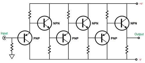
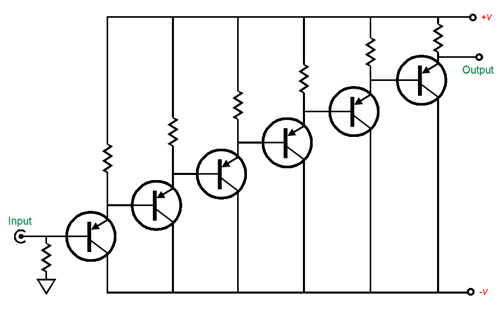
Here we see three diamonds in cascade: three pairs of MJE340 and MJE350 transistors in cascade. Next we see eight MJE350 PNP-transistor emitter followers in cascade.
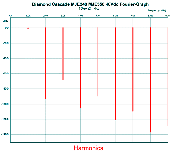
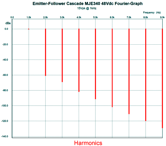
I also tried six MJE340 NPN-transistor emitter followers in cascade. I ran a SPICE simulation with an input signal of 15Vpk and got the following graph for the three-diamond cascade.
Both the NPN- and PNP-transistor emitter followers in cascade yielded the exact same plotlines:
Note the higher even-order harmonics, but the same levels of odd-order harmonics.
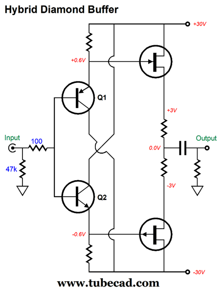
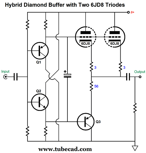
Hybrid Diamond Circuits
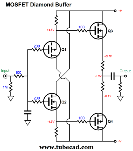
The first thing that stands out is the huge gate-to-source voltages, over 4V. Yet, the output is roughly at ground potential (0V). The second thing to catch our attention is the 1M input resistor to ground. MOSFETs do not draw DC current at their gates the way transistor bases do, so we can use a high-valued input gate resistor here, which will greatly unload the signal source. Okay, what if we mixed technologies? What if we use transistors and tubes? Yes, we do not have a P-version of a triode, but we do have P-channel FETs and depletion-mode MOSFETs.
Sadly, P-channel FETs are strictly low-voltage devices that top out at about -30V for their Vds and depletion-mode MOSFETs do exist, but they are huge power devices that also exhibit odd turn-off characteristics.
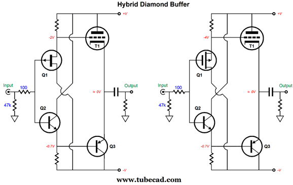
Sine a triode is a N-device, we could use a triode in the input (first stage).
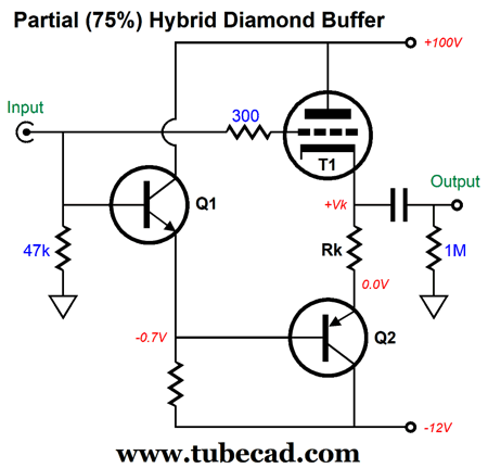
On the other hand, we could make partial diamond (75%) that forwent the PNP transistor to drive the triode's grid.
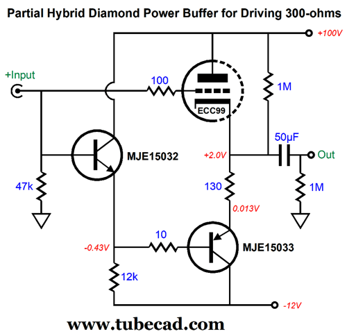
What is so interesting about this circuit is that transistor Q2's emitter is at, roughly, ground potential, so the triode will need a cathode resistor to bias it correctly with the same value that grounded-cathode amplifier would need. In addition, since the output is taken at the cathode, the cathode resistor resistance will help balanced the triode's relatively high output impedance at its cathode, which will better ensure balanced push-pull operation. Yes, the output is push-pull, with the triode pulling the output voltage up, while the transistor will pull it down. Push-pull operation means that we can get twice the symmetrical output current swings that a cathode follower could, so we get four times the potential output power compared to the equivalent cathode follower. Moreover, we can use dissimilar bipolar power-supply rail voltages. Note that the -12Vdc power-supply rail could be used to power the triode's heater element.
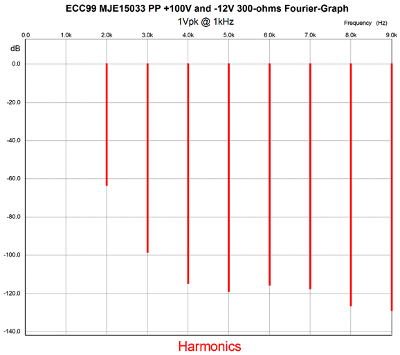
In this design example, we see an ECC99-based partial hybrid optimized to drive 300-ohm headphones. In SPICE simulations, this circuit worked beautifully, as the triode-transistor pairing with the 130-ohm cathode resistor produced equal current swings into the 300-ohm load impedance and the THD came in at about 0.1% with 1Vpk of output.
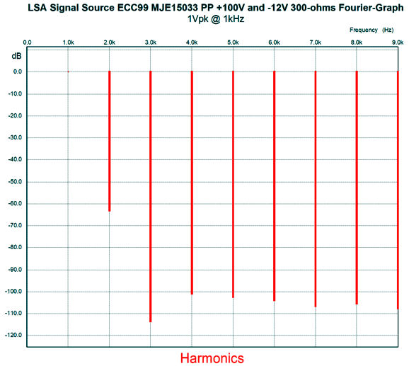
Note the strong 2nd harmonic and attenuated higher harmonics. Many DACs put out a relatively hot output signal, as much as 5Vpk, which is more than enough to drive 300-ohm headphones. In other words, this circuit would be a nice add-on for DACs that do not include a headphone output. I wonder how well a tube-based line-stage amplifier would work with this circuit, so I ran a SPICE simulation with the following changes to the circuit : 200-ohm signal source impedance and a 1µF input coupling capacitor. That's it. The actual signal source was the SPICE sinewave, but it had to travel through the resistor and capacitor.
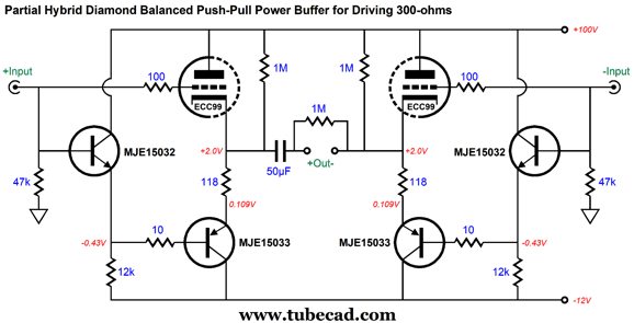
The THD is pretty much unaltered, but the 3rd harmonic is much further suppressed. Wow! The 3rd harmonic sounds like a dead hand strangling the music, as it compresses the sine-wave peaks. The less of it the better. The -15dB further reduction 3rd harmonics looks so tasty, but note that all the higher harmonics have climbed by +15dB. So, are we actually ahead or behind? We could use this circuit to drive balanced the 300-ohm headphones by doubling up on the circuit. Many DACs offer balanced output whose differential output sums to twice the unbalanced output. In addition, few run balanced power line-stage or power amplifiers, so the balanced outputs languish unused. Well, we can put them to use with the following circuit.
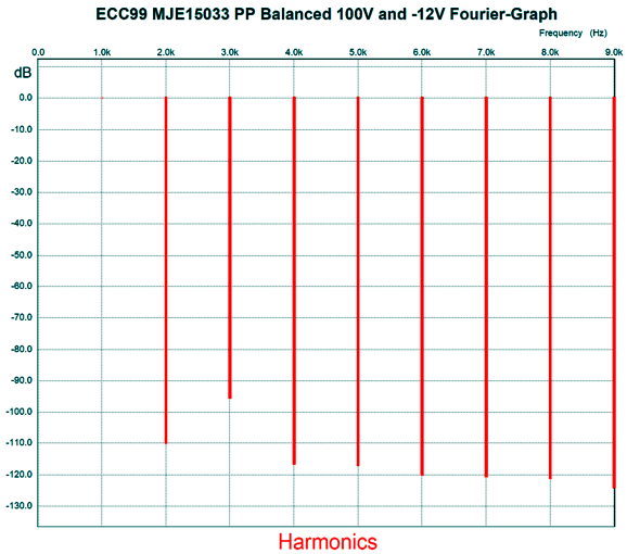
Note the change in the cathode resistor(s) value and the single output coupling capacitor. Why the change in resistor value? Each ECC99 triode effectively sees a 150-ohm load impedance, not 300 ohms. The added 1M resistors that attach to the B+ are there to give the MJE15033 PNP transistors something to bite on when the ECC99 tube is missing from its socket or still too cold to conduct. Now, we can exploit the unused balanced outputs. How well does this circuit perform? Here is the SPICE-generated Fourier graph for 1Vpk of output at 1kHz.
Yes, the 3rd harmonic is the biggest offender, but the THD is still a bit below 0.01%. Okay, what if we use a beefier triode, say the 6AS7, which is used in OTL power amplifiers to drive loudspeaker, not headphones? One problem we run into is the 6AS7's amazingly low amplification factor (mu) of only 2. Its low mu implies a big negative bias voltage. Here is my workaround.
Here we see a full diamond, albeit a hybrid diamond circuit. A monopolar power supply is used, so the B+ voltage was bumped up to 120Vdc. Note the -20V voltage differential between grid and cathode. The larger the voltage drop across the zener, the more negative the bias voltage. In contrast, a 6DJ8 triode offers a much higher mu (33 versus the 6AS7's mu of 2), so we can forgo the zener.
The 56-ohm emitter resistor equals the combined output impedance of the two 6DJ8 triodes, which ensures equal current swings and less distortion. The target B+ voltage for this circuit is only 56Vdc, with the 6DJ8 triode seeing 50V of it, while transistor Q3 sees only 6V. This power buffer can easily drive 300-ohm loads.
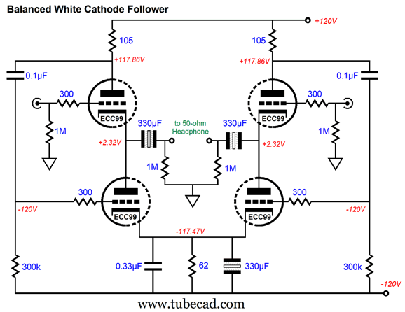
Improved White Cathode Followers
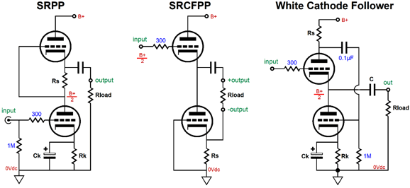
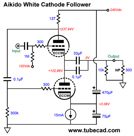
On the other hand, a White cathode follower does require two triodes, not one; in addition, it must be optimized for its intended load impedance. The White cathode follower belongs to the group of lazy push-pull tube circuits (SRPP, SRCFPP, and WCF) that accept an unbalanced input signal and internally create the needed opposite-phase signal, rather than using a balanced pair of input signals. In other words, with these three push-pull circuits we do not need a separate phase splitter circuit. This savings comes at a cost, however, as the White cathode follower must be run in strict class-A operation. In contrast, push-pull output stages that accept a balanced input signal can be run in class-AB or, even, class-B or class-C. Another downside to the White cathode follower is its relatively poor PSRR, usually only around -9dB or so. Back in post 462, I showed how to make an Aikido White cathode follower that used two large-valued capacitors to vastly improve the White cathode follower's PSRR.
This setup works, but suffers from the usual problem that electrolytic capacitors exhibit: poor capacitance tolerances. Electrolytic capacitors often hold more capacitance than labeled. Why? The thinking is along the lines of the baker's dozen in that the assumption is that the customer wants at least the amount of capacitance specified, but would be happier with more capacitance. In most power-supply applications, this assumption holds. It doesn't hold when a precise amount of capacitance is required. The workaround I have come up with is to use tight-tolerance resistors, not capacitors. This is the "cynosure resistor" technique that I have shown many times before; for example, in the Aikido cascode, split-load phase splitter, two-triode cascade... Well, I wondered if I could apply the cynosure technique to the White cathode follower. I could.
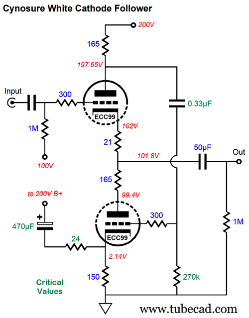
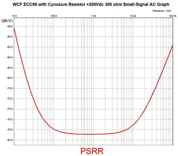
The bottom 150-ohm cathode resistor sets the idle current flow through the bottom and top triodes. The top 165-ohm current-sense resistor establishes the needed anti-phase signal for the bottom triode's grid. The current-sense resistor's value depends on the triodes used and the load impedance. One size does not fit all. In this example, the intended load is 300-ohm headphones, such as those made by Sennheiser. If a different load impedance is to be driven, then a different current-sense resistor value must be determined. In order to establish a better-balanced operation, the bottom triode also sees a 165-ohm plate resistor. The cynosure resistor value is 24 ohms. This value injects enough of the B+ voltage ripple to create a power-supply noise null at the White cathode follower's output. The 470µF capacitor blocks the B+ DC voltage but passes the AC noise. This capacitor value, along with all the other green-labeled parts values, is critical. Think RIAA equalization networks here, as we cannot just throw in whatever part values we have in our parts bin. In other words, a 330µF or 620µF capacitor will not work. The cynosure resistor is effectively in parallel with the 150-ohm cathode resistor, making a combined value of 21 ohms, which explains why a 21-ohm cathode resistor is used with the top triode. In push-pull operation, balance is all-important. By the way, this White cathode follower effectively sees a cathode resistor value of 21 ohms for both the bottom and top triodes, which results a lower output impedance. In SPICE simulations, the PSRR improved by over a thousand-fold, as it went from -9dB to -79dB!
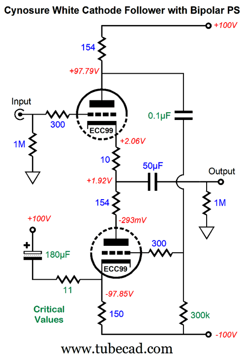
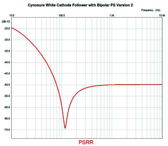
The cynosure resistor has brought us into the realm of solid-state PSRR figures. Remember, -79dB PSRR only applies to the modified White cathode follower circuit, but does not include whatever power-supply noise reduction techniques you have in play, such as chokes, RC filters, or high-voltage regulators. I wonder how well the cynosure resistor would work with the White cathode follower and a bipolar power supply. It can work, but the part values had to be adjusted, as the negative power-supply rail ripple had to be included in the operation.
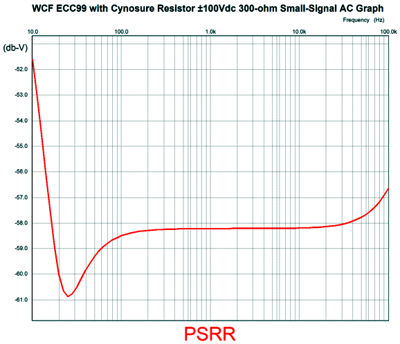
In the previous design example, we saw a B+ voltage of 200Vdc; here we see ±100Vdc. The top 154-ohm current-sense resistor establishes balanced push-pull operation with the same intended load impedance of 300-ohm headphones. This time the cynosure resistor needed to be 11 ohms and its terminating capacitor had to be 180µF. The coupling capacitor that bridges the current-sense resistor to the bottom triode's grid is now only 0.1µF. Here is the SPICE-generated PSRR graph.
Although not as good as it was with the monopolar power supply, being worse by 20dB, the deep dip at 25Hz is interesting. Still, the PSRR is vastly improved over a stock White cathode follower without the cynosure resistor. By the way, the assumption behind this circuit is that the bipolar power supply presents equal but anti-phase power-supply noise on both power-supply rails. This may not be the case in reality. Why not? Many power transformers fail to put the center-tap at exactly 50% of the high-voltage secondary. In addition, the DCR (direct-current resistance) on each side of the center-tap may not match. The simple test is to use two tightly-matched resistors (0.1%) and measure the signal at the nexus.
If we do see some signal, we have a mis-tapped center-tap problem. The workaround is to place either a choke or a resistor in series with the ground and the center-tap.
The added resistor helps undo the mis-tap. By the way, some flat-pack and some R-core power transformers absolutely offer an ideal center-tap, as they use two identical secondary winding side by side, not one atop another.
In contrast, when a center-tap is taken from a single winding, the outer winding will necessarily present a higher DCR due to its longer length of wire. In sum, the cynosure resistor can work well with the White cathode follower. Sadly, I could not derive a simple formula for its optimal value; instead, I had to use an iterative process in SPICE simulations to find all the optimal values.
While on the topic of White cathode followers, I should mention that we can use two White cathode follower circuits and a balanced input signal to drive headphone drivers with a balanced output signal. Two important considerations must be dealt with, however, if we are going to get the best results. The first is that each White cathode follower effectively sees the external load impedance halved. Thus, the 300-ohm HD800 Sennheiser headphone driver appears as a 150-ohm load. Second, the output coupling capacitor must offer twice the capacitance that it would have in a non-balanced setup. In this setup, the PSRR is stellar due to the balanced output. In other words, as long as both White cathode follower circuits leak the same amount of power-supply noise, the headphone driver never "sees" it; hence, the magic of balanced audio. Still, there is the danger of the power-supply noise intermodulating with the input signal. Additionally, I can imagine someone driving a signal transformer's primary, a center-tapped primary whose center tap is grounded, and the poor PSRR relative to ground could cause problems for the transformer. In short, improved PSRR is always a worthwhile goal. We can simplify life by using a bipolar power supply, as we will no longer need the two input coupling capacitors. In addition, we can use non-polar electrolytic output coupling capacitors (or just one output coupling capacitor).
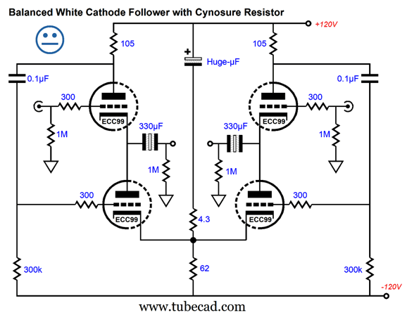
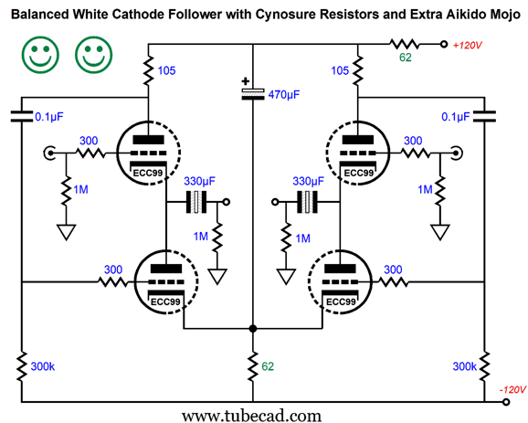
Note the shared cathode resistor, which behaves as if it were bypassed by a large-valued capacitor due to the class-A operation. So why did I bypass the resistor? Habit. The 330µF output coupling capacitors allow bandwidth down to 10Hz. Of course, we can bypass the output capacitors with a high-quality film or PIO capacitors. Okay, how do we use a cynosure resistor with this circuit? Here is what I came up with:
The 4.3-ohm cynosure resistor injects most of the positive power-supply-rail noise into the cathodes to create a noise null at the output. Sadly, we must use an insanely huge capacitor to terminate the resistor. Not good. Well, it could be good with a switching power supply whose switching frequency was above 20kHz, as a relatively small valued capacitor could be used then. I then stopped to take a bird's-eye view of the circuit.
From high above, I could readily see that the top and bottom triodes bisect the two rail voltages, which would tend to create a power-supply-noise null at the outputs in the absence of 0.1µF internal coupling capacitors relaying most of the positive power-supply-rail noise into the bottom triode grids. Then, from high above, I saw it, it being the solution. The cynosure resistor was in the wrong place.
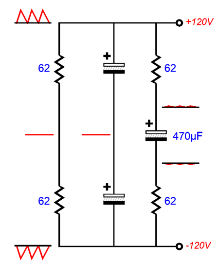
The cynosure resistor has moved to be in series with the triodes. Thus, the 62-ohm cathode resistor and the 62-ohm cynosure resistor create a two-resistor voltage divider in terms of AC signal, with a resulting noise null between the resistors.
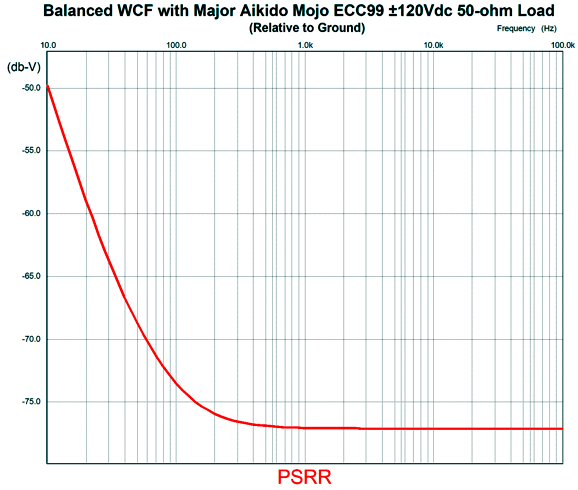
Nesting the entire audio circuit within this window of silence is a far better approach than trying to clean up a mess after it has happened. Additionally, the tubes used may not hold tightly matched triodes, which will undo the SPICE results, as all triodes in SPICE are perfectly matched. Obviously, for this trick to work, the cathode and cynosure resistor must be equal in value; in other words, using 59- or 68-ohm resistors is out. (The ambitious solder-slinger can experiment with using two chokes, each with a DCR of 62 ohms, or even a common-mode choke that holds two separate windings, but shares a common core.) This arrangement only works with a bipolar power supply; with a monopolar power supply, the two equal-valued resistors will only halve the ripple, not create a noise null. At 120Hz, the 470µF capacitor's impedance is 2.8 ohms, so the power-supply noise is greatly attenuated across its leads. How attenuated? Here is what a SPICE simulation revealed:
My quick guess was that -30dB to -40dB would be the probable PSRR figure. Wow, was I wrong, but in a good way. Having such an insight can make me happy for a few days.
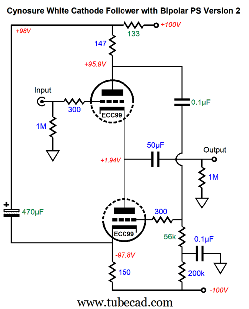
My humble hope is that someone at the MacArthur Genius Grant* committee reads this post. (I can dream, can't I? The only thing that prevents me from posting weekly is everything else in my life.) Okay, can this same technique be applied to the non-balanced version with a bipolar power supply? Here is the best-case example I could come up with for use with 300-ohm loads:
Unlike the balanced version, I found that the cynosure resistor needed to be lower in value than the cathode resistor. With the critical part values in place, this is what SPICE revealed.
Just about perfect for those whose wall voltage frequency is 60Hz, as the ripple frequency will be 120Hz, just where the deep null obtains.
Music Recommendation: Diana Panton's To Brazil With Love
Definitely, give her a listen. (Ms. Krall can use the rest.) //JRB
*From the MacArthur Foundation website:
What an odd choice of words in that last sentence, "precipice of great discovery." Precipice, really? Excerpted from American Heritage Dictionary:
Surely, a better word choice would have been "threshold." Well, my second humble hope is that the special someone at the MacArthur-Genius-Grant committee is not in the habit of reading footnotes or postscripts. With that hope in mind, here is how I would rewrite their blurb:
Not perfect, but better. Surely people select and decide and focus, whereas "selection decisions" are only the result of focused attention, not active agents. In addition, if one is going to speak or write in a regal voice, even if it's only regal boilerplate, then a sentence construction, both balanced and parallel, is essential. For example,
are not balanced, as "manifest promise" is missing its indefinite article; moreover, "of" and "for" fail to match.
Did you enjoy my post? Do you want to see me make it to post 1,000? If so, think about supporting me at Patreon.
User Guides for GlassWare Software
For those of you who still have old computers running Windows XP (32-bit) or any other Windows 32-bit OS, I have setup the download availability of my old old standards: Tube CAD, SE Amp CAD, and Audio Gadgets. The downloads are at the GlassWare-Yahoo store and the price is only $9.95 for each program. http://glass-ware.stores.yahoo.net/adsoffromgla.html So many have asked that I had to do it. WARNING: THESE THREE PROGRAMS WILL NOT RUN UNDER VISTA 64-Bit or WINDOWS 7, 8, and 10 if the OS is not 32-bit or if it is a 64-bit OS. I do plan on remaking all of these programs into 64-bit versions, but it will be a huge ordeal, as programming requires vast chunks of noise-free time, something very rare with children running about. Ideally, I would love to come out with versions that run on iPads and Android-OS tablets.
|
I know that some readers wish to avoid Patreon, so here is a PayPal button instead. Thanks.
John Broskie
John Gives
Special Thanks to the Special 77 To all my patrons, all 77 of them, thank you all again. I want to especially thank
All of your support makes a big difference. I would love to arrive at the point where creating my posts was my top priority of the day, not something that I have to steal time from other obligations to do. The more support I get, the higher up these posts move up in deserving attention.
If you have been reading my posts, you know that my lifetime goal is reaching post number one thousand. I have 444 more to go. My second goal was to gather 1,000 patrons. Well, that no longer seems possible to me, so I will shoot for a mighty 100 instead. Thus, I have just 23 patrons to go. Help me get there. Thanks.
Support the Tube CAD Journal & get an extremely powerful push-pull tube-amplifier simulator for TCJ Push-Pull Calculator
TCJ PPC Version 2 Improvements Rebuilt simulation engine *User definable
Download or CD ROM For more information, please visit our Web site : To purchase, please visit our Yahoo Store: |
|||


| www.tubecad.com Copyright © 1999-2021 GlassWare All Rights Reserved |