| John Broskie's Guide to Tube Circuit Analysis & Design |
18 June 2022 Post 561
12Vac ACF Rev. 2
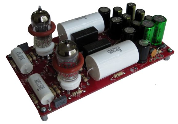
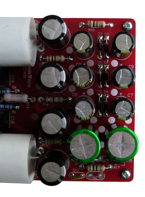
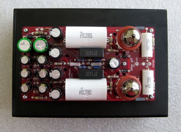
Here is what the previous version's power supply looked like:
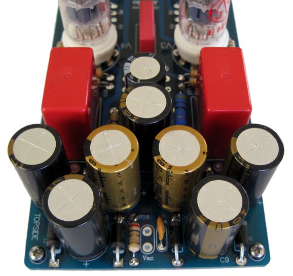
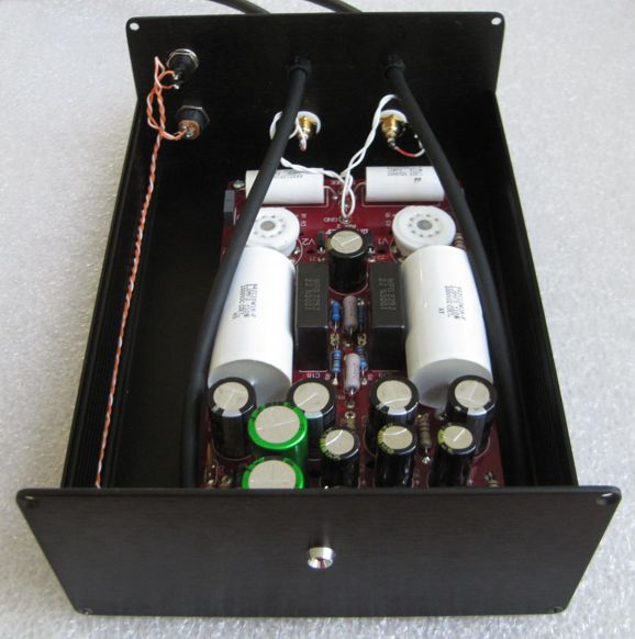
It held seven B+ capacitors, compared to the new revised version's twelve capacitors. Just like the previous version, revision2 requires a 12Vac power source. The key is AC, as in alternating current, not DC, as in direct current. (I hate emails asking if the 12Vdc switching power supply from their old printer will work; it won't; it can't.) I like using a 12Vac 24VA wallwart, but 12Vac secondary on a power transformer will also work well.
The previous version was 3.6 by 7 inches, so the increase in size is modest, but it is enough to allow bigger coupling capacitors. The CDE 1kV coupling capacitors I used are 2 by 1.2 inches.
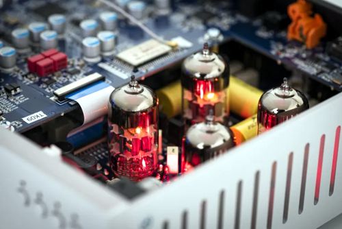
Even the circuit received a few small modifications to improve the PSRR. Who would want a 12Vac ACF? Anyone who needs a vacuum-tube unity-gain buffer and wishes to avoid the hassle of high-voltage power transformers and the danger of dealing with raw wall voltages. Moreover, many modern HiFi systems simply do not need any extra gain, as most modern signal sources, CD players, DACs, streaming-music devices, already provide enough gain to drive a power amplifier to full power. Well, why not go passive then, forgoing any active device? You can, but I built many passive line-stages, some with insanely expensive passive parts, but I have never been pleased—long term. The initial pleasure soon fell away, as I perceived an odd disembodied sound that seemed rootless and insubstantial. I cannot figure out why less wasn't more, but it was just less. Instinctually, passive seems the better approach (how could it be otherwise?), but my ears disagreed and won the argument. In addition, many want to interpose some vacuum tube warmth between their DACs and the rest of their system, which explains why the high-end Austrian company, Pro-Ject, offers the RS2 DAC which holds four tubes inside.
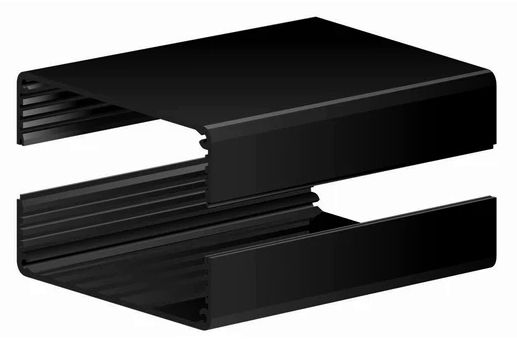
I own one of their Pre Box S2 Digital DACs, so I decided to add a 12Vac ACF to its output. Other than the PCB, the biggest hassle a solder slinger faces is the damn box. The days when local electronics stores existed, filled with Bud boxes and parts, are long over. Fortunately, I picked up a split-body, anodized, aluminum enclosure from the late Frys Electronics store 15 years ago for the reasonable cost of about $25. Today, things are no so reasonable, as the same box cost $55.30. It's made by Context Engineering and is 8.5" deep and 6.144" wide and 3.090" tall. Part number: 6016H-8.5B.
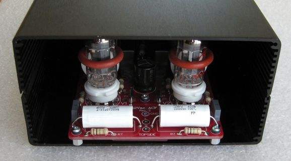
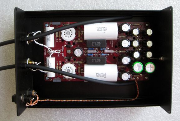
The next step was to see if the 12Vac ACF would fit inside.
Okay, it passed that test, but what about when it's loaded with tubes?
I had to use quarter-inch tall standoffs, but it fit. The alternative would have been to punch two holes in the top section or to have used low-profile tube sockets. I purposely, however, wanted to seal the tubes off from the external world. Why? All tubes (and transistors for that matter) are microphonic to some degree. I wondered how much fake reverb was resulting from the speakers sound hitting the glass envelopes. Sealed away, the tubes would be safe from the din. What about heat? The aluminum box's outside surface area is quite large and the black anodized surface radiates heat quite well, which explains why it is used on heatsinks. Thus, convection air current flow will wick the heat from the tubes and rub it on the inner walls of the box. The ACF runs warm, but not crazy hot, especially with the 12AU7 (JJ ECC802) tubes I used. Using ECC99 tubes would, however, double the dissipation. The two end panels are made of aluminum sheet, which is easy enough to drill.
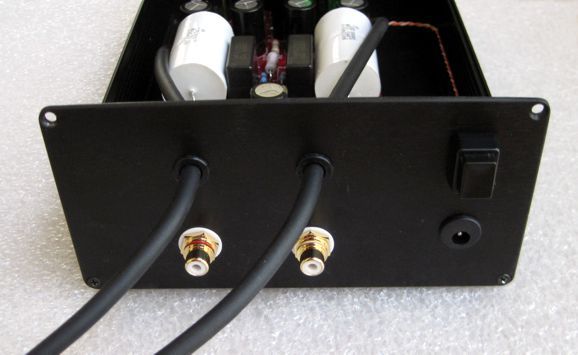
At the bottom, we see a power connector jack and a simple push-button switch, along with the tightly twisted wires that carry the 12Vac to the PCB. Note how the wires hug the bottom corner, the preferred place to prevent hum. Two input RCA jacks send the signal to the 12Vac ACF, while two lengths of microphone cable relay the signal out of the ACF, each terminated with an RCA plug.
Why not use an additional pair of RCA jacks? Two reasons" I hate RCA jacks and I wanted to apply two fancy techniques to the cables. The front panel only holds a single LED indicator light. (I used a 47k resistor in series with the LED to create softly dim light.)
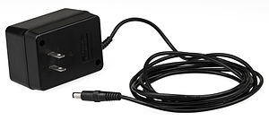
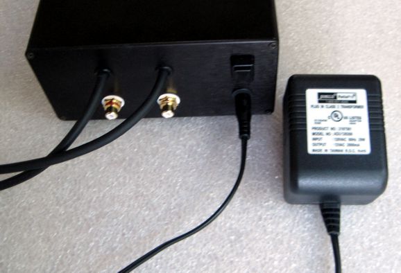
I don't want to leave out the wallwart power supply transformer, so here it is.
Okay, the big question is how does sound? Well, I am the last person you should ask. Why? Would you ask a mother if her baby was beautiful? In addition, I broke my first rule: NEVER make more than one change at a time—otherwise, you will have ZERO idea what change was actually responsible for the change in sound. My project held two changes: the new 12Vac ACF and the fancy-design interconnects. Well, having made that disclaimer, I thought it sound fabulous, but then I would. (It turns out, however, that I am capable of sonic self-deception for only about five to ten minutes. Thus, if after an hour of listening I am still happy, I will remain happy.) Nonetheless, I am going to try this setup at a friend's place and see and hear what he thinks. (A quick update, I brought it over and heard it in his system. I heard the same tube magic I had heard on my system. Definitely an improvement in sonic stage width and tone. The unit has found a new home. I will build another one, but with a few changes, such as an input selector switch and stepped attenuator. a unity-gain line-stage in other words.) The new 12Vac ACF Rev 2 is available at the GlassWare webstore now. You can get just the PCB or PCB with the parts kit. The wallwart power supply transformer I used is available at jameco.com. Happy listening.
Even More Diamonds
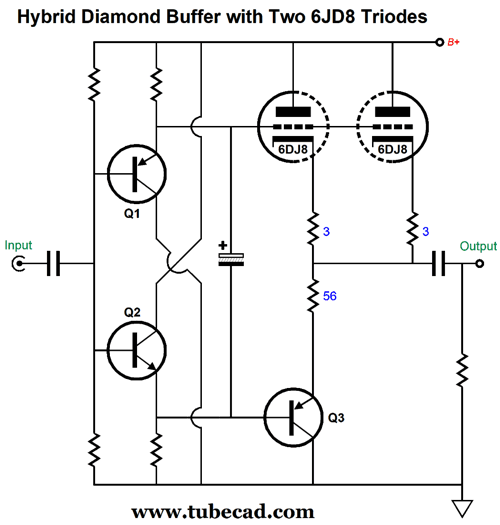
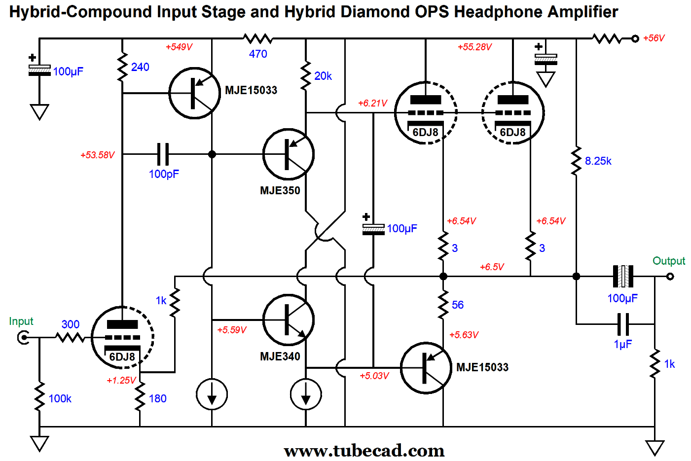
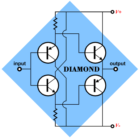
The 56-ohm emitter resistor ensures equal current swings from transistor Q3 and the two triodes. Note that no B+ voltage was specified and many of the parts values are missing. Let's change that, but first let's look at a simple hybrid compound circuit, as we will use the circuit to create signal gain and to drive the hybrid diamond.
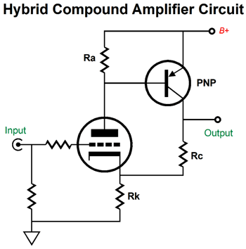
The triode drives the transistor; the transistor sets the triode's idle current. Unlike a tube, a transistor has a sharply defined base-to-emitter turn-on voltage, usually about 0.4V to 0.7V. We makes use of this turn-on voltage as a free voltage reference of sorts, as the PNP transistor will strive to see a fixed base voltage relative to its emitter by adjusting its collector current to force the triode below it to conduct the requisite current to create the desired voltage drop across the plate resistor. If the triode sees a positive-going input signal, the triode's current conduction must increase, which will increase the voltage drop across the plate resistor, which in turn will further increase the transistor's current conduction, causing the triode's cathode voltage to raise to the level that mains the previous idle current. This negative feedback in a nutshell. Since the collector resistor, Rc, is in series with the cathode resistor, a varying current flow through this resistor will cause a varying voltage drop, which is where we gain. The larger in value that resistor Rc is, the more gain we get. Okay, here is the example circuit.
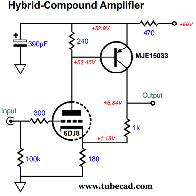
Note the crazy low B+ voltage. The gain realized is 1:6 (+15.6dB). With a 10k collector resistor, we get a gain of 1:41.9 (32.7dB). Of course, we also get a concomitant increase in distortion, as more gain means less negative feedback. As we plan on driving headphones, a gain of 1:6 is plenty. The next step is to couple the hybrid compound gain stage to the hybrid diamond output stage.
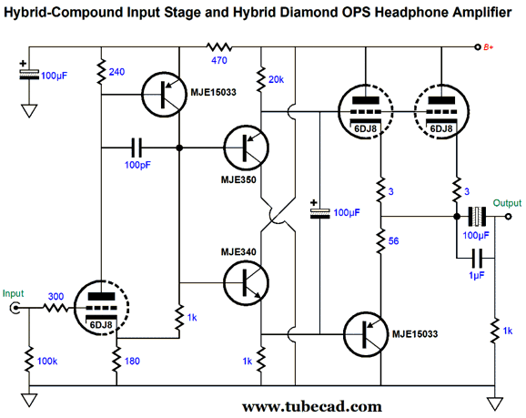
The 100pF capacitor was added to prevent peaking at ultra-high frequencies, as it imposes a local negative feedback loop at those frequencies. This circuit works, but not as well as it could, as the negative feedback loop only extends to the compound gain stage's output, not the amplifier as whole's output.
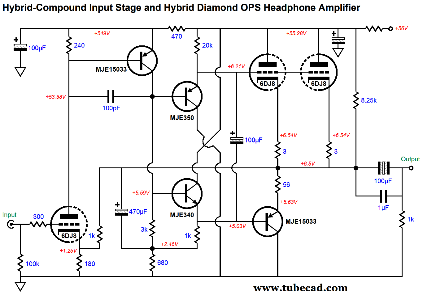
Now, the negative feedback loop extends to output, but not all the way past the output coupling capacitor, as the input triode's cathode voltage would leak out into the headphone driver. Not good. The two added constant-current sources improve performance substantially, but at the cost of added complexity. The sneaky workaround is to create faux constant-current sources.
The added 470µF capacitor that attaches to the output bootstraps the 3k and 1k resistors, effectively making appear much larger in resistance. The 8.25k resistor that spans from the output to the B+ voltage is there to provide a matching current draw to the 1k negative feedback resistor. The final step is to add many more triodes in parallel, as we hope to drive low-impedance headphones along with high impedance headphones.
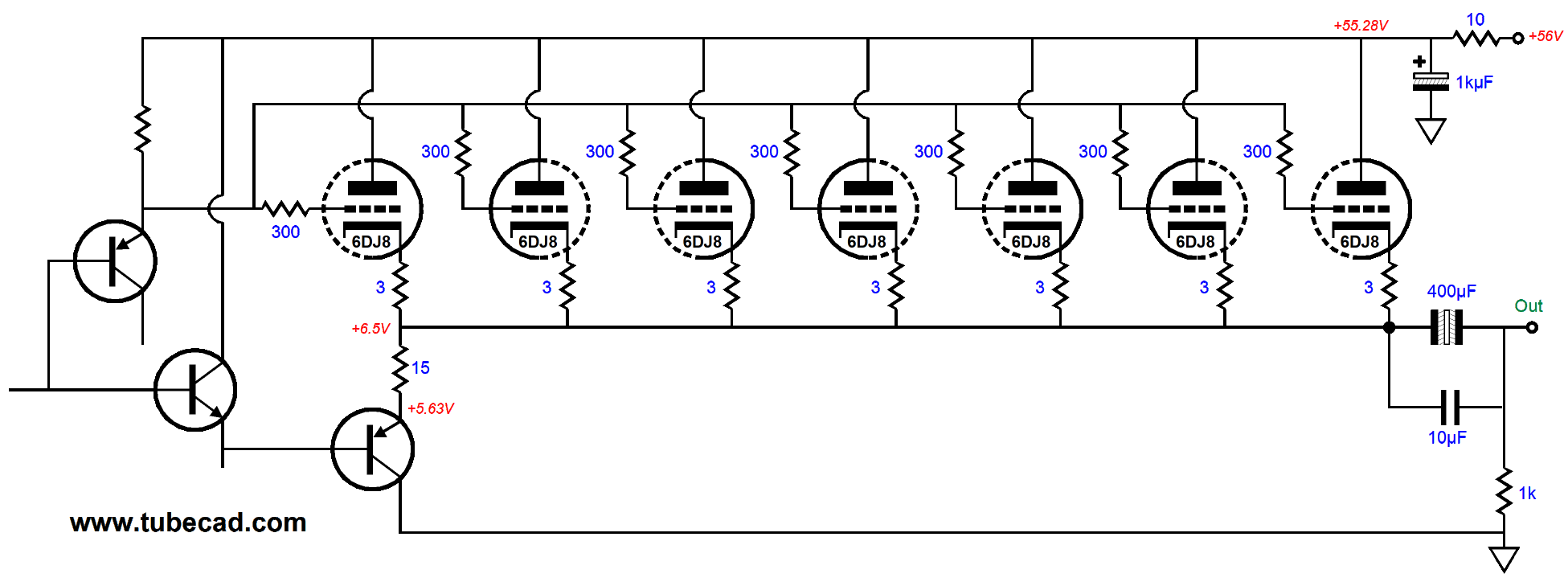
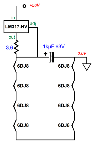
This is only the output stage. The seven 6DJ8 triodes in parallel are enough to drive 32-ohm headphones—even with the crazy low B+ voltage of only 56Vdc. Speaking of the B+ voltage, my idea is that we could use a 56Vdc switching tabletop power supply to power the hybrid headphone amplifier. How would we power the heater elements? Think Christmas-tree lights. We place all eight heaters in series and use an LM317-based constant-current source to deliver a fixed current flow of 347mA.
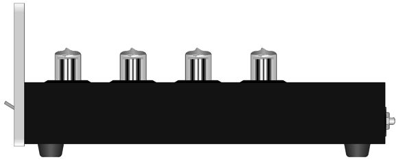
The 1kµF capacitor will ramp in voltage in a fairly linear fashion due to the constant-current source. (In the absence of the heaters, the charging up to voltage would be truly linear.) All of which will help extend tube life, as the usual harsh slamming on of heater voltage is not possible with this circuit. Remember that a cold heater presents a far lower resistance than a hot heater, which usually results in huge current inrush, which hurt the heater element over time. Okay, just imagine a small extruded aluminum enclosure with eight 6DJ8 in two rows of four tubes, all glowing—phalanx of glass. Too sweet for words, so a picture is needed.
Yes, it's my V8 concept all over again.
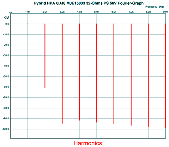
Each channel's seven output tubes draw a total of 59 mA. (By the way, do you get a small thrill when you encounter a large prime number as I do? The next primes are 61, 67, 71, 73, 79, 83, 89, 97…) This means each 6DJ8 triode draws 8.4mA, which implies a dissipation of about 400mW per triode, but a dissipation of over 6W for the entire output stage. What's more, the heaters will draw either 0.3A or 0.365A, which against the 56Vdc B+ voltage adds either 16.8W or 20.44W of heat dissipation to the total. In short, this little hybrid OTL will run hot. Fortunately, the external power supply helps mitigate heat substantially. Okay, how well does this design work in SPICE? The PSRR at 100Hz was a respectable -59dB, which is very good but not really that important with a switching power supply that runs at 50kHz or higher. At 50kHz, the PSRR was an impressive -111dB. (Sure 111 looks as if it is prime, but it isn't as 3 and 37 are its divisors, but is a perfect totient number and palindromic number.) With a 470µF output coupling capacitor and 32-ohm load, the bandwidth extends from 10Hz to 440kHz. The THD in SPICE simulations with 1Vpk at 1kHz into 32-ohms was 0.094%.
Note the strong 2nd and weak 3rd harmonics. The peak output-voltage swing into 32 ohms was 4Vpk, which translates into 250mW; the THD climbed to 0.48%. The peak output-voltage swing into 300 ohms was 5Vpk and the THD dropped to 0.027%. The output impedance was less than one ohm! It's amazing what can be done with a B+ voltage of only 56Vdc.
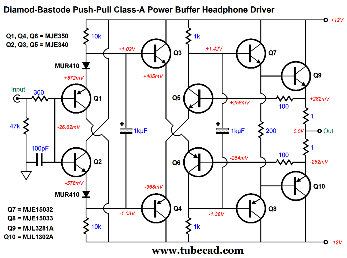
One Last Diamond
This unity-gain power buffer runs in strict class-A, as the output stage idles at 282mA, twice what the typical solid-state power amplifier's output stage idles at. Since it is push-pull output stage, we can expect twice the idle current flow as the peak output current swing, namely 564mA, which against a 32-ohm load equals 18Vpk, something the ±12Vdc bipolar power supply rails cannot support. Indeed, all we are aiming for is a clean 8Vpk of peak output voltage swing, which into a 32-ohm load equals 1W (1,000mW). The output stage, from transistors Q5 through Q10, enjoys an internal negative feedback loop that keeps the distortion low and establishes auto-bias of the output transistors. Speaking of the output transistors, they are big robust output devices that are found in super expensive power amplifiers. One way to look at it is that the diamond circuit is merely a buffer to drive transistors Q5 and Q6, which are the gain stages that control the emitter follower output stage—with 100% negative feedback returned to their bases. The 1kµF capacitor that bridges their collectors unifies their output signal. With 4Vpk of output voltage swing into 32-ohms, the THD was below 0.01% in SPICE simulations. As long as transistors Q1 through Q6 are kept away from the remaining transistors, the auto-bias works well. In SPICE simulations, a sweep of temperature of 100 degrees Celsius resulted in an increase in idle current of only 5mA.
Music Recommendation: Ma Rainey's Black Bottom
//JRB
Very few can imagine just how much hard work is required to make one of my posts. If you have any sort of inkling or intuition of what is involved, please think about supporting me at Patreon.
User Guides for GlassWare Software
For those of you who still have old computers running Windows XP (32-bit) or any other Windows 32-bit OS, I have setup the download availability of my old old standards: Tube CAD, SE Amp CAD, and Audio Gadgets. The downloads are at the GlassWare-Yahoo store and the price is only $9.95 for each program. http://glass-ware.stores.yahoo.net/adsoffromgla.html So many have asked that I had to do it. WARNING: THESE THREE PROGRAMS WILL NOT RUN UNDER VISTA 64-Bit or WINDOWS 7 & 8 & 10 or any other 64-bit OS. I do plan on remaking all of these programs into 64-bit versions, but it will be a huge ordeal, as programming requires vast chunks of noise-free time, something very rare with children running about. Ideally, I would love to come out with versions that run on iPads and Android-OS tablets.
//JRB |
|
I know that some readers wish to avoid Patreon, so here is a PayPal button instead. Thanks. John Broskie
John Gives
Special Thanks to the Special 77 To all my patrons, all 77 of them, thank you all again. I want to especially thank
I am truly stunned and appreciative of their support. In addition I want to thank the following patrons:
All of your support makes a big difference. I would love to arrive at the point where creating my posts was my top priority of the day, not something that I have to steal time from other obligations to do. The more support I get, the higher up these posts move up in deserving attention.
Only $12.95 TCJ My-Stock DB
Version 2 Improvements *User definable Download for www.glass-ware.com |
||


| www.tubecad.com Copyright © 1999-2022 GlassWare All Rights Reserved |