| John Broskie's Guide to Tube Circuit Analysis & Design |
11 June 2022 Post 558
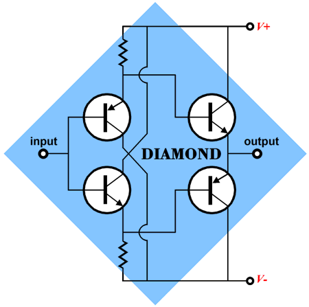
Diamond Input-Output Stage
In addition, it makes biasing the output transistors easy, as the output transistors directly couple to the input transistors emitters. Moreover, if the input and output transistors share the same heatsink, they thermally track each other, thereby auto-correcting for changes in temperature. In other words, as the base-to-emitter voltage falls with increased heat, the idle current remains constant, as bottom the input and output transistors fall in unison. This setup works best when the same NPN transistors and PNP transistors are used throughout.
And even better when transistors Q1 & Q3 and Q2 & Q4 thermally track each other, the result of close proximity on the heatsink. If the input and output transistors do not attach to the same heatsink, however, the auto-correcting fails. I have often used two heatsinks designed for TO-220 devices, so that I could mount one input transistor and its output transistor partner on either side of the heatsink.
In fact, I am amazed that they never made a diamond-circuit IC in the TO-200 package with seven pins that held only four transistors, as the thermal lag imposed by the heatsink could be sidestepped, as the input and output transistors would be intimately coupled inside the IC case.
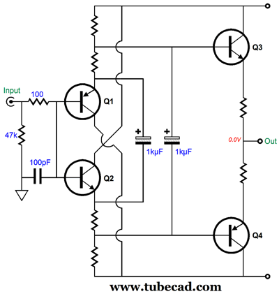
Such an IC would allow the user to add the desired resistors. In addition, we could get extra fancy. For example, bridging the two output transistor bases with a large-valued capacitor is a worthwhile modification.
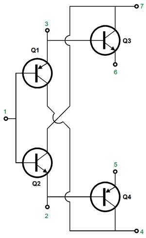
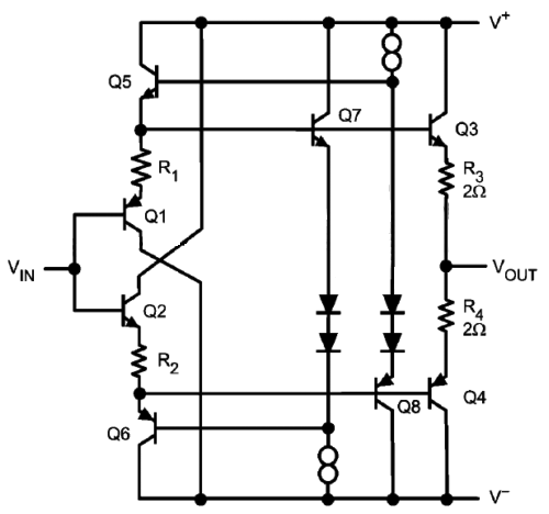
The capacitor effectively allows both input transistors to drive both output transistors at once, which lowers distortion, makes for larger output voltage swings, and slightly improves the PSRR figure. Not bad for a 50-cent investment. Obviously, big electrolytic capacitors cannot be included in the IC package. Even if we could, we wouldn't do so, as heat kills electrolytic capacitors. The LMH6321 IC contains a fancy diamond buffer. Since big electrolytic capacitors cannot be included, it opts for more transistors and diodes, building a symmetrical, push-pull input stage to drive the output transistors Q3 & Q4 to full output.
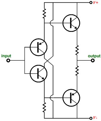
(The actual circuit is more complex, but I cut out extra protection diodes to make the topology more easily comprehended.) The problem with the diamond's input stage biasing of the output transistors is that bias voltage—the result of the output transistors drawing some current through their bases—is only a tiny bit larger than the output transistor base-to-emitter voltage, which creates a tiny voltage differential between the two output transistor emitters. Ideally, we would something like a 200mV voltage differential between the emitters, not the 14mV we get with the diamond. The usual workaround is just to add two more resistors.
The bias voltage is increased by the voltage drop across the added resistors. Sadly, this workaround presents its own problems. For example, if the power-supply rail voltage fall, so will the bias voltage, which in turn causes the idle current to fall. Conversely, if the power-supply rail voltage increases, so, too, increases the idle current flow. What we really need is a low-voltage voltage reference, which are not made. Well, at least they are not made as voltage reference ICs. We can, however, use a special kind of rectifier to function as a voltage reference with a truly low voltage drop; i.e. Schottky barrier rectifiers (aka, hot-carrier diodes). These rectifier offer a fast turn-on and a very low switching-on forward-bias voltage, as little a quarter that of a typical rectifier such as the 1N4007.
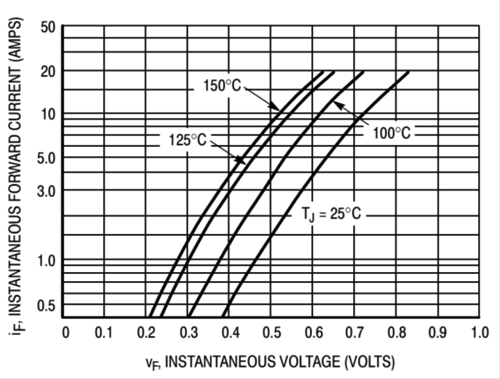
The graph shows the turn-on voltage for an MB1060 Schottky rectifier in the To-20-AC package. The graph's Y-axis starts at 0.4A. At 30 degrees centigrade and with 1mA of current flow, the forward-bias voltage is only 0.223V. This may not seem like much voltage, but compared to the diamond's output-transistor emitter voltage of 7.5mV, it's huge, about 30 times larger. With two MBR1040 rectifiers in place, the output transistor's emitter voltage climbs to 130mV with an idle current flow of 130mA; in other words, with 1-ohm emitter resistors in place.
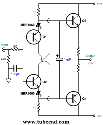
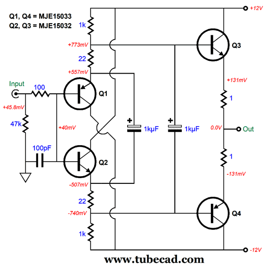
The 100-ohm resistor and 100pF capacitor are there to impose a low-pass filter in the input signal, which will prevent peaking at some ultra-high frequency. The MB1060 Schottky rectifier is fairly cheap, less than a dollar. (Well, I should say that it is less than a dollar as of June 2022, as who knows what it will cost in a year or two.) On the other hand, if the circuit is powered by a regulated bipolar power supply, we can get away with the extra resistor solution, but with one alteration.
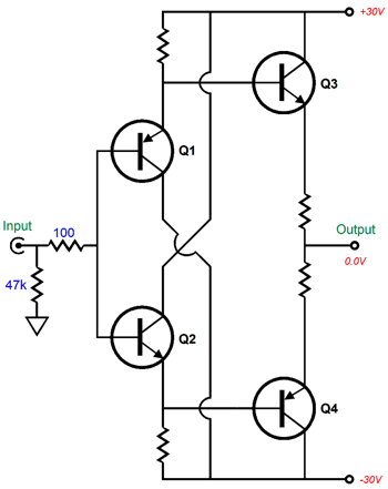
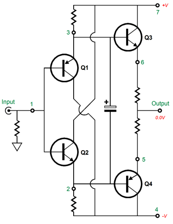
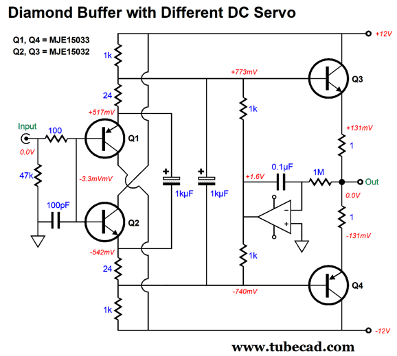
Note the extra 1kµF capacitor that bridges Q1 and Q2 emitters. This added capacitor helps lower distortion slightly. I ran SPICE simulations on the stability of the idle current with changes to the transistor temperature. The results revealed a slight negative relationship to increased temperature, which is close to ideal. An increase of 100 degrees centigrade (huge, insanely huge) resulted in a decrease in the output transistor idle current of only 4.6%, going from 131mA to 124.9mA. Mind you, this was with the same NPN and PNP transistors used throughout. In my SPICE simulations, I used the following circuit.
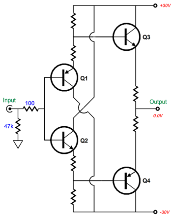
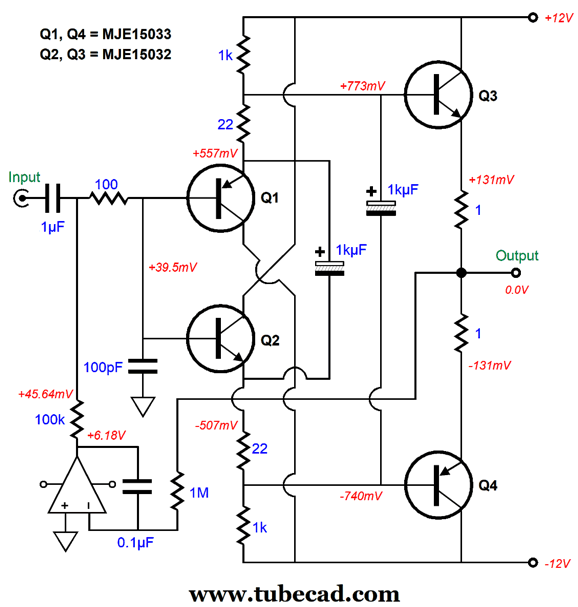
Bear in mind that transistors Q1 and Q3 must be mounted close together on the same heatsink, as must transistors Q2 and Q4, although they can be mounted on a different heatsink. If dissimilar input and output transistors are used, the thermal tracking will be a crap shoot, with an undesirable positive relationship to increased temperature likely. In fact, with the use of the MJE340 and MJE350, I witnessed a huge positive relationship to increased temperature. We can further improve this unity-gain power buffer by adding a DC servo to eliminate a DC offset voltage at the output. Note how in the circuit shown above I had to inject a 45.8mV DC offset at the input to force the output to 0.0V.
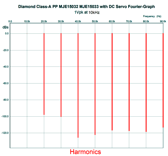
The OpAmp should hold a FET input stage. The 1µF input coupling capacitor might seem excessively large, but it allows low-frequency bandwidth down to 5Hz. Unlike triodes, the input transistors present a relatively low input impedance (about 47k in this circuit), so the 100k resistor is in parallel with the 47k impedance. The input low-pass RC filter (100-ohm resistor and 100pF capacitor) at the input limits the high-frequency bandwidth to 1MHz and prevents high-frequency peaking. How well does this diamond buffer perform? Here is the SPICE-generated graph for 1Vpk of output voltage at 10kHz into a 32-ohm load. (I used a 100µF input coupling capacitor to avoid tripping up the Fourier analysis because of phase shift.)
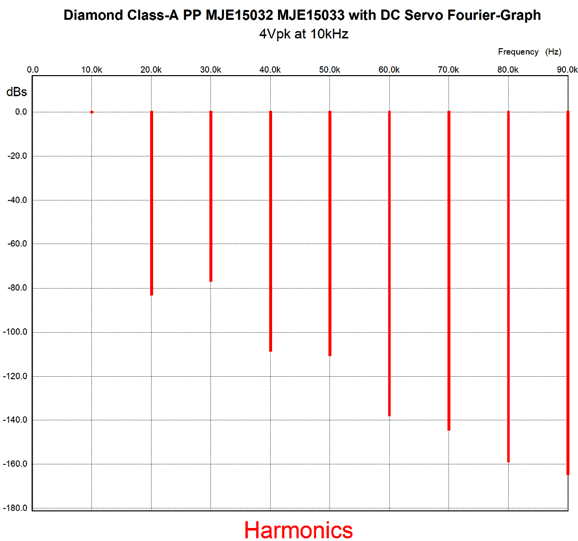
The distortion is quite low due to the high idle current (131mA) and the class-A operation. The THD is well below 0.01%, approaching 0.001%. The next test was at 4Vpk.
Surprisingly good. In fact, I prefer this set of harmonic plots to the previous one, as the higher harmonics are further suppressed. With 8Vpk of output, 1 watt of power into 32-ohm headphones, the THD rises to about 0.1%. Not at all bad for a negative-feedback-free design.
Alternative DC Servo for Diamond
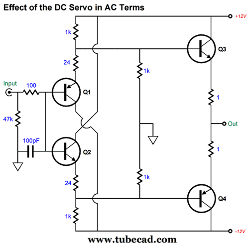
The OpAmp compares the output DC voltage to the ground and swings its output voltage in the opposite direction of any DC offset through the two 1k resistors. I ran some SPICE simulation and the circuit worked, but I noticed a change in the distortion harmonics, with some harmonics improving, while others worsened. This makes sense, as the two 1k resistor are effectively grounded at their connection to each other, as the OpAmp puts output a low output impedance and steady DC voltage at its output.
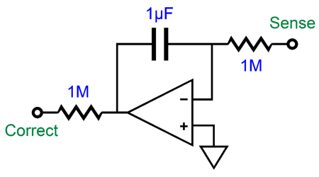
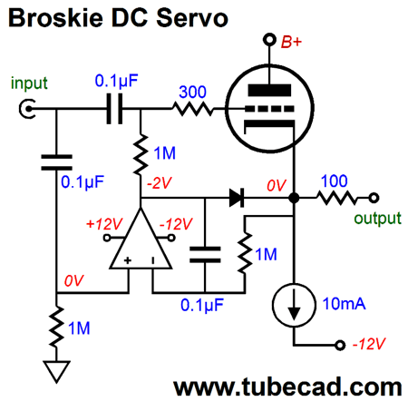
It didn't take long for me to realize that this circuit would benefit from using my Broskie DC servo instead.
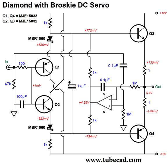
The DC servo's output follows the input signal, which in the circuit above prevents the diode from becoming forward biased under normal operation, but allows the diode to engage when the triode is cold and not yet conducting or is missing from its socket. Applying the servo to the diamond is easy enough.
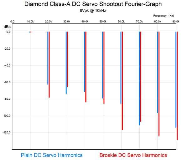
The two 1k resistors remain, but this time the OpAmp's output follows the input signal, so the resistors no longer impose a drag on the input transistor emitters. I performed a shootout in SPICE, and here are the results.
I am not sure which I would call a clear winner, as Broskie DC servo won the 2nd, 4th,5th, 6th, 8th, and 9th harmonic battle, but it lost the 3rd and 7th (although by a tad). In actual listening shootout, the plain DC servo might win due to its higher 2nd and lower 3rd.
More Than One-Carat Diamonds
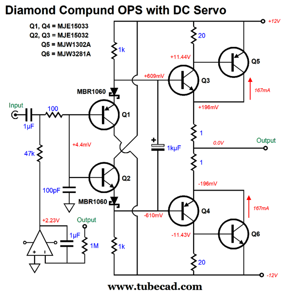
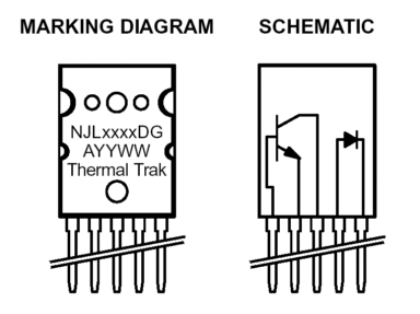
Transistors Q5 & Q6 (MJW1302A and MJW3281A) are found in premium solid-state power amplifiers and come in the big TO-247 packages. Here they are being employed in a power buffer for driving low-impedance headphones. The compound topology is an auto-bias design of sorts, as the main two output transistors, Q5 & Q6, are controlled by the driver transistors, Q3 & Q4. Thus, it little matters how hot the main output transistors become, as long as the driver transistors, Q3 & Q4, remain at a constant temperature. Each of the 1-ohm emitter resistors see a 196mV voltage drop, so the idle current is 196mA, with the output transistors, Q5 & Q6, drawing the bulk of the current. The DC servo at the input prevents a DC offset voltage at the output. For the best results, transistors Q1 & Q3 and Q2 & Q4 must tightly thermally track each other, which requires close placement on the heatsink. The MB1060 Schottky rectifiers, in contrast, should be located away from the heatsink, as we do not want them to become hot. The next design is meant to drive speakers, not headphones, although it could easily drive headphones.
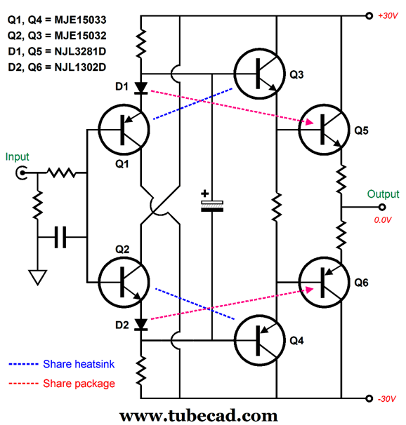
This design exploits the new transistor types that contain a free-floating rectifier, namely, the NJL1302D and NJL3281D.
My fingers grow tired, so I will quote myself from post 479:
We can use the internal diodes, along with the diamond's self-correcting immunity to temperature shifts, to create an auto-bias scheme. Once again, transistors Q1 & Q3 and Q2 & Q4 must tightly thermally track each other, which requires close placement on the heatsink, and should be of the same kind—no mixing and matching allowed. As the output transistors, Q5& Q6, heat up, their base-to-emitter voltage falls, but then so, too, does the diode's voltage drop, so the idle current remains fairly constant. Okay, let's flesh out the design.
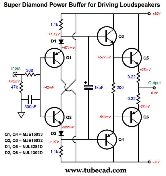
Note that the bipolar power-supply rail voltage have gone from ±12Vdc to ±30Vdc. The output transistor idle current is equal to 0.027V/0.22-ohm or 123mA. The point behind this design is to exploit two thermal-tracking systems. The first is the diamond topology based using identical NPN and PNP transistor for Q1 through Q4. The second is using NJL1302D and NJL3281D transistors and their internal diodes. (The assumption is that the diamond portion of the buffer share the same heatsink, or that at least Q1 and Q3 share the same heatsink, just as Q2 and Q 4 do.) I ran a SPICE simulation that varied the temperature for all the parts at once from 25° to 125° centigrade (77° to 257° Fahrenheit) and then monitored the change in the output transistors' idle current. Here is the amazing result.
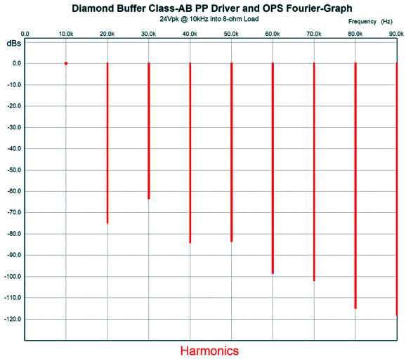
Far, far better than I expected. Note the initial decline and the mild increase beyond 75° centigrade. The next big test is distortion at full output.
The THD is about 0.1% and the output power is 36W into an 8-ohm load. It looks a tad ragged, but it still cascades nicely. Remember, the idea behind all these power buffer designs is that a tube-based hot line-stage amplifier will drive the solid-state power buffer to full output. In other words, we can expect the tube 2nd harmonic to undo some of this design's attenuated 2nd harmonic. The big question is: Will this work in reality? Only a test with real transistors and real heatsinks will deliver the answer. If it does work, this setup could prove amazingly useful.
Music Recommendation: Jakub Józef Orlinski's Anima Aeterna I often wonder if the reason so few like classical music is due to poor audio playback. Few have ever heard a classical symphony performed live. In other words, classical music had to wait until technology caught up with it. In contrast, I remember thrilling to songs by the The Beatles and the Rolling Stones produced by the car's 6" speaker. Let me put differently: the real test of a high-quality stereo is not the ability to reproduce jet airplanes, gunshots, train whistles, thunder, but massed strings and massed voices. Jakub Józef Orlinski is a young (31 years old) Polish countertenor, break-dancer, and sometimes male model. Ah, to be young, handsome, and talented. He won the Gramophone Classical Music Award in the category of Young Artist of the Year. He does sing beautifully. The classical-music review website, theclassicreview.com, ended their review of this album with this two-word sentence: Urgently recommended. I concur.
//JRB
Very few can imagine just how much hard work is required to make one of my posts. If you have any sort of inkling or intuition of what is involved, please think about supporting me at Patreon.
User Guides for GlassWare Software
For those of you who still have old computers running Windows XP (32-bit) or any other Windows 32-bit OS, I have setup the download availability of my old old standards: Tube CAD, SE Amp CAD, and Audio Gadgets. The downloads are at the GlassWare-Yahoo store and the price is only $9.95 for each program. http://glass-ware.stores.yahoo.net/adsoffromgla.html So many have asked that I had to do it. WARNING: THESE THREE PROGRAMS WILL NOT RUN UNDER VISTA 64-Bit or WINDOWS 7 & 8 & 10 or any other 64-bit OS. I do plan on remaking all of these programs into 64-bit versions, but it will be a huge ordeal, as programming requires vast chunks of noise-free time, something very rare with children running about. Ideally, I would love to come out with versions that run on iPads and Android-OS tablets.
//JRB |
|
I know that some readers wish to avoid Patreon, so here is a PayPal button instead. Thanks. John Broskie
John Gives
Special Thanks to the Special 87 To all my patrons, all 87 of them, thank you all again. I want to especially thank
I am truly stunned and appreciative of their support. In addition I want to thank the following patrons:
All of your support makes a big difference. I would love to arrive at the point where creating my posts was my top priority of the day, not something that I have to steal time from other obligations to do. The more support I get, the higher up these posts move up in deserving attention.
Only $12.95 TCJ My-Stock DB
Version 2 Improvements *User definable Download for www.glass-ware.com |
||


| www.tubecad.com Copyright © 1999-2022 GlassWare All Rights Reserved |