| John Broskie's Guide to Tube Circuit Analysis & Design |
|
15 may 2020 Post 503
Updating Error-Correction Schematic
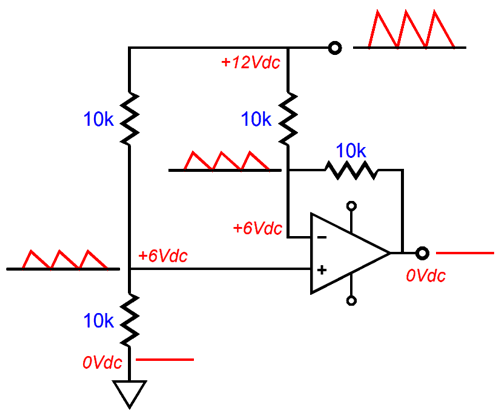
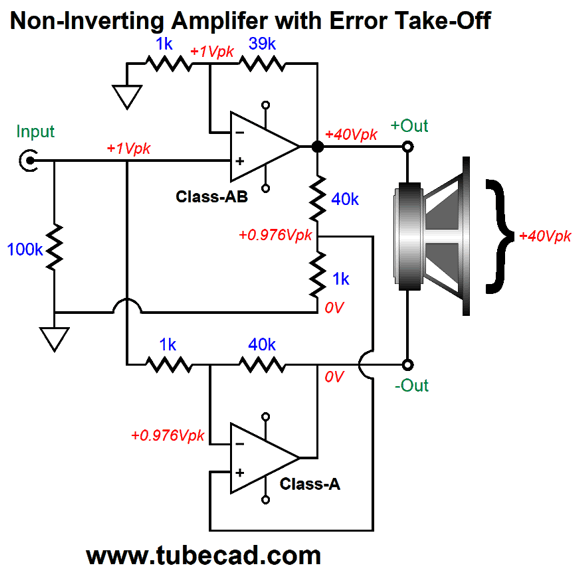
In other words, enough time had passed for me to give my own writing what I give the writings of others, namely the same series of questions: what is being claimed? What proof, evidence, or logic is being provided? Could it be otherwise? In other words, what if we flip the conclusion? What if we go to extremes, does it still hold true? (I was born hyper critical, which explains why I cannot watch TV.) I was pleased not to encounter too many objections from my now disinterested mind. (By the way, "disinterested" does not mean uninterested, i.e. not caring; instead, it means not having a stake in the outcome. But this wasn't always so, as originally they meant the reverse. A word's meaning often changes with time, sometimes becoming its opposite. "Let" used to mean forbid or obstruct, as it often does in the King James Bible. Nonetheless, now that we do have the modern distinction between "disinterested" and "uninterested," a useful distinction, let us maintain it.) Then I came to the part in that post that stated that the input signal must appear at the same magnitude at the error-correcting amplifier's output. Really? Why? Of course, based on the resistor values I had used, this had to be the outcome—but what if we altered the values? Essentially, the bottom amplifier, the error-correcting amplifier, is a power differential amplifier. It compares two signals and delivers only the difference between signals at its output, albeit in an amplified form. In other words, given identical signals (i.e. zero distortion) the output should be zero; in the case of an error-correcting amplifier, 0V. Here is an example of a differential amplifier rejecting both ripple and the 12Vdc voltage at its output.
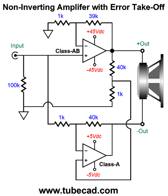
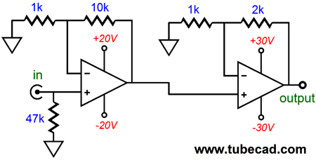
The math behind my resistors values was close, but not on the mark. Here are the revised values.
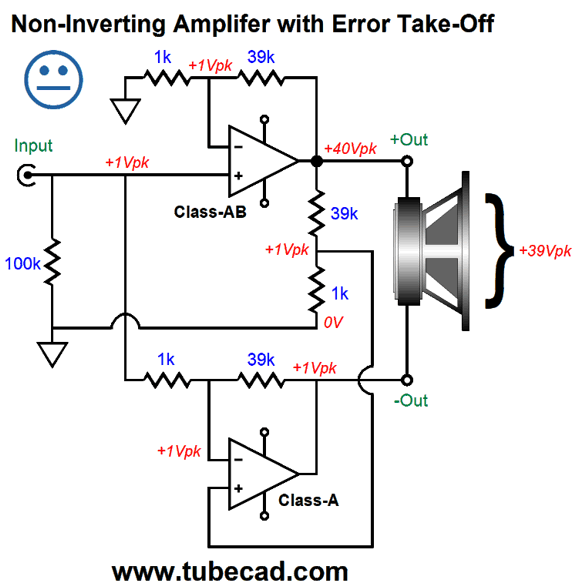
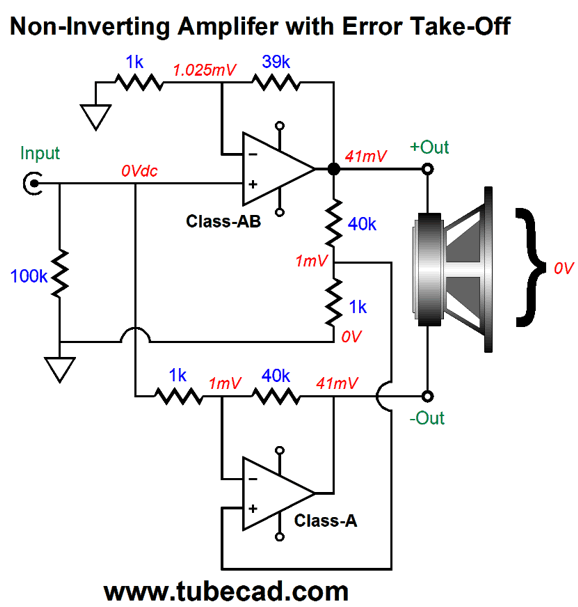
Apparently, I failed to realize the slight gain increase with the non-inverting setup of the top amplifier compared to the original Sandman inverting topology. In other words, given the same negative feedback resistor values, the non-inverting setup of the top amplifier will yield a gain 1 greater than the inverting setup. For example, with 1k and 39k, the non-inverting setup of the top amplifier delivers a gain of 40; the inverting setup, 39. After replacing two 39k resistors with two 40k resistors, the bottom amplifier's output no longer produced the input signal at its output.
No doubt some of you are wondering about the 40k value, as they don't make a 40k resistor, not even in the E192 range of 0.1% resistors. They do make a 40.2k resistor, but I wouldn't use it; instead, I would use two 20k resistors in series. In fact, I would hand measure and match all the resistors. Why? Much like an OpAmp-based instrumentation (or differential) amplifier, resistor matching is essential. In fact, when you buy an instrumentation IC it often includes the critically matched resistors, which were laser trimmed during its making. The schematic shown above assumes no distortion from the top amplifier. If there were distortion, it would also appear at the bottom amplifier's output, equal in amplitude and in phase. Let's use the example of the top amplifier presenting a DC offset, which is a form of distortion, albeit DC distortion.
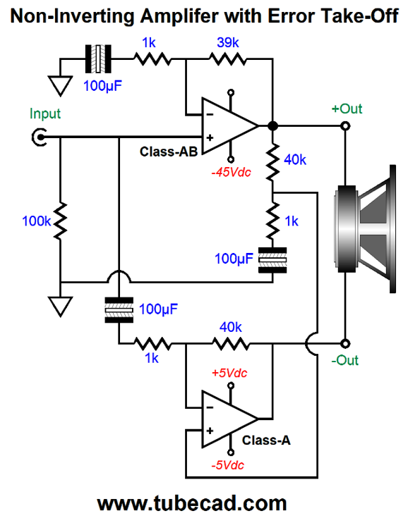
Okay, the signal's phase is key here. Note that neither of the two negative feedback loops nor the two-resistor voltage divider held a capacitor terminating into ground. This is rare. Most power amplifier hold at least a terminating capacitor at the end of the feedback resistors. This capacitor prevents the amplifier from amplifying DC offset voltage present in the input signal; in addition, it allows the amplifier's full open-loop gain to power the negative feedback in reducing the amplifier's own intrinsic DC offset. In fact, many, if not most, commercially made power amplifiers also hold an input coupling capacitor. For a brief while during the late 1980s, DC throughout was a fad, mostly in Japan. Okay, how do we incorporate terminating capacitors in this design?
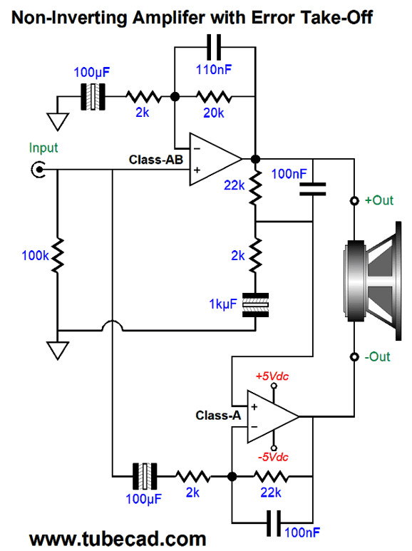
The next potential obstacle is the high-frequency limiting capacitor we often find across the main negative feedback resistor. Almost all solid-state amplifiers hold this capacitor, as its inclusion improves the amplifier's phase margin, thereby making it more stable at high-frequencies. That is all well and good, but adding the capacitor will undermine the error-correction scheme, as the bottom amplifier would strive to reintroduce the attenuated high-frequencies, as the low-pass filtering would be viewed as just another form of distortion to be eradicated. The workaround is to add two more capacitors.
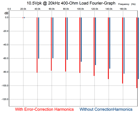
Now, the two negative feedback loops and the single voltage divider share the same high-frequency response. (note how the capacitor values match the resistor it shunts.) The two-resistor voltage divider, however, goes far lower, due to its much larger terminating capacitor. In SPICE simulations, this ended up lowering distortion even further. So, why bother using a terminating capacitor on the two-resistor voltage divider? If we DC coupled the resistor string to ground, then the bottom amplifier would not null the top amplifier's DC offset at its output. Okay, so how well does this error-correction scheme work? In SPICE simulations, the results were good, maybe too good, as I am not sure that I trust Burr-Brown OpAmp SPICE models. Nonetheless, I ran the Fourier harmonics test at 20kHz and 10Vpk into the OpAmp's low-impedance load limit (effectively at its current limit). The more I thought about it I realized that I should use dissimilar OpAmps, an old poor-performing OpAmp in the top position and new high-performance OpAmp in the bottom position. Okay, I re-ran the simulations with an AD823 in the top position and an OPA2107 in the bottom amplifier position. The test frequency was 20kHz and the top amplifier put out 10.5Vpk into 400 ohms, which pushed the AD823 to its limits and its highest distortion before it actually clipped. Here is the Fourier graph that shows the improvement.
Just about a 20dB improvement for all harmonics. The next question is could this error-correction scheme be applied to a tube-based amplifier? A super interesting question isn't it? With OTL amplifiers, I am inclined to think no way. Why not? Say the top OTL amplifier put out 100W into 8-ohm loudspeakers. This implies peak current swings of 5A, which the bottom error-correcting amplifier would have to sink, as it functions as a virtual ground. With the solid-state version, the bottom amplifier could run under tiny bipolar power supply voltages, say +/-5Vdc. This is not an option with tubes. Okay, what about transformer-coupled tube amplifiers? Maybe. Building a 100W push-pull tube amplifier is fairly easy. Designing a super-low-distortion low-wattage bottom amplifier would prove far more difficult. On the other hand, the bottom amplifier would only have to swing a volt or two, albeit at 5A. One volt peak swing at 5A peak current swing equals only 2.5W. So, the bottom amplifier need only put out 3W or so—but at 5A peaks. This requires a huge winding ratio between primary and secondary. For example, if the winding ratio were 50:1, a single-ended bottom amplifier need only idle at something over 100mA, yet be able to put out 5A swings at its secondary. By the way, a winding ratio of 50 implies an impedance ratio of 2500:1; thus, if the output triode's plate impedance were 800 ohms, the output impedance at the secondary would equal 800/2500, or 0.32 ohms. And one volt of output voltage swing would require 50V of plate voltage swing. In other words, we could get away with a relatively low B+ voltage, but high idle current. The bigger problem is that no one makes a small output transformer with a 20k primary impedance, as far as I know. In other words, a custom output transformer would be needed. In addition, we would need an all-out effort to get the bottom amplifier's distortion sufficiently low. Then there is the issue of designing a differential input stage, as the entire bottom amplifier would function as a power differential amplifier. Moreover, we can add the squirreliness of output transformers and troublesome phase shifts to the list of hard problems to solve. Still, the dream of a 100W power amplifier that sounded like a high-quality single-ended amplifier is enchanting.
Two-Position Auto-Bias Single-Ended OPS
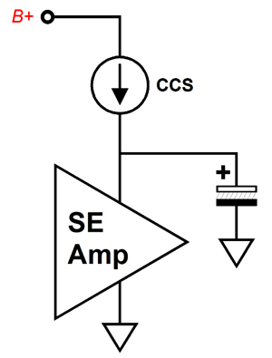
In post 409, I stood this arrangement on its head by moving the constant-current source from the cathode and ground to the top of the output transformer and the B+ voltage.
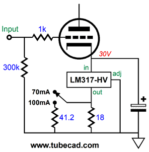
A Zener diode replaces the cathode resistor and the constant-current source establishes a fixed current flow by varying the B+ voltage that single-ended output stage sees. We still get auto-biasing, but we also gain a fantastic feature—namely, insanely good PSRR. The constant-current source shields the single-ended amplifier from the power-supply noise, much as a big choke would. Is this important? Dang yes. I once modified a friend's single-ended amplifier by adding some Aikido mojo techniques and cleaning up the grounding scheme. The result was a reduction of hum at the output from 30mV down to below 1mV (my voltmeter could not read below 1mV). He was not just happy, he was deliriously ecstatic. A huge opera fan, he called me up, proclaiming the great improvements in the singing. He delivered a long list of Italian adjectives that described the texture and tonality of singing, none of which I knew. Although we spoke on the phone, I could easily imagine his agitated hand gestures. I remember him saying that I had greatly improved the spinto and the squillo. I still do not know what "spinto" and "squillo" means, but I do know that I had greatly improved the PSRR and he could now hear greatly improved spinto and squillo. Okay, now we can move on to today's topic: two-position dissipation. Often, we just want pleasant background music. This happened to me yesterday. I was busy working away on a tough problem. I selected an album from Amazon Music with a title like Soothing Saxophones, which turned out to be a fortunate choice, as the music was indeed soothing and pleasant, not intricate and challenging. At other times, we want excitement, desiring audio showcase quality and matching high volume levels. Two choices are often best. I know serious LP and book collectors, who must own two copies of their favorite LPs and books: one to store and preserve and one to enjoy without fear of wear or damage. One advantage to owning a 357 magnum pistol is that the gun will also fire polite wadcutter target .38 Special rounds, which kick far less. At parties, the standard procedure is to start with the good adult beverages and then move down in quality, as the crowd grows smashed. Well, not only do I understand these different modes of enjoyment, I want something like it in a power amplifier. When desiring background music, the amplifier should just loaf along, so why should its output tubes radiate heat as if it were blasting away? Thus, we have the compelling reason for two stages of dissipation, low and high. Low for background listening, high for showing off. With a grid-biased single-ended output stage, we could add a toggle switch that selected between two grid-bias voltages, say -30V for background listening and -20V for serious listening. The idle current falls in the first position and rises in the second; so, too, the output tube dissipation. But is such an arrangement possible with a constant-current source, either at the cathode or at the B+ voltage? With the cathode-bias version, where the constant-current source replaced the cathode resistor, we can select between two current-adjustment resistor values.
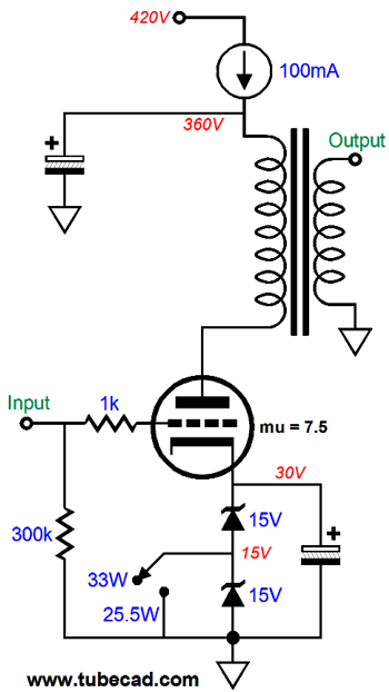
With both resistors placed in parallel, the idle current increases to 100mA. With only the 18-ohm resistor, the idle current falls to 70mA, and the plate dissipation decreases by 30% and the power output by 50%. Now, if we try applying this toggle switch to the constant-current source located at the B+ voltage, we have to deal with high-voltages, which might exceed the switch's voltage rating and, if nothing else, it makes for a nervous situation. Just imagine a 211 or 845 power amplifier with a B+ voltage of over 1kV. One workaround would be to use two Zener diodes in series, with the switch selecting between shorting one Zener to ground or letting both work in series.
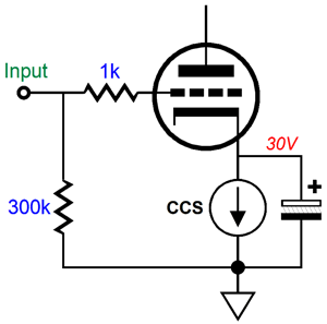
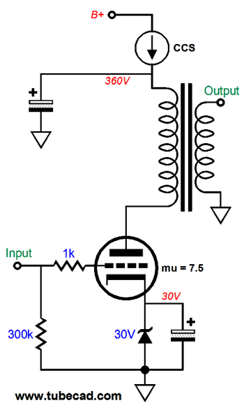
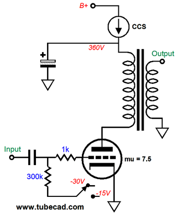
Normally, with a lower cathode voltage, we get a much higher idle current flow. In contrast, with the constant-current source located at the B+ voltage, the idle current is fixed, but the plate voltage is variable. If we lower the cathode voltage, the constant-current source will lower the plate voltage until the idle current restores to the fixed amount. The result is that the plate dissipation drops. Yes, I know it seems paradoxical. Here is a single zener and a B+ voltage constant-current source.
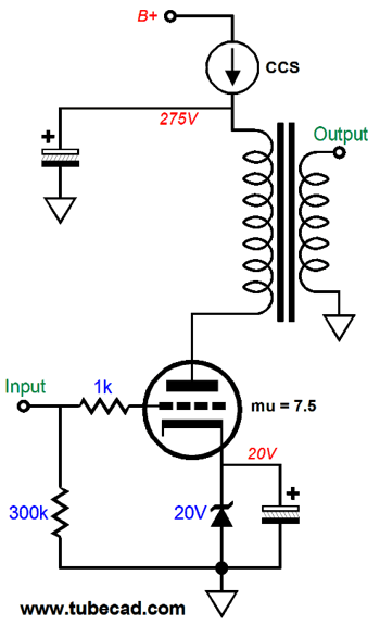
We assume that the output transformer's primary presents zero DCR, which is impossible. The cathode-top voltage equals 360V minus 30V cathode voltage, or 330V. We multiply 330V by 100mA and get 33W of plate dissipation. What happens if we replace the 30V zener with a 20V zener? Since the triode's amplification factor (mu) is 7.5, we know that the 10V cathode voltage drop must be countered by a 7.5 against 10V (i.e. 75V) drop in cathode-to-plate voltage; in this example, it falls to 255V, as 330V minus 75V equals 255V. I'll say it again: a triode's mu is the measure of the relative effectiveness of the grid over the plate in controlling the current flow through the triode.
The entire output stage still dissipates the same wattage as before, but the ratio between output triode and the constant-current source has shifted. Assuming a raw B+ voltage of 420Vdc, in the example with the 30V zener, the constant-current source dissipated 6W, the result of 100mA against a 60V voltage drop. In the example with the 20V zener, the constant-current source dissipates 14.5W, as the constant-current source sees a voltage drop of 145V. By the way, the top-located constant-current source arrangement also works with fixed grid bias.
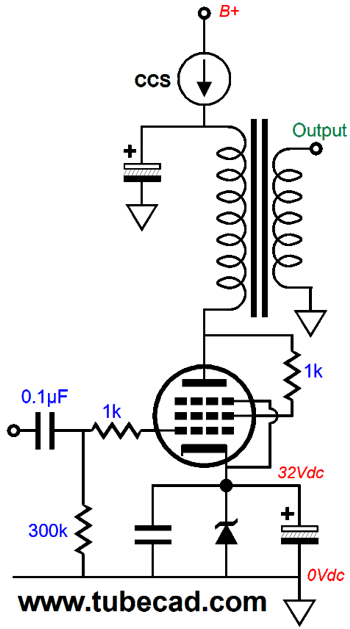
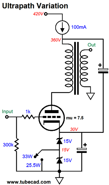
The -30V bias voltage results in the high plate dissipation, as the constant-current source must increase the plate voltage to maintain the same idle current flow in spite of the -30V grid voltage. With the -15V grid bias voltage, far less plate voltage is needed? How much less? In this example with a mu of 7.5, we multiply 7.5 by 15V and get 112.5V less. Returning to the zener version, we can introduce some ultrapath fanciness.
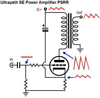
Not much of a difference, but it does imbue the output stage with the decoupling capacitor terminating into the cathode, not ground. The theory is that the audio signal will only circulate through a circle formed by the triode, the output transformer primary, and the decoupling capacitor. Does it work? In most setups, this arrangement just increases the amount of power supply that leaks out of the secondary, as the cathode sees all the power-supply noise, while the grid doesn't.
But with the constant-current source at the B+ voltage, we do not have to worry about power-supply noise. And, if nothing else, the decoupling capacitor will see slightly less voltage drop in this arrangement.
Cathode-Follower Single-Ended Output Stage
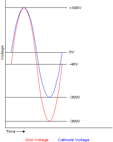
Moreover, the output tube's heater element (or filament) must get its own floating winding or heater power supply, as the output tube's cathode will undergo those huge +/-300V voltage swings, which would exceed the cathode-to-heater voltage limits; in other words, if the heater power supply were ground referenced the output tube's cathode would swing up and down 300V in relation to ground potential. In short, making a useable cathode follower output stage is not easy. Post 320, covered cathode-follower output stages and offered some workarounds. Long-time reader, Carson, sent me the following circuit, asking for my thoughts.
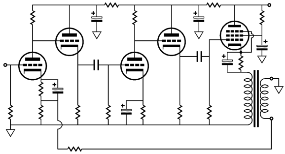
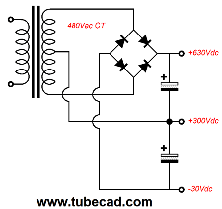
What we see is a long cascade of tube circuits: grounded-cathode amplifier, cathode follower, grounded-cathode amplifier, cathode follower, and cathode follower. Only the grounded-cathode amplifiers develop any signal gain. A negative feedback loop extends from the input triode's cathode to the output transformer's primary. Starting at the output stage, we note that the output tube only sees the peak voltage swings developed by the second grounded-cathode amplifier, which at most can only equal the B+ voltage halved. For example, if the B+ voltage were 400V, then the peak signal voltage swings would equal +/-200V. Of course, we would not actually get that great a peak swing; in fact, we would be lucky to get something like +/-150v. With such a relatively small input signal, the cathode-follower output stage will never come close to realizing its full output power output potential. The next thing I notice is the negative feedback loop, which includes all the triodes and the output transformer. This makes me nervous, as the five active stages and output transformer present many phase shifts. My view is that if you are going to employ negative feedback, then keep the loops short. Think about it: the cathode follower output stage is in itself a form of negative feedback, degenerative feedback, wherein the cathode's failing to follow the grid results in a dramatic change in current flow, thereby forcing the cathode voltage inline. What could be a shorter negative feedback than this? What I would do instead is to use two B+ voltages, the higher voltage for the input and driver stages and the lower voltage for the cathode-follower output stage. One defining feature of many tube-loving solder slinger is a hatred of bipolar power supplies or any power supply wasn't in use in 1930. Yet, getting two B+ voltages is not a big deal with a center-tapped power transformer.
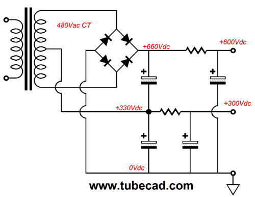
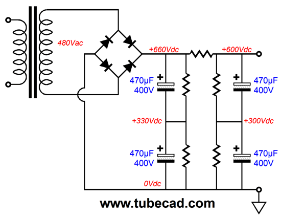
We just use four rectifiers and twice as many capacitors and RC resistors (or chokes). The alternative would be to build a 600Vdc monopolar power supply and use a humongous voltage-dropping resistor to give the cathode-follower output stage its 300Vdc B+ voltage. What a huge waste of heat and expense. In addition, since they do not make 700V electrolytic power supply capacitors, we would have to use either use big and expensive filter or oil capacitors or, what would be more common, two 400V capacitors in series with each getting its own bleeder resistor. In other words, we would end up with a power supply that would look a lot like the one shown above.
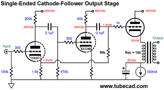
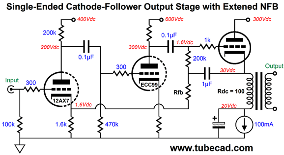
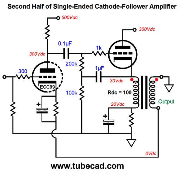
With the two B+ voltages, we can deliver the needed big signal voltage swings to the single-ended output stage.
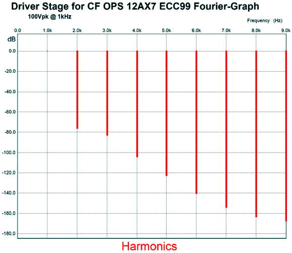
The 12AX7 delivers a gain of about 38, while the ECC99 triode delivers an additional gain of 11.7, making for a total of 407 of open-loop gain. The ECC99's cathode resistor value is 2.4k. In SPICE simulations, this frontend work well. Here is the open-loop Fourier graph for +/-100Vpk of output at 1kHz.
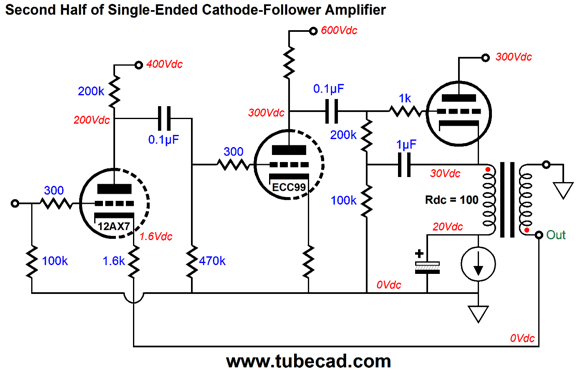
Note the negative feedback loop that ends at the ECC99's plate. In other words, the output stage runs negative feedback free. If we want to include the output triode inside the negative feedback loop, we need to add a capacitor and resistor.
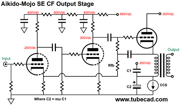
This arrangement also helps unload the ECC99, as the 200k grid resistor is effectively bootstrapped to a much higher value. The next modification that comes to my mind is adding some Aikido mojo.
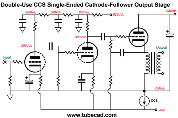
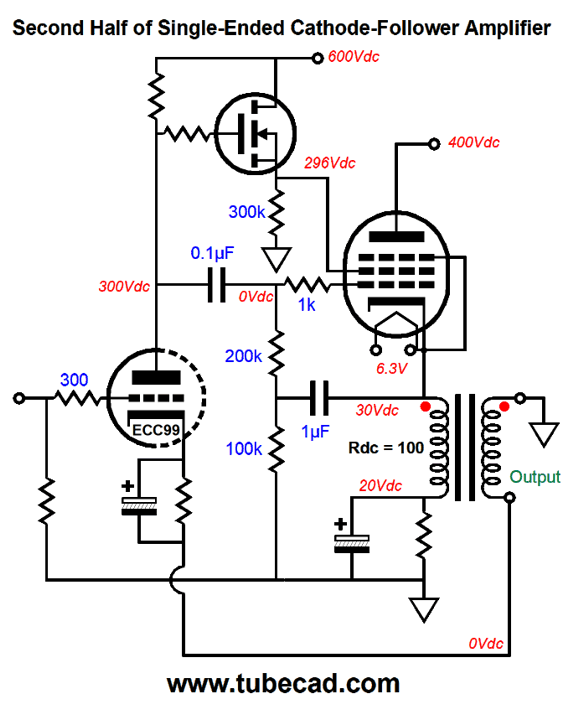
Once again, a triode's mu is the measure of the relative effectiveness of the grid over the plate in controlling the current flow through the triode; and the cathode is mu + 1 times more effective than the plate in controlling current flow. Thus, we can null the current variation that would result from power-supply noise by feeding 1/(mu + 1) of that noise to the output triode's cathode, which is what capacitor C1 does. By making C1's value equal 1/mu of C2's value, the cathode will see the needed sampling of power-supply noise. This setup assumes that the signal delivered to the output tube's grid is noise-free. Note that the output tube is auto-biased by the constant-current source. Well, we could get super clever and make better use of the constant-current source by letting it shield the entire amplifier from power-supply noise. To do so, however, requires a floating power supply.
Note the absence of RC filters, which we won't need on the output stage, as the constant-current source replaces the RC resistor. Okay, now let's design the single-ended cathode-follower power amplifier.
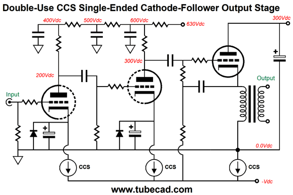
Missing from this schematic is protection diodes across the two polarized cathode bypass capacitors. Note that the constant-current source only controls the output tube's idle current, while the two grounded-cathode amplifiers use high-valued cathode resistors to set their idle current. We could replace these two cathode resistors with two constant-current sources.
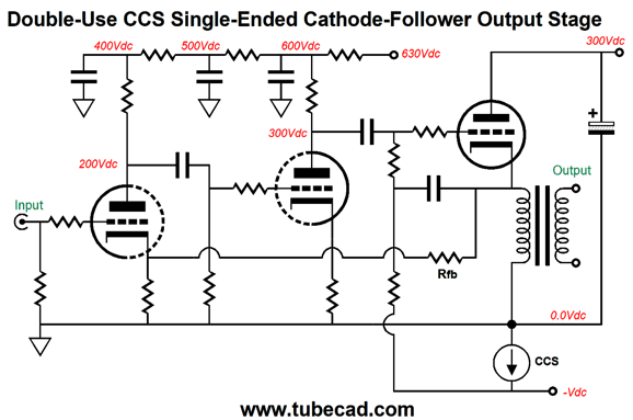
Alternatively, we could allow all of the amplifier current to flow through one constant-current source.
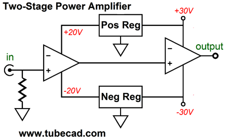
Okay, what if we employ two gain stages, each with its own negative feedback loop? Regular readers will know that I have split solid-state power amplifiers into two cascading gain stages. Why? Shorter negative feedback loops and this arrangement allows for running the input gain stage at a lower power-supply rail voltage, which can easily be regulated.
In addition, I found the clipping behavior less objectionable with the two cascading gain stages, as only the output stage ever clipped.
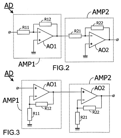
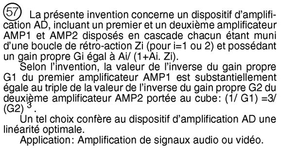
By the way, I found a French patent, FR2814008A1, by Nicolas Constantinidis and Guillaume Crinon, that claims that two cascaded amplifiers that abide to a strict gain ratio yield a net increase in linearity.
Google Patent search sadly botches the French translation into English, as it states, " (1 / G1) = 3 / (G2) 3" If look at the actual French patent, you see the ratios in gain between the first amplifier (G1) and the second amplifier (G2) should have been, (1 / G1) = 3 / (G2)³, which makes a huge difference.
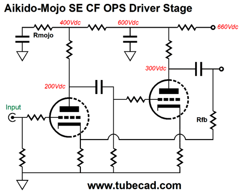
Okay, let's return to world of glass audio. We can make two cascading gain stage that each hold a negative feedback loop by adding another triode. Let's start with the first gain stage. It looks a lot like the previous setup, save for the addition of the Aikido mojo in the form of resistor Rmojo. (Search "Aikido cascade" and Aikido Cynosure" for more details.) We can use the same line up of 12AX7 and ECC99 or different tube types. The second gain stage is the more interesting one. Here we see the added triode that drives the output tube and completes its negative feedback at the output transformer's secondary. Viewed from the output, this second gain stage doesn't offer any gain, as it acts more like a unity-gain buffer. In other words, to get 8Vpk of output voltage swing, we will have to feed the input at least 8Vpk. Internal to the stage, however, huge voltage swings develop. Possibly, we might get the following to work.
What makes me nervous is phase shifts, primarily due to the inclusion of the output transformer in the negative feedback loop. Before dropping this topic, let's look at a pentode-based output stage. The N-MOSFET drives the pentode's grid-2 directly, offering a low output impedance. Since the output tube's cathode should follow the grid signal, the pentode's grid-2 will see something close to a fixed cathode-to-plate voltage, which is the definition of pentode operation.
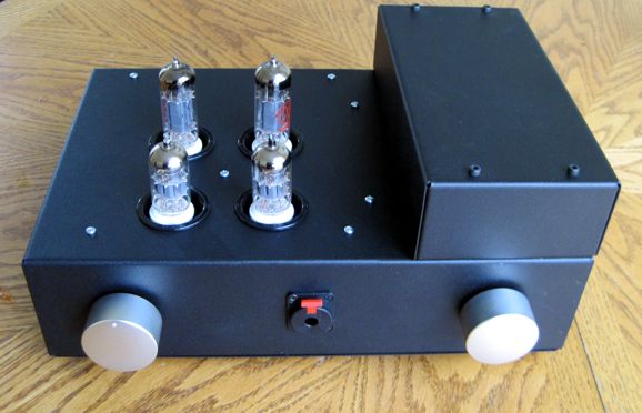
Completed Project: New Headphone Amplifier Well, that is what this new headphone amplifier does. This push-pull headphone amplifier neither uses a cathode-follower output stage nor employs a global negative feedback loop. In other words, my main motive was exploration. Wikipedia informs us that low output impedance is essential to good sound, yet most tube-based power amplifiers present relatively high output impedance, yet sound fabulous. Headphones differ from loudspeakers: headphones are intrinsically personal, not public. Thus, the standards and objectives differ between the two. Here is a rude analogy. Imagine a rich man who seeks a mistress, a stunningly beautiful woman who will dazzle and captivate the eyes of others when they go out, and who will bedazzle and enchant him when they stay indoors. Her mood, personality, and temperament are of secondary importance, as he will seldom be with her. Indeed, it might prove preferable if he and she do not speak the same language, which would sidestep senseless small-talk and the need to describe the dreary details of our day. (One old actor replied, when asked why he only sought the company of very young women, "Listening to their life stories is correspondingly brief.") Now, imagine the same rich man seeking a wife, with whom he will spend his entire day, being rich means he doesn't work. Now, her mood, personality, and temperament are of primary importance, so, too, is their ability to converse.
We should pick headphones and headphone amplifiers as if we were picking our wife, not a mistress. I know many audiophiles who sought bedazzlement, so they now own insanely expensive headphones, but seldom, if ever, listen to them. In contrast, I often spend hours listening to headphones. Thus, my test is simple: how long can I listen before I am compelled to stop? The longer, the better. Piercing highs and thudding bass initially thrill, but soon weary both ears and souls. Slight physical discomforts become prolonged agony after hours of wearing. In short, I seek comfortable and easy on my ears sound, but not a mushy or bland sound. (Back in the mid 1990s, I built a single-ended headphone amplifier that used triode connected EL84 tubes and an output transformer whose core I had hand-restacked to create an air-gap. The resulting sound was crazy lush, so much so that Frank Sinatra never sounded better. Women instantly fell in love with the sound. So what happened to it? I disassembled it and gave away the chassis. Why? Too lush, too romantic. Complex classical music came out thick, denatured, and artificially sweet.)
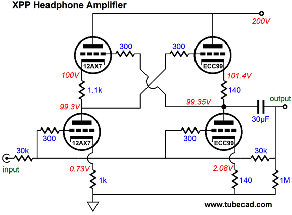
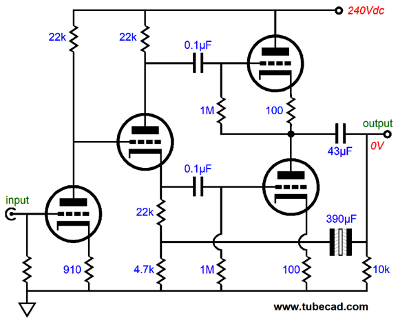
Several readers have told me that my XPP topology sounds amazing , especially as a headphone amplifier. This is not as informative as you might imagine, as audiophiles often find all sorts of things amazing, such as thin wires or thick wires, big speakers or little speakers, stiff equipment mounting or soft mounting, negative feedback and feedback-free circuits… But in the descriptions, I noted a common thread of approval: easy going, flowing, not strained. In essence, the XPP topology runs a push-pull output stage wherein the two output triodes function as grounded-cathode amplifiers, not cathode followers. In other words, it delivers a moderate output impedance, (rp/2) not a low or supremely high output impedance. No doubt, many are thinking that anything other than an extremely low output impedance is a bad idea. But are you aware that there exists an audio-electronics standard that dictates an output impedance of 120-ohms for headphones, the 1996 IEC 61938 headphone standard? In addition, did you know that most commercial headphone amplifiers hold either a 10- or 20-ohm resistor in series with their outputs, which protect the amplifiers from shorted headphone cables? Okay, I admit that some headphones require a low output impedance, as there bass performance will otherwise bloat. At the same time, I am sure that other headphones sound far better with a higher output impedance. One size does not fit all. The new headphone amplifier's circuit is not an XPP, but basically a small OTL amplifier without a negative feedback loop. Here is an abbreviated schematic, which leaves out grid-stopper resistors and an internal coupling capacitor.
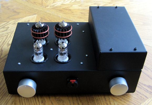
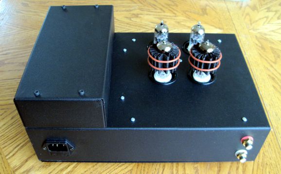
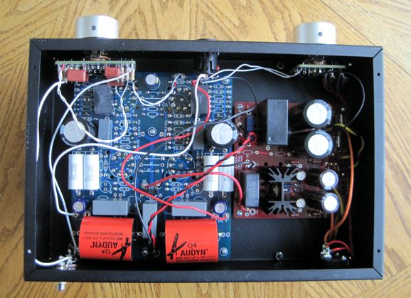
The grounded-cathode amplifier input stage delivers the needed signal gain, which the following split-load phase splitter then relays to the two output triodes. The coupling capacitor connects to the headphones. The 390µF capacitor that bridges the output to the phase splitter ensures equal amplitude drive signals to the two output triodes. Without this capacitor, the bottom triode would be grossly overdriven, as its cathode barely moves, while the top triode's cathode swings with the output voltage swings. Okay, now down to the details of construction. I used two 50VA toroid power transformers, one 12Vac and one 240Vac. Both are larger in VA rating than needed, but I like overdoing power transformers, as it sidesteps heating and hum issues. I situated them inside the small enclosure that attaches to the top of the chassis. The chassis is a painted steel box made by Hammond and is 3in tall by 12in wide and 8in deep. The smaller box, also made by Hammond, is 2in tall by 4in wide and 8in deep.
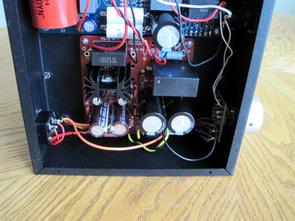
The power supply is a PS-3 that sports two 390µF/400V snap-in electrolytic capacitors in an RC filter arrangement. The headphone amplifier PCB holds two RC filter, one per channel, also made up of 390µF capacitors. The raw power-supply voltage comes in at about 335Vdc, which reduces to 240Vdc after the two RC filters.
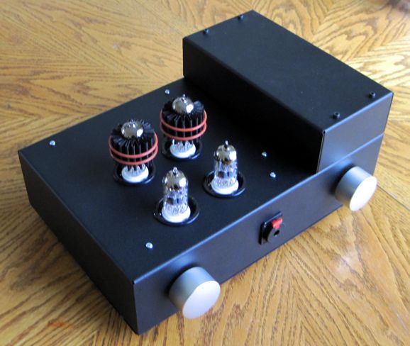
The output tube is an ECC99 made by JJ, which runs a hot 22mA idle current. Because of the high dissipation (over 5W per ECC99), I use Pearl cooler heatsinks, which not only cool the tubes well, but seem to provide some anti-microphonic benefit. I have actually measured the glass envelope temperatures with and without the coolers; they work. Right now, I am about to experiment by grounding the cooler with a high-temp wire.
Of course, some prefer the appearance of naked tubes and are willing to live with shorter tube life-spans to see the soft red glow. In a dimly lit room, the glow is lovely.
The RCA jacks are NOS Cardas type. I don't know if they are still being made, but I certainly hope so.
The headphone jack is made by Neutrik in Liechtenstein; it is a locking design, which I don't like, as I would prefer to let the headphone plug just slide out of the jack during an accident rather than have the entire headphone amplifier follow me about the room.
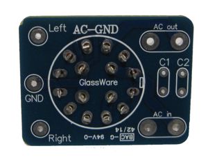
The power switch is different, as it is not one of my Select-AC switches that allows staggered turn on of two power transformers; instead, this switch holds three positions: off and hard mute, on and hard mute, and on and no mute. A hard mute is when the two outputs are directly shorted to ground. The advantage here is that turn-on and turn-off thumps are eliminated. In addition, having a mute position is great when the phone rings or someone calls out my name. No, the AC-GND switch is not yet available at the GlassWare-Yahoo store. Alas, the switch needed will not be available for the next few months.
In addition, this headphone amplifier does not hold a volume control (the knob on the left is one of my five-position Tilt Control designs). What? No volume pot? All the signal sources I use already hold a built-in volume control. Speaking of the Tilt Control, I find this the essential feature for any headphone amplifier. In fact, it probably makes a bigger difference than tube rolling. Moreover, I find that it redeems headphones. What does that mean? I tend to view my Grados as rock headphones, my Audioquest headphones as jazz headphones, and my Sennheiser headphones as classical headphones. But with a twist of the Tilt Control, each can ably jump into other music genres.
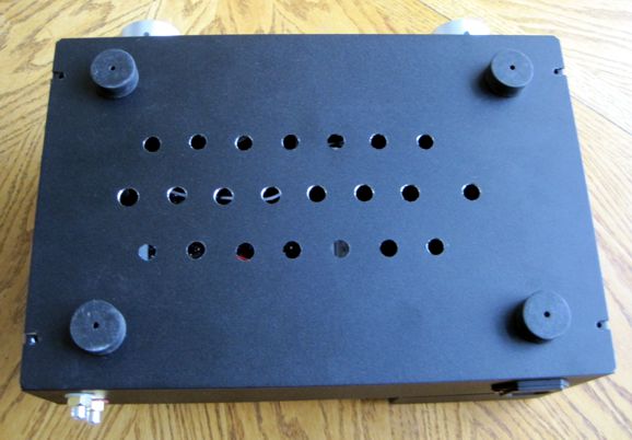
The amazing thing is that everything fit. Once again, I used too small a chassis. Just because I can fit all of it into a tight space does not mean that I should. If the bottom enclosure were just two inches wider, life would be much easier. Actually, it being just one inch deeper would have made a huge difference. If I had to make it all over again, I would lower the two knobs and the headphone jack by half an inch, which would let me drop the amplifier PCB by half an inch, as I prefer not to see the white ceramic tube sockets. Still, I am pleased with the look of the headphone amplifier.
I drilled 23 holes on the bottom panel and added four solid rubber feet. How does it sound? No question could be more disagreeable to me, alas. In general, seldom does it prove profitable to ask a mother how lovely her children are. Beyond the issue of subjectivity, a subjective opinion not in the least disinterested by the way even though I am not selling the amplifier or its main PCB, there is the problem of tube rolling. For example, in the input position, I am running NOS Telefunken ECC82, smooth plates, diamond bottomed, which few readers have ever seen and fewer still own. (Last time I looked, they sold for over $100 each.) Moreover, my headphones are the means by which I judge the headphone amplifier's sound, as my ears must always find an intermediate mechanical-electrical device. Okay, having said all this, I find the sound quite tube-like. Not tubby, but sounding like tube amplification, smooth, stress-free, and, at times, shockingly intimate. I hear far more sustain to plucked and hammered notes; and the room ambiance clearly accompanies the music. The music pours out instead of being spit out. Last night, I listened to Tidal through a USB DAC and the new headphone amplifier. My ears were happy in the extreme. My reference tube headphone amplifier (an Aikido push-pull amplifier) is out on loan to a friend. When the pandemic passes, I will conduct a proper shootout. My friend owns Sennheiser HD800 headphones, which should make the shootout even more interesting. (By the way, with a little effort, I can add a negative feedback loop and dramatically reduce the output impedance.) Although the 43µF output coupling capacitors are only large enough in value to allow the 300-ohm HD650 headphones to go down to 12Hz, they limit 32-ohm headphones to extend down to only 116Hz. Nonetheless, I gave my Grado headphones a listen on the new headphone amplifier. I was surprised that it worked as well as it did. In fact, the idea that came to mind was to revive my old practice of listening to headphones with a subwoofer. Here I quote myself from post 367, wherein I wrote about the SRPP headphone amplifier that I built over 40 years ago for driving my Sennheiser HD-414 headphones:
If your family and neighbors will allow you to, you should try this arrangement. Just impose a first-order high-pass filter at 100hz to 200Hz for the headphones and let the subwoofer fill in the missing bass with a third-order low-pass filter. The subwoofer provides the otherwise missing sonic smack and sock in the guts, while the headphones deliver the seamless midrange free of crossovers. Of course, we do lose the headphone's main advantage of not annoying others.
Music Recommendation: Kondonassis, Vieaux; Together Do you remember how you felt the first time you heard the Kronos Quartet? I do. I remember thinking that it was an amazing feat to actually make a hip classical album, an album that actually succeeded at being hip and yet musically sound. (I remember only being irked by Nigel Kennedy's punk hair-dos.) Returning to the album, the two play fresh compositions (the oldest composer in the collection being the late Alan Hovhaness) and deliver a fresh blending of instruments seldom if ever brought together. For audiophiles, you should definitely give the third track a listen. The best capsule review I found was at arkivmusic.com.
I plan on reading all of Mr. Veterano's reviews. At Tidal we find Together and three other albums by Kondonassis.
In contrast, Amazon Music beats Tidal by one album.
I dipped my ears into her album, American Rapture, and I liked what I heard. It is next on my list of albums to hear. //JRB
User Guides for GlassWare Software
For those of you who still have old computers running Windows XP (32-bit) or any other Windows 32-bit OS, I have setup the download availability of my old old standards: Tube CAD, SE Amp CAD, and Audio Gadgets. The downloads are at the GlassWare-Yahoo store and the price is only $9.95 for each program. http://glass-ware.stores.yahoo.net/adsoffromgla.html So many have asked that I had to do it. WARNING: THESE THREE PROGRAMS WILL NOT RUN UNDER VISTA 64-Bit or WINDOWS 7 & 8 or any other 64-bit OS. I do plan on remaking all of these programs into 64-bit versions, but it will be a huge ordeal, as programming requires vast chunks of noise-free time, something very rare with children running about. Ideally, I would love to come out with versions that run on iPads and Android-OS tablets.
//JRB
|
|
I know that some readers wish to avoid Patreon, so here is a PayPal button instead. Thanks. John Broskie Special Thanks to King Heiple
John Gives
Special Thanks to the Special 83
I am truly stunned and appreciative of their support. In addition I want to thank the following patrons:
All of your support makes a big difference. I would love to arrive at the point where creating my posts was my top priority of the day, not something that I have to steal time from other obligations to do. The more support I get, the higher up these posts move up in deserving attention. If you have been reading my posts, you know that my lifetime goal is reaching post number one thousand. I have 497 more to go. My second goal was to gather 1,000 patrons. Well, that no longer seems possible to me, so I will shoot for a mighty 100 instead. Thus, I have 17 patrons to go. Help me get there.
Only $12.95 TCJ My-Stock DB
Version 2 Improvements *User definable Download for www.glass-ware.com |
||


| www.tubecad.com Copyright © 1999-2020 GlassWare All Rights Reserved |