| John Broskie's Guide to Tube Circuit Analysis & Design |
01 May 2020 Post Number 502
40dB Hybrid Phono Preamp
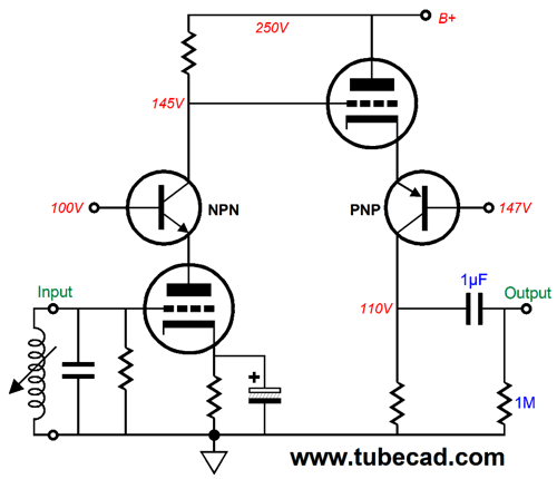
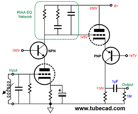
In both cascodes, the gain is roughly equal to the triode's transconductance against the collector resistor, as the triode transconductance is preserved. In a grounded-cathode amplifier, the triode's transconductance falls due to the plate resistor and to an unbypassed cathode resistor. In contrast, the cascode locks the triode in place so that much more of its transconductance survives. All we have above is a very high gain preamplifier. To create a phono preamp requires adding an RIAA equalization network, but the not the typical arrangement. Why not? The cascode's output impedance is insanely high, roughly equal to the collector resistor value. In other words, the cascode functions as a voltage-to-current converter, turning the input voltage signal into output current signal. Thus, we should use an RIAA equalization network that converts the current signal back into a voltage signal.
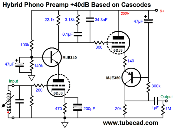
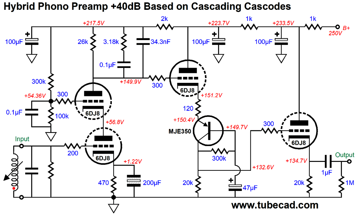
We do not lose any DC voltage or low-frequency gain in this arrangement, but the frequencies from 50Hz to 500Hz are reduced by 20dB and those frequencies above 2122Hz see a first-order low-pass filter. Here are the actual part values.
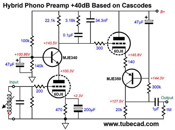
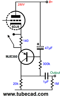
The input cascode's cathode resistor is bypass by a non-polarized electrolytic capacitor. The retrograde cascode's triode gets a 140-ohm cathode/emitter resistor to burn off some of its transconductance, which lowers the gain down to 40Db for the entire phono stage. The RIAA equalization network imposes the inverse of what was imposed on the signal prior to pressing the LP. Okay, let's add the DC voltages.
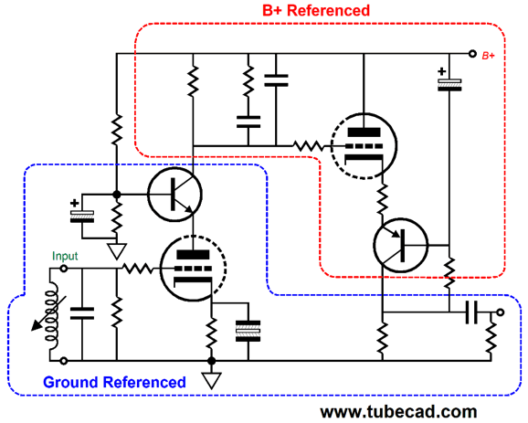
As you can see, both triodes experience about 100V of voltage drop and both draw around 5mA of current each. The DC gain is 1,000 (+60dB) and the gain after equalization is 40dB. Note that the input cascode sees the triode's grid being voltage referenced at 101V and the shunting capacitor terminates into ground. In contrast, the second cascode, the retrograde, sees 144.3Vdc reference voltage for the PNP transistor's base and the shunting capacitor terminates into the B+ voltage. This is important. We want the second triode to see the same amount of power-supply noise at its cathode as its grid sees, which is close to 100%, as the input cascode presents a dismal PSRR. Here is the meta way to see the entire circuit.
The input triode and the output are all ground referenced. On the other hand, the RIAA equalization and the second triode are B+ voltage referenced. Had the base capacitor terminated into ground, as most tube gurus would have instinctively done, the PSRR would have gone positive; in other words, we would see the power-supply noise amplified, not attenuated. Even with this more coherent bypassing, the phono stage requires a well-regulated power supply or an extremely well-filtered power supply. Let's return to the second stage and its cathode resistor. If more gain is desired, we can remove the resistor, which will increase the gain to 47dB. I would add a switch, so I could enjoy the option of two gain settings.
Of course, we would only flip the switch when the preamp was powered down. Note that only one tube and one coupling capacitor was used. If you wish, you can use two tubes instead.
Here we see a far more conventional input stage, as the two-triode cascode is commonly used. The second stage gains a cathode follower output stage, which offers a far lower output impedance (about 100 ohms) and isolates the retrograde cascode's collector resistor from external loads. The RIAA equalization network now holds a 26k plate resistor, as the top triode's output impedance is quite high, but not high enough not to drag down the network. Increasing the plate resistor value undoes the plate resistance. Note that all of the preamp is now ground referenced, as all the RC filters on the B+ voltage and the voltage reference shunting capacitors all terminate into ground. This is how your grandfather did it, save for the use of the sole PNP transistor. Because of the three cascading RC filters, the PSRR is quite good.
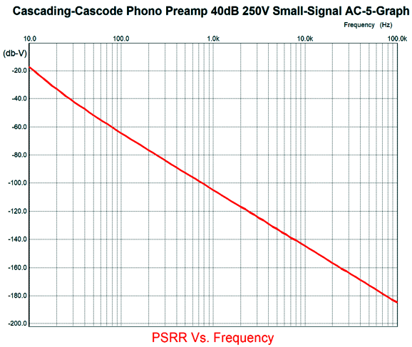
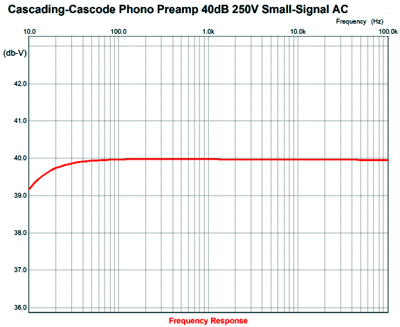
The critical frequencies center between 100Hz and 120Hz, as that is where the ripple frequency will be found. Here is the SPICE-generated frequency plot.
Not bad at all. By the way, the cathode resistor bypass capacitor of 200µF was as high as I could go, without incurring a bass-hump as a subsonic frequency, something we must avoid with warped LPs. Further hotrodding is possible—such as adding two constant-current sources to increase both the current flow through the triodes and the gain, while lowering the noise—but I would love to hear this preamp as it stands.
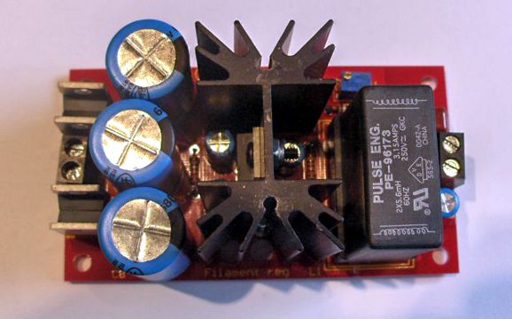
More DHT Heating Constructors who have the kits get comprehensive manuals: Rod didn't provide a schematic, nor will he, as his design is proprietary, which I must respect. Of course, that won't do much for those of us who seek to know the how of a circuit not the what of it. It turns out that a DHT filament power supply is being made and sold that makes use of a common-mode choke, which I think is a great idea.
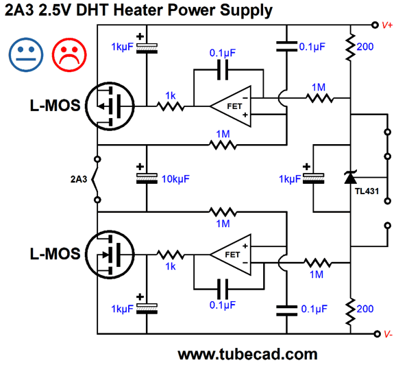
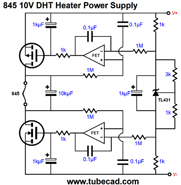
It is made and sold by the famous and fellow Coloradian, Pete Millett. I have been giving the problem of how to best heat DHT filaments more thought and I have revised one of my solutions.
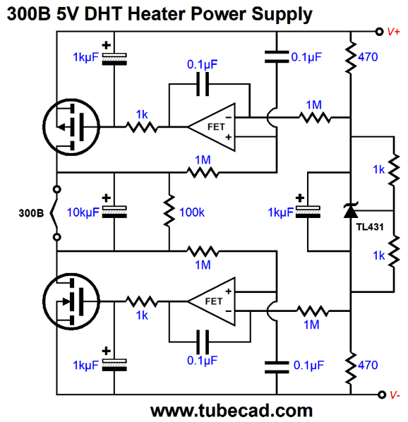
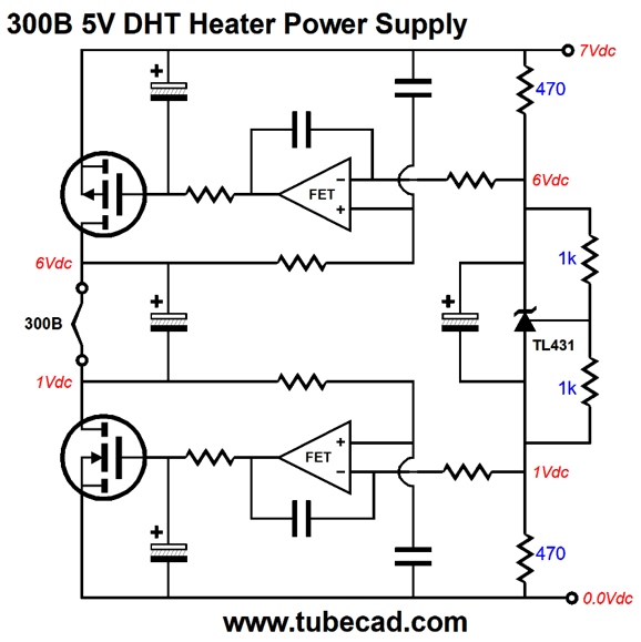
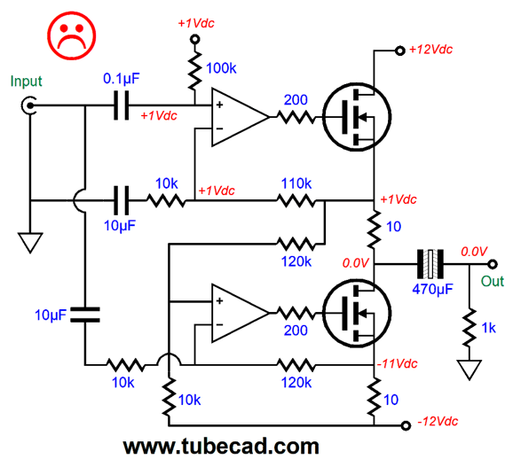
The 10kµF capacitor and the 100k resistor are optional. I am inclined to think that the capacitor is a very good idea, but I have never held a sonic shootout. The 100k resistor would just give the two MOSFETs something to bite on when the triode was missing from its socket. I had three goals: efficiency, high impedance, and a fixed DC voltage across the filament. A DHT regulator that puts out 5V should not require a 15V raw power supply voltage. Ideally, with 5V of output, a 7V to 8V floating power supply should suffice. If high-impedance is all that its boosters claim it is, then let's have truly high impedance. High impedance means regulated current flow, not regulated voltage. Or does it? Cannot we have both? My design establishes a fixed DC voltage across the filament, while providing top and bottom high-impedances. In my previous design, I used one OpAmp to set the voltage drop across the filament and one to center the filament inside the voltage window provided by the raw power supply. The more I thought about, I realized that I could use both OpAmps to establish the fixed DC-voltage-drop and also auto-center the filament within the raw power-supply voltage. In other words, given a 7V power supply, the 5V drop across the filament would leave one volt below and one volt above the filament.
The TL431 is an adjustable voltage reference that works between 1mA to 100mA of current flow and can deliver a reference voltage from 2.5V to 36V. (One secret, few know, is that the TL431 can be configured as an amplifier.)
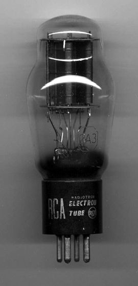
What about heating 2A3 triodes? The 2A3 puts out far less power than a 300B, but in terms of heating their filaments, it's closer to being a draw. The 300B requires 5V at 1.2A, whereas a 2A3 requires 2.5V at 2.5A. Okay, let's do the math: 5V against 1.2A equals 6W; 2.5V against 2.5A equals 6.25W. The problem with heating a 2A3 with DC is that the rectifier losses become a much larger issue. Moreover, even if we use a low-drop-out (LDO) voltage regulator, the voltage regulator will need at least a 1.5V voltage headroom to maintain regulation in the face of droops in the wall voltage. Well, the 2A3's twice as big filament current draw means twice the heat from the voltage regulator, which is why in general, I have recommend just using a 2.5Vac transformer winding to heat the 2A3's filament. Would my circuit work with the 2A3? It certainly could, if the floating power-supply voltage were high enough, which is a pain and watses heat. The big problem is that the standard MOSFETs require much larger turn on voltages than transistors do. The exception is the lateral type of MOSFET, but these are both rare and expensive; however, in a world of $200 coupling capacitors and $10 resistors, the extra cost is not that out of line.
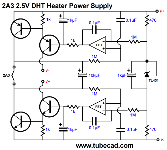
No, the bigger problem is that lateral types exhibit far less transconductance and, thus, far higher effective series resistance, which against 2.5A of current flow means that they won't cut it, unless a several were placed in parallel. Alas, the best solution is to use bipolar transistors. Since 2.5A is serious current flow, we should use serious power transistors, such as the MJL1302A and MJL3281A, which are 15A, 260V, 200W devices. The following variation works with a floating power-supply voltage of only 4Vdc.
The bases of the Darlington transistors require only about 1.5V to summon 2.5A of current flow from the output transistors, which fit inside the 4V voltage window and the output voltage swings of the AD823 dual OpAmp. The TL431 has been configured as a 2.5V voltage reference and output centers nicely. With a raw 4Vdc voltage power supply, the output transistors will only dissipate about 2W. With a power-supply voltage of 10.5Vdc, they would each dissipate 10W, which is toasty. I would try to stick around 5Vdc.
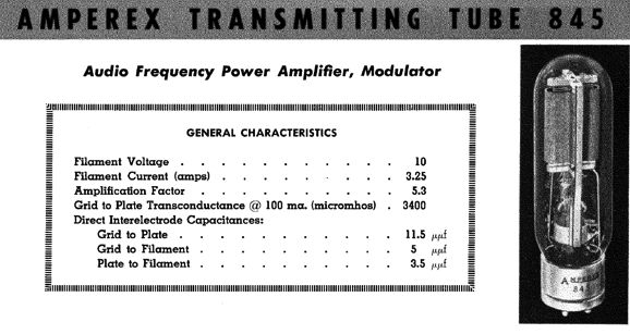
What about at the other extreme, say an 845 output tube? The 845 triode's filament needs to see 10V at 3.25A, which implies 32.5W of dissipation from the filament. I would use the MOSFET-based version, as it offers better performance and MOSFETs tend to be closer to bullet-proof than transistors.
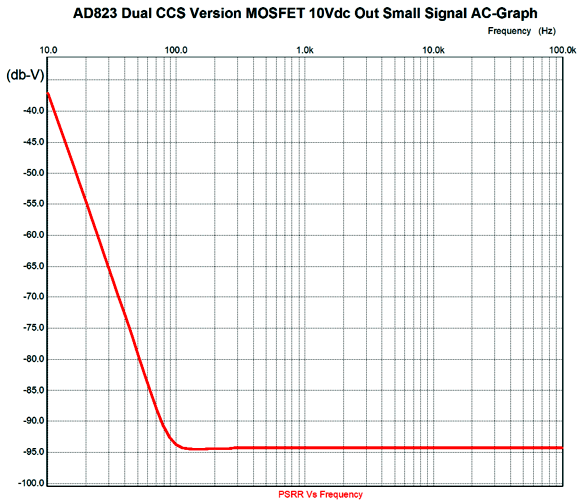
The same TL431 provides the 10V voltage reference and the same AD823 OpAmp controls the MOSFET's current flow. In SPICE simulations, this circuit worked well with a power-supply voltage of only 13Vdc. I would not go over 16Vdc. Here is the PSRR-versus-frequency graph.
If we want to push the null further down in frequency, we can increase all the 0.1µF capacitors to some equal but larger value, say 0.68µF.
Error Reduction Circuit
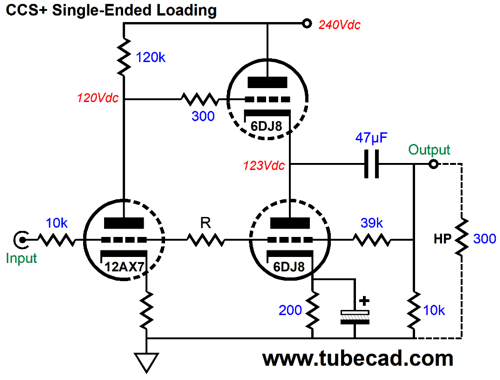
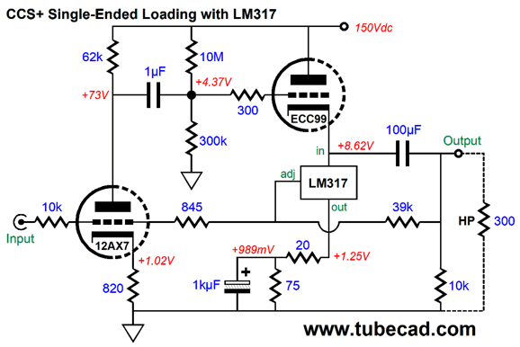
The external load impedance is a low 300 ohms, the impedance of the Sennheiser HD580 headphones I owned at the time. With such a low impedance, we can expect fairly high distortion. The 12AX7 is configured as a grounded-cathode amplifier, while the top 6DJ8 functions as a cathode follower. The bottom 6DJ8 triode acts as a constant-current-source—plus. The plus being the error reduction. Ideally, we find the right value for resistor R, which will give the best input signal null at the bottom 6DJ8's grid, as we want to retain the single-ended operation and not introduce push-pull functioning through a backdoor. (Such a cheat goes by the name of "Guided CCS.") If we were dealing with OpAmps, this wouldn't be a concern, as their open-loop gain is so high that close to no positive signal appears at its inverting input.In contrast, the input triode must see some tiny amount of input signal to develop enough signal to satisfy the gain ratio imposed by the inverting negative feedback loop. But somewhere to the right of the resistor there must be a input signal null, as the output signal is inverted relative to the input signal. Now, here is the interesting part: at this point of deepest null, a signal will survive, i.e. the distortion signal, as this signal does not find an inverted version of itself in the input signal. In other words, the bottom triode's grid would only see the distortion signal, so its current conduction varies in response to the distortion. Read post 20 to see how well this idea worked. Early on, I realized that the bottom 6DJ8 could never work as well as I had hoped, as it only saw an attenuated amount of the output distortion, and it lacked sufficient transconductance to force a complete distortion null. My last thought on this topology is the following.
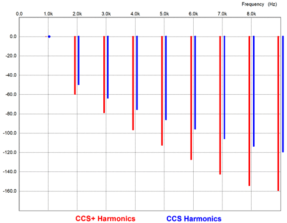
The LM317 replaces the 6DJ8. In fact, the top 6DJ8 is replaced by an ECC99 triode. All three negative feedback resistors form an attenuator on the output distortion that the LM317 sees at its adjustment pin, about 20% is left, so we must reduce the LM317's load resistor value to force an amplification effect on its current conduction. In other words, if the ECC99's output impedance at its cathode is 100 ohms, we must use 20% of this value for a load resistor. Of course, we cannot actually use such a low value, as the resulting idle current flow would equal 1.25V/20 or 62.5mA. Thus, we place a bypassed 75-ohm resistor in series with the 20-ohm resistor, bringing the idle current down to a reasonable 13.2mA. Here is the SPICE-generated results from a shootout between plain constant-current source and the more active CCS+.
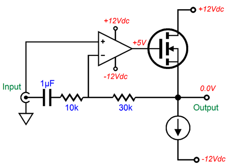
Note that the 9th harmonic improves by -40dB, which is huge. Okay, how do these circuits relate to the DHT heater power supply design? As I looked at the schematic, I was reminded of a solid-state, single-ended power amplifier design I had sketched that held two MOSFETs driven by two OpAmps. The top MOSFET delivered the output signal, while the bottom functioned as the constant-current source. This type of single-ended amplifier can only yield a theoretical maximum efficiency of 25%, with reality coming in closer to just 20%. Here is the obvious way to do it.
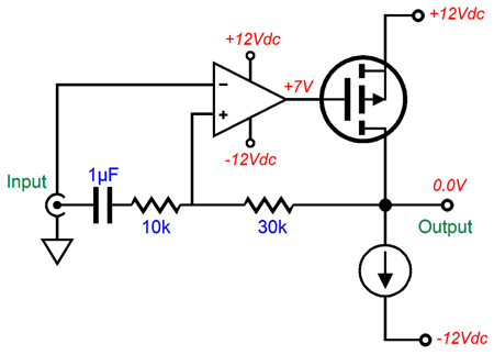
The top MOSFET is configured as a source follower. The amplifier inverts the input signal and uses one fewer coupling capacitors as a result. Here is the non-inverting setup.
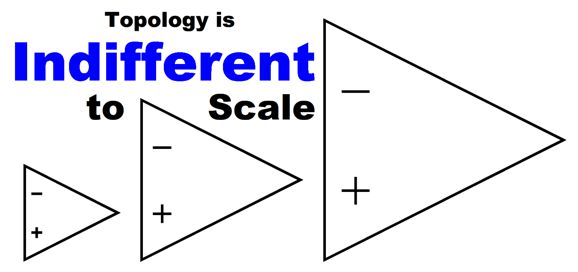
What makes it different is that the top OpAmp's inputs have been swapped, as the top MOSFET inverts the signal at its gate, the result of being configured as a common-source amplifier. In other words, the MOSFET and amplifier must be seen as combining into a single amplifier. This topology allows us to get far more voltage swing than would otherwise be possible, as the source-follower configuration would require the top OpAmp to deliver output voltage swings in excess of the positive rail voltage. In contrast, the P-channel MOSFET configured as a common-source amplifier must be turned on by a voltage less positive than the positive rail voltage. So far, we just have a single-ended power amplifier loaded by a constant-current source. In fact, the original idea was power amplifier just powerful enough to drive low-impedance headphones, not loudspeakers. Of course, topology is independent of scale.
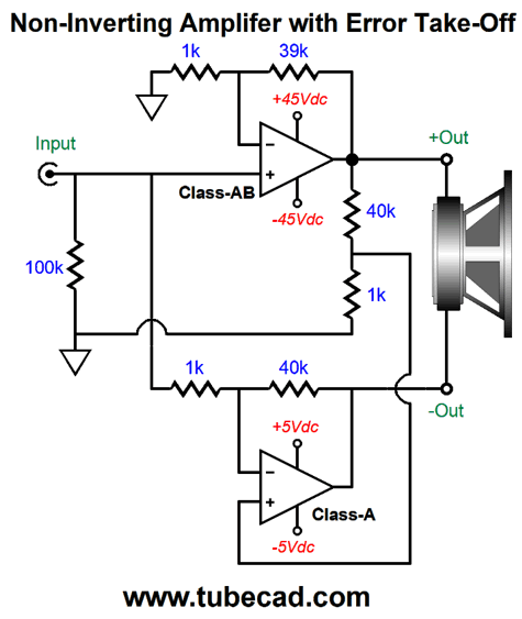
To transform the amplifier into a loudspeaker amplifier only requires upping the idle current. By how much? Well, with -/+12Vdc power-supply rail voltages, we need only divide 12V by 8 ohms to get 1.5A of idle current, which due to the constant-current source loading also equals the peak output current swing. Let's assume that we can actually realize 10Vpk output voltage swings. To translate this into watts we square the voltage and divide the result by twice the loudspeaker impedance; in this example, we get 10²/16 or 6.25W. Not much, but probably more than enough for horn loudspeakers or computer speakers. By the way, 1.5A of idle current against the power-supply differential voltage of 24V equals 36W of heat dissipation at idle, which implies an efficiency of only 17.4%, not the 25% promised in textbooks. Okay, the question remains: how do we use the constant-current source to perform some error correction, reducing the output distortion? Here is the idea that immediately came to mind.
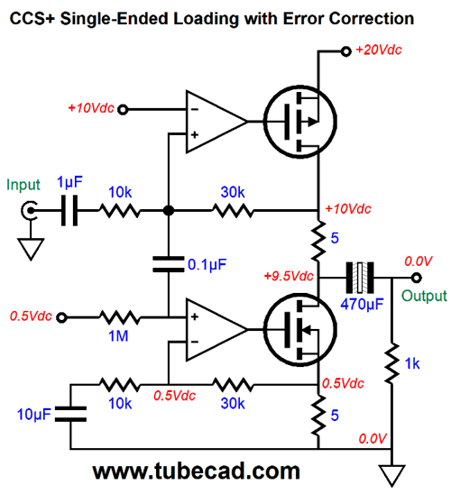
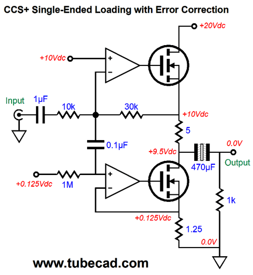
The bottom OpAmp sees two signals at it non-inverting input: a DC reference voltage and the AC distortion created by the top amplifier. Since the distortion was attenuated by the 10k and 30k negative feedback resistors, which defined a two-resistor voltage divider that reduced the distortion signal by 75%, the bottom OpAmp must amplify the AC distortion signal by fourfold. This task is performed by the bottom 10k and 30k negative feedback resistors. Superimposing the distortion on the bottom 5-ohm source resistor creates an anti-phase current flow through the N-channel MOSFET and the top 5-ohm drain resistor. The result is a null in the distortion at the output. Well, that is the theory. In SPICE simulations, I only got good results when I forced the top OpAmp and MOSFET into gross distortion. The distortion went from 3% to 0.1%, which is not as much as I expected. The problem as I see it is that phase shifts undo much of the potential error correction. One workaround might be to forgo the amplifying of the distortion signal by the bottom OpAmp. In other words, we might simply attach the bottom OpAmp's inverting input to the bottom MOSFET's source resistor, a resistor we make 1/4th as large in value as the 5-ohm above it. Effectively, we are getting current gain without having to use voltage gain. What makes this problematic is that the voltage drop across the bottom resistor would have to be quartered. In this example, the 0.5V drop must be reduced to 0.125V. That is not much voltage, so the OpAmp must be carefully chosen to work with an input signal that comes that close to its negative power-supply rail voltage.
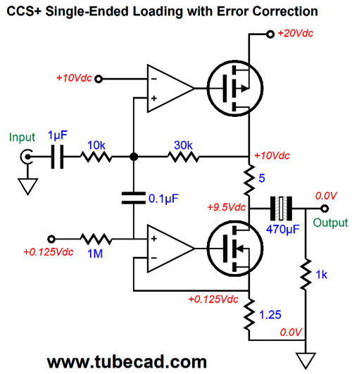
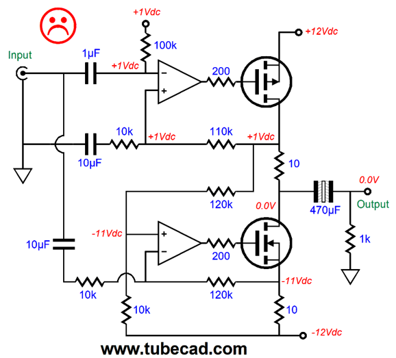
Now, let's see the version that replaces the top N-channel MOSFET for a P- type.
Note that monopolar power supplies have exclusively been used. Why? If you use a bipolar power supply in SPICE, you will encounter no problems. But in reality, the ripple on the negative power-supply rail will become a signal to amplify, as the bottom OpAmp's non-inverting input is blind to it. I tried to come up with bipolar designs, but with little success.
And:
The problem of the negative power-supply rail noise persists. The only time these setups would work is when the gain was to 2 (+6dB). By the way, this last design was inspired by my extension of the Sandman class-S topology to non-inverting power amplifiers.
See post 467 for more details. In other words, this is a work in progress. We start with a powerful headphone amplifier and then we can scale up to a loudspeaker power amplifier. One idea I have been toying with is to use a MOSFET-based constant-current source and then add a smaller OpAmp-driven constant-current source that would idle at a fraction what the large constant-current source would draw, say one tenth, but would be responsible for the error correction. Of course, many would argue that single-ended operation is already more than good enough, so why gild the lilly? Shakespeare, King John:
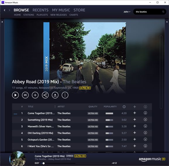
Music Recommendation: Amazon Music
Not bad, especially considering that three other family members were video conferencing while I ran the test. Actually, my main computer is so old that its network-cable receiver chip limits the maximum download speed to slower, far slower, than my Sony smart phone or laptop, both of which use WiFi not CAT-6 cable. Nonetheless, I have encountered no hiccups from playing 196kHz music from Amazon Music.
So far, what I like is that I am not instantly turned off by the juvenile screen litter that Tidal like to hurl into my eyes. Instead, when the Amazon Music app starts up it simply returns to the last album I played. (This alone makes me much happier, as I could easily and happily go the rest of my life without seeing Tidal's top ten list again.) I remember traveling to distant record shops, decades ago, my wallet itching to spend on LPs. I remember bringing wish lists and eagerly digging into the bins, my stack of LPs growing ever taller. But as I suffered the sonic onslaught, the crunching, banging, slamming that was the dreaded employees-selected music, i.e. the ceaseless jack-hammering of grunge music, music that the Geneva Convention prohibits from playing before war criminals, my vinyl-purchasing enthusiasm waned. As my ears ached and my spirit withered, I began removing albums from my stack. Eventually, the auditory ambush won; pustular, aggrieved, and sullen, the 20 year-old employee took my money; and I left with only a few of the LPs that I would otherwise have purchased. I mentioned this once to an owner of a record store. He saw my point, but claimed that if he restricted their playlists, he would have to pay them more; if he forced them to play classical music, they would quit. So sad. What is the secret of Starbucks, other than having Pete's Coffee as a precursor and model? They never let their employees play their music. Instead, only music selections from those CDs that Starbucks sells can be played. Thank God. Imagine the alternative, then shudder. Instead of MQA, Amazon Music offers high resolution music files, all the way up to 24-bit at 192kHz. Alas, much like Tidal, Amazon does not get classical music; not at all. The categories of composer, conductor, orchestra, and featured soloist do not exist; or, rather, they exist as "singers," much in the same way that all tracks are labeled as songs. Sometimes I find a desired album by searching for the composition's title or the conductor or the orchestra. Why? Dear God, why? Tidal used to be owned by a famous rapper, what is Amazon's excuse? Given ten minutes, I could come up with ten different ways that we could search classical or jazz or hip-hop music. For example, there are times that I would like to browse just one recording label, such as Angel or BIS. There are labels I trust. If ECM believed an album was worthy of producing, I am willing to hear it. No doubt, you have seen those large posters that map out all the major languages spoken today and show the paths through time where they commingled and spurred off. In veterinary offices, I have encountered huge posters of all the branches of dog breeds. I would love to see such a mapping of music. (I assume 2D maps, but why not 3D maps?) For example, we could survey the hundreds of outgrowths of popular music and trace their heritage. We could scrutinize the rivulets and rivers of influence on a classical conductor. For example, if you love Carlos Kleiber—the half-Austrian and half-American conductor who grew up in Argentina and had an English governess and attended English boarding schools and studied chemistry in Zurich—you could find which conductors had influenced him (his dad for one) and those he had influenced, then select them for listening. Put differently, we are poorly served by the tech giants, as seeking out soul-lifting music is altogether different from shopping for shoe inserts. Too soon to tell if I will abandon Tidal. I am inclined to believe that I will end up subscribing to both, much in the same way as I belong to both Costco and Sam's Club, as individually neither sells al that I want to buy.
//JRB
User Guides for GlassWare Software
For those of you who still have old computers running Windows XP (32-bit) or any other Windows 32-bit OS, I have setup the download availability of my old old standards: Tube CAD, SE Amp CAD, and Audio Gadgets. The downloads are at the GlassWare-Yahoo store and the price is only $9.95 for each program. http://glass-ware.stores.yahoo.net/adsoffromgla.html So many have asked that I had to do it. WARNING: THESE THREE PROGRAMS WILL NOT RUN UNDER VISTA 64-Bit or WINDOWS 7 & 8 or any other 64-bit OS. I do plan on remaking all of these programs into 64-bit versions, but it will be a huge ordeal, as programming requires vast chunks of noise-free time, something very rare with children running about. Ideally, I would love to come out with versions that run on iPads and Android-OS tablets.
|
I know that some readers wish to avoid Patreon, so here is a PayPal button instead. Thanks. John Broskie
John Gives
Special Thanks to the Special 81
I am truly stunned and appreciative of their support. In addition I want to thank the following patrons:
All of your support makes a big difference. I would love to arrive at the point where creating my posts was my top priority of the day, not something that I have to steal time from other obligations to do. The more support I get, the higher up these posts move up in deserving attention.
If you have been reading my posts, you know that my lifetime goal is reaching post number one thousand. I have 498 more to go. My second goal was to gather 1,000 patrons. Well, that no longer seems possible to me, so I will shoot for a mighty 100 instead. Thus, I have 19 patrons to go. Help me get there.
Support the Tube CAD Journal & get an extremely powerful push-pull tube-amplifier simulator for TCJ Push-Pull Calculator
TCJ PPC Version 2 Improvements Rebuilt simulation engine *User definable
Download or CD ROM For more information, please visit our Web site : To purchase, please visit our Yahoo Store: |
|||


| www.tubecad.com Copyright © 1999-2020 GlassWare All Rights Reserved |